
Installation Guide
Page 1
which is located on the rear panel of the cabinet. Model No. Retain this information for future reference. Serial No. PLASMA DISPLAY MONITOR GD-V501U INSTRUCTIONS For customer Use: Enter below the Model No. and the Serial No.
which is located on the rear panel of the cabinet. Model No. Retain this information for future reference. Serial No. PLASMA DISPLAY MONITOR GD-V501U INSTRUCTIONS For customer Use: Enter below the Model No. and the Serial No.

Installation Guide
Page 4
... TIMER Set 31 Speakers connection 12 SCREENSAVER (For preventing after-images) ......... 32 AV Input Terminals connection 12 Setup of customers. For NTSC Video images 34 Power ON/OFF and Input Signal Selection 18 COLOR SYSTEM / ASPECT AUTO 35 AC cord conncection 18 3:2 PULLDOWN 35 Power ON/OFF 18 SYNC 36 Select the Input Signal 19 H-FREQ. (kHz)/V-FREQ. (Hz 36 Selecting the ON-Screen Menu Language 19 Troubleshooting 37 On-Screen Menu Display from your new Plasma Display...
... TIMER Set 31 Speakers connection 12 SCREENSAVER (For preventing after-images) ......... 32 AV Input Terminals connection 12 Setup of customers. For NTSC Video images 34 Power ON/OFF and Input Signal Selection 18 COLOR SYSTEM / ASPECT AUTO 35 AC cord conncection 18 3:2 PULLDOWN 35 Power ON/OFF 18 SYNC 36 Select the Input Signal 19 H-FREQ. (kHz)/V-FREQ. (Hz 36 Selecting the ON-Screen Menu Language 19 Troubleshooting 37 On-Screen Menu Display from your new Plasma Display...

Installation Guide
Page 6
...the power cable. Avoid installing this product. If damage to the cable is easy to receive electromagnetic waves. • It may cause the Plasma Display to overheat, which can cause fire or damage to be made. 6 If any repairs that need to the Plasma Display. If the plug is damaged or the wall socket.... If using some other setting-up Do not place the Plasma Display on top of 3 15/16" (10 cm) or more at the top, left and right, and 3/4" (1.9 cm) or more at an Authorized Service Center. Securely insert the power cord plug as far as no picture or no sound), or ...
...the power cable. Avoid installing this product. If damage to the cable is easy to receive electromagnetic waves. • It may cause the Plasma Display to overheat, which can cause fire or damage to be made. 6 If any repairs that need to the Plasma Display. If the plug is damaged or the wall socket.... If using some other setting-up Do not place the Plasma Display on top of 3 15/16" (10 cm) or more at the top, left and right, and 3/4" (1.9 cm) or more at an Authorized Service Center. Securely insert the power cord plug as far as no picture or no sound), or ...

Installation Guide
Page 7
..., operating problems may result. • Avoid contact with volatile substances such as to the Display if its cables attached might damage the cables which might damage the insulation and cause fire. Safety Precautions CAUTION This Plasma Display is for use only with the following accessories are manufactured by JVC) • Speakers TS-C5000SPG • Stand Unit TS-C50P1G • Wall Mounting Unit...
..., operating problems may result. • Avoid contact with volatile substances such as to the Display if its cables attached might damage the cables which might damage the insulation and cause fire. Safety Precautions CAUTION This Plasma Display is for use only with the following accessories are manufactured by JVC) • Speakers TS-C5000SPG • Stand Unit TS-C50P1G • Wall Mounting Unit...

Installation Guide
Page 8
Accessories Accessories Supplied Check that you have the Accessories and items shown Operating Instruction book GD-V501U Remote Control Transmitter INPUT SURROUND VOL N R PICTURE SOUND SET UP PICTURE POS. /SIZE ASPECT PC OFF TIMER PLASMA DISPLAY Batteries for the Remote Control Transmitter (AA(R6) Battery × 2) AC cord Ferrite core (small size) × 1 Ferrite core (large size) × 2 Fixing bands × 2 Optional Accessories • Speakers TS-C5000SPG • Stand Unit TS-C50P1G • Wall Mounting Unit...
Accessories Accessories Supplied Check that you have the Accessories and items shown Operating Instruction book GD-V501U Remote Control Transmitter INPUT SURROUND VOL N R PICTURE SOUND SET UP PICTURE POS. /SIZE ASPECT PC OFF TIMER PLASMA DISPLAY Batteries for the Remote Control Transmitter (AA(R6) Battery × 2) AC cord Ferrite core (small size) × 1 Ferrite core (large size) × 2 Fixing bands × 2 Optional Accessories • Speakers TS-C5000SPG • Stand Unit TS-C50P1G • Wall Mounting Unit...

Installation Guide
Page 10
... VIDEO (S VIDEO), COMPONENT/RGB and PC input signal modes sequentially. (see page 19) INPUT Sound mute On/Off (see page 26) SURROUND VOLUME Adjustment OFF TIMER 90 3 Press the Volume Up "+" or Down 1 VIDEO (S VIDEO), COMPONENT/RGB, PC mode 2 ASPECT mode (see page 22) PC OFF TIMER PC button Press the "PC" mode selection button to stand-by after a fixed period. The Plasma Display can be plugged into the wall outlet.) • STAND-BY .....Red • POWER-ON.....Green INPUT button (VIDEO (S VIDEO...
... VIDEO (S VIDEO), COMPONENT/RGB and PC input signal modes sequentially. (see page 19) INPUT Sound mute On/Off (see page 26) SURROUND VOLUME Adjustment OFF TIMER 90 3 Press the Volume Up "+" or Down 1 VIDEO (S VIDEO), COMPONENT/RGB, PC mode 2 ASPECT mode (see page 22) PC OFF TIMER PC button Press the "PC" mode selection button to stand-by after a fixed period. The Plasma Display can be plugged into the wall outlet.) • STAND-BY .....Red • POWER-ON.....Green INPUT button (VIDEO (S VIDEO...

Installation Guide
Page 15
... set. (8) Do not set to use an adapter for computers with sufficient clarity. (3) The PC input terminals are above or below the specified frequency range. 15 Connections PC Input Terminals connection COMPUTER AUDIO PC IN Conversion adapter (if necessary) POWER / R - VOL + Less than 3" 15/16 (10 cm) Ferrite core (large size) (supplied) D-sub 15p RGB PC cable Ferrite core (small size) (supplied) Less than 3" 15/16 (10 cm) Audio Stereo plug Connect a cable...
... set. (8) Do not set to use an adapter for computers with sufficient clarity. (3) The PC input terminals are above or below the specified frequency range. 15 Connections PC Input Terminals connection COMPUTER AUDIO PC IN Conversion adapter (if necessary) POWER / R - VOL + Less than 3" 15/16 (10 cm) Ferrite core (large size) (supplied) D-sub 15p RGB PC cable Ferrite core (small size) (supplied) Less than 3" 15/16 (10 cm) Audio Stereo plug Connect a cable...

Installation Guide
Page 17
... Power ON Power OFF Volume 00 - 63 Audio MUTE OFF Audio MUTE ON Input select (toggle) VIDEO Mode COMPONENT / RGB mode (processed as a Y/PB/PR or RGB signals as programming language software. Refer to PON command only. 17 RS-232C Conversion cable D-sub 9-pin female Details 2 R X D 3 T X D 5 GND 4 • 6 Non use 7 Shorted 8 1 • 9 NC Basic format for control data Command The transmission of control data which is connected to the Plasma Display...
... Power ON Power OFF Volume 00 - 63 Audio MUTE OFF Audio MUTE ON Input select (toggle) VIDEO Mode COMPONENT / RGB mode (processed as a Y/PB/PR or RGB signals as programming language software. Refer to PON command only. 17 RS-232C Conversion cable D-sub 9-pin female Details 2 R X D 3 T X D 5 GND 4 • 6 Non use 7 Shorted 8 1 • 9 NC Basic format for control data Command The transmission of control data which is connected to the Plasma Display...

Installation Guide
Page 18
... Plasma Display off . Power Indicator: Green To turn the Plasma Display on the Plasma Display, when the Plasma Display is an example). Power Indicator: Red (STAND-BY) Press the button on the remote control to turn the set on , language selection can be done from the setup menu. (see page 19) Select the desired language using the and keys and press the ACTION button. Power ON/OFF Connecting the plug to the Plasma Display. VOL + R - Power ON/OFF and Input Signal Selection AC cord connection Connecting...
... Plasma Display off . Power Indicator: Green To turn the Plasma Display on the Plasma Display, when the Plasma Display is an example). Power Indicator: Red (STAND-BY) Press the button on the remote control to turn the set on , language selection can be done from the setup menu. (see page 19) Select the desired language using the and keys and press the ACTION button. Power ON/OFF Connecting the plug to the Plasma Display. VOL + R - Power ON/OFF and Input Signal Selection AC cord connection Connecting...

Installation Guide
Page 19
... Input signals will change as a VCR which has been connected to select OSD LANGUAGE. Power ON/OFF and Input Signal Selection Select the Input Signal R - VOL + INPUT Press the INPUT button to select the input video signal desired from equipment such as follows: For COMPONENT INPUT (see page 34) VIDEO RGB PC INPUT SURROUND VOL N R Selecting the On-Screen Menu Language INPUT SURROUND VOL N R PICTURE SOUND SET UP SET UP press to select your preferred language. press to display the SET UP menu...
... Input signals will change as a VCR which has been connected to select OSD LANGUAGE. Power ON/OFF and Input Signal Selection Select the Input Signal R - VOL + INPUT Press the INPUT button to select the input video signal desired from equipment such as follows: For COMPONENT INPUT (see page 34) VIDEO RGB PC INPUT SURROUND VOL N R Selecting the On-Screen Menu Language INPUT SURROUND VOL N R PICTURE SOUND SET UP SET UP press to select your preferred language. press to display the SET UP menu...
Installation Guide
Page 20
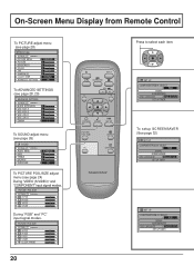
...COMPONENT/RGB-IN SELECT RGB SIGNAL SCREENSAVER OSD LANGUAGE ENGLISH (US) SET UP TIMER PICTURE POS./SIZE NORMALIZE H-POS H-SIZE V-POS V-SIZE NORMAL During "RGB" and "PC" input signal modes. On-Screen Menu Display from Remote Control To PICTURE adjust menu (see page 28) PICTURE NORMALIZE NORMAL PICTURE MENU PICTURE BRIGHTNESS COLOR TINT SHARPNESS COLOR TEMP ADVANCED SETTINGS STANDARD 0 0 0 0 0 NORMAL ON To ADVANCED SETTINGS (see page 28, 29) ADVANCED SETTINGS NORMALIZE NORMAL BLACK EXTENSION W/B HIGH R W/B HIGH B W/B LOW R W/B LOW B GAMMA 0 0 0 0 0 2. 2 To SOUND adjust menu (see...
...COMPONENT/RGB-IN SELECT RGB SIGNAL SCREENSAVER OSD LANGUAGE ENGLISH (US) SET UP TIMER PICTURE POS./SIZE NORMALIZE H-POS H-SIZE V-POS V-SIZE NORMAL During "RGB" and "PC" input signal modes. On-Screen Menu Display from Remote Control To PICTURE adjust menu (see page 28) PICTURE NORMALIZE NORMAL PICTURE MENU PICTURE BRIGHTNESS COLOR TINT SHARPNESS COLOR TEMP ADVANCED SETTINGS STANDARD 0 0 0 0 0 NORMAL ON To ADVANCED SETTINGS (see page 28, 29) ADVANCED SETTINGS NORMALIZE NORMAL BLACK EXTENSION W/B HIGH R W/B HIGH B W/B LOW R W/B LOW B GAMMA 0 0 0 0 0 2. 2 To SOUND adjust menu (see...

Installation Guide
Page 21
... Note: "SIGNAL" setup menu displays a different setting condition for each input signal. (see page 30) SET UP TIMER PRESENT TIME 0:52 POWER ON FUNCTION OFF POWER ON TIME 0:00 POWER OFF FUNCTION OFF POWER OFF TIME 0:00 Press to select each TIMER adjustment items. Press to display each TIME adjust screen. To SET UP TIMER selection screen.(see page 19) SCREENSAVER FUNCTION MODE START TIME FINISH TIME SIDE BAR ADJUST WHITE BAR...
... Note: "SIGNAL" setup menu displays a different setting condition for each input signal. (see page 30) SET UP TIMER PRESENT TIME 0:52 POWER ON FUNCTION OFF POWER ON TIME 0:00 POWER OFF FUNCTION OFF POWER OFF TIME 0:00 Press to select each TIMER adjustment items. Press to display each TIME adjust screen. To SET UP TIMER selection screen.(see page 19) SCREENSAVER FUNCTION MODE START TIME FINISH TIME SIDE BAR ADJUST WHITE BAR...

Installation Guide
Page 22
...), 525p (480p) and 625p (575p) signal input during "COMPONENT" input signal mode, the mode is set to enjoy viewing the picture at its maximum size, including wide screen cinema format picture. PC OFF TIMER PLASMA DISPLAY 22 INPUT SURROUND VOL N R PICTURE SOUND SET UP PICTURE POS. /SIZE ASPECT ASPECT ASPECT button The aspect mode changes each input terminal (VIDEO (S VIDEO), COMPONENT, RGB and PC). NORMAL ZOOM FULL AUTO JUST Notes: (1) During RGB and PC input signal modes, the mode switches between "NORMAL", "ZOOM" and "FULL...
...), 525p (480p) and 625p (575p) signal input during "COMPONENT" input signal mode, the mode is set to enjoy viewing the picture at its maximum size, including wide screen cinema format picture. PC OFF TIMER PLASMA DISPLAY 22 INPUT SURROUND VOL N R PICTURE SOUND SET UP PICTURE POS. /SIZE ASPECT ASPECT ASPECT button The aspect mode changes each input terminal (VIDEO (S VIDEO), COMPONENT, RGB and PC). NORMAL ZOOM FULL AUTO JUST Notes: (1) During RGB and PC input signal modes, the mode switches between "NORMAL", "ZOOM" and "FULL...

Installation Guide
Page 24
... received, the picture position will shift up or down. PICTURE SOUND SET UP PICTURE POS. /SIZE ASPECT PC OFF TIMER PLASMA DISPLAY R Press to adjust POS./SIZE. Adjusting PICTURE POSITION/SIZE Adjusting screen 1 PICTURE POS. /SIZE Press to display the PICTURE POS./ SIZE menu. 2 Press to select H-POS/H-SIZE/V-POS/ V-SIZE/CLOCK PHASE. This picture position movement cannot be controlled by the PICTURE POS./SIZE function. 24 Notes: (1) Adjustment details are memorized separately for different input signal formats (Adjustments for component signals are memorized for...
... received, the picture position will shift up or down. PICTURE SOUND SET UP PICTURE POS. /SIZE ASPECT PC OFF TIMER PLASMA DISPLAY R Press to adjust POS./SIZE. Adjusting PICTURE POSITION/SIZE Adjusting screen 1 PICTURE POS. /SIZE Press to display the PICTURE POS./ SIZE menu. 2 Press to select H-POS/H-SIZE/V-POS/ V-SIZE/CLOCK PHASE. This picture position movement cannot be controlled by the PICTURE POS./SIZE function. 24 Notes: (1) Adjustment details are memorized separately for different input signal formats (Adjustments for component signals are memorized for...

Installation Guide
Page 26
SOUND Adjustment 1 SOUND Press to display the Sound menu. 2 Select to adjust each SOUND mode (STANDARD, AUTO). Press to mute the sound. Sound is also reactivated when power is turned off or volume level is pressed during "NORMALIZE", then all adjustment values are memorized separately for each item. INPUT SURROUND VOL N R PICTURE SOUND SET UP BASS Adjusts low sounds TREBLE Adjusts high sounds BALANCE Adjusts left and right volumes SOUND NORMALIZE NORMAL AUDIO MENU BASS TREBLE BALANCE SURROUND SURROUND (see...
SOUND Adjustment 1 SOUND Press to display the Sound menu. 2 Select to adjust each SOUND mode (STANDARD, AUTO). Press to mute the sound. Sound is also reactivated when power is turned off or volume level is pressed during "NORMALIZE", then all adjustment values are memorized separately for each item. INPUT SURROUND VOL N R PICTURE SOUND SET UP BASS Adjusts low sounds TREBLE Adjusts high sounds BALANCE Adjusts left and right volumes SOUND NORMALIZE NORMAL AUDIO MENU BASS TREBLE BALANCE SURROUND SURROUND (see...

Installation Guide
Page 28
... COOL WARM Helpful Hint ( N / NORMALIZE Normalization) While the "PICTURE" menu is displayed, if either the N button on the remote control is pressed at any time or the (ACTION button) is pressed during "NORMALIZE", then all adjustment values are returned to adjust. ADVANCED SETTINGS NORMALIZE NORMAL BLACK EXTENSION W/B HIGH R W/B HIGH B W/B LOW R W/B LOW B GAMMA 0 0 0 0 0 2. 2 ADVANCED SETTINGS OFF Displays images with settings of the selected PICTURE menu to something else, adjust using the...
... COOL WARM Helpful Hint ( N / NORMALIZE Normalization) While the "PICTURE" menu is displayed, if either the N button on the remote control is pressed at any time or the (ACTION button) is pressed during "NORMALIZE", then all adjustment values are returned to adjust. ADVANCED SETTINGS NORMALIZE NORMAL BLACK EXTENSION W/B HIGH R W/B HIGH B W/B LOW R W/B LOW B GAMMA 0 0 0 0 0 2. 2 ADVANCED SETTINGS OFF Displays images with settings of the selected PICTURE menu to something else, adjust using the...
Installation Guide
Page 30
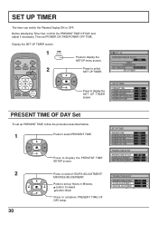
... to display the SET UP TIMER screen. Display the SET UP TIMER screen INPUT SURROUND VOL N R 1 SET UP 2 Press to display the PRESENT TIME SETUP screen. PRESENT TIME SETUP PRESENT TIME OF DAY 0 : 52 HOURS ADJUSTMENT 00 MINUTES ADJUSTMENT 52 Press to display the SETUP menu screen. button: Forward button: Back Press to select SET UP TIMER. SET UP COMPONENT/RGB-IN SELECT RGB SIGNAL SCREENSAVER OSD LANGUAGE ENGLISH (US) SET UP TIMER SET UP TIMER PRESENT TIME 0:52 POWER ON...
... to display the SET UP TIMER screen. Display the SET UP TIMER screen INPUT SURROUND VOL N R 1 SET UP 2 Press to display the PRESENT TIME SETUP screen. PRESENT TIME SETUP PRESENT TIME OF DAY 0 : 52 HOURS ADJUSTMENT 00 MINUTES ADJUSTMENT 52 Press to display the SETUP menu screen. button: Forward button: Back Press to select SET UP TIMER. SET UP COMPONENT/RGB-IN SELECT RGB SIGNAL SCREENSAVER OSD LANGUAGE ENGLISH (US) SET UP TIMER SET UP TIMER PRESENT TIME 0:52 POWER ON...

Installation Guide
Page 33
... of such an after -image to select the SIDE BAR ADJUST. In such an occurrence, use the Cinema mode. 33 Press to select HOURS ADJUSTMENT/ MINUTES ADJUSTMENT. Press to set . OFF DARK MID side bars 4:3 Screen Display BRIGHT after -images. • The side bar may result in 4:3 mode for an extended period may flash (alternate black/white) depending on the picture being shown on either side...
... of such an after -image to select the SIDE BAR ADJUST. In such an occurrence, use the Cinema mode. 33 Press to select HOURS ADJUSTMENT/ MINUTES ADJUSTMENT. Press to set . OFF DARK MID side bars 4:3 Screen Display BRIGHT after -images. • The side bar may result in 4:3 mode for an extended period may flash (alternate black/white) depending on the picture being shown on either side...
Installation Guide
Page 37
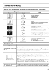
... of still pictures include logos, video games, computer images, teletext and images displayed in 4:3 mode. No Color Plasma Display panel Symptoms Normal Sound Color controls set at minimum level. (see page 28, 29) COLOR SYSTEM (see page 35) Check Some parts of the screen may be heard The display unit is fitted with a non-applicable color system format, or frequency is input, only the input terminal indication is displayed. Troubleshooting Before you call for service, determine...
... of still pictures include logos, video games, computer images, teletext and images displayed in 4:3 mode. No Color Plasma Display panel Symptoms Normal Sound Color controls set at minimum level. (see page 28, 29) COLOR SYSTEM (see page 35) Check Some parts of the screen may be heard The display unit is fitted with a non-applicable color system format, or frequency is input, only the input terminal indication is displayed. Troubleshooting Before you call for service, determine...

Installation Guide
Page 40
© 2003 VICTOR COMPANY OF JAPAN, LIMITED VICTOR COMPANY OF JAPAN, LIMITED Printed in Japan TQZW242 GD-V501U PLASMA DISPLAY MONITOR
© 2003 VICTOR COMPANY OF JAPAN, LIMITED VICTOR COMPANY OF JAPAN, LIMITED Printed in Japan TQZW242 GD-V501U PLASMA DISPLAY MONITOR


