

Instructions
Page 2
... the AC plug and power cord. 3. The exclamation point within the product's enclosure that contains a small amount of mercury. CAUTION: TO INSURE PERSONAL SAFETY, OBSERVE THE FOLLOWING RULES REGARDING THE USE OF THIS UNIT. 1. Disposal of important operating and maintenance (servicing) instructions in some components. Refer servicing to repair it yourself or remove the rear cover. Do not remove cover (or back). It...
... the AC plug and power cord. 3. The exclamation point within the product's enclosure that contains a small amount of mercury. CAUTION: TO INSURE PERSONAL SAFETY, OBSERVE THE FOLLOWING RULES REGARDING THE USE OF THIS UNIT. 1. Disposal of important operating and maintenance (servicing) instructions in some components. Refer servicing to repair it yourself or remove the rear cover. Do not remove cover (or back). It...

Instructions
Page 4
...) Unplug this apparatus during operation. L/MONO R AUDIO 17) Cautions for help. 4 These limits are designed to qualified service personnel. Reorient or relocate the receiving antenna. - Consult the dealer or an experienced radio/TV technician for installation - This equipment generates, uses and can be placed on , the user is connected. - Servicing is impossible. Install the TV in a particular installation. Keep to keep cords out of heat during lightning...
...) Unplug this apparatus during operation. L/MONO R AUDIO 17) Cautions for help. 4 These limits are designed to qualified service personnel. Reorient or relocate the receiving antenna. - Consult the dealer or an experienced radio/TV technician for installation - This equipment generates, uses and can be placed on , the user is connected. - Servicing is impossible. Install the TV in a particular installation. Keep to keep cords out of heat during lightning...

Instructions
Page 6
... dark, cooling is performed for approximately 1 minute at approximately every 2 seconds, and then goes out. Do not block the ventilation holes while the power is turned on the screen disappears. The lamp is being shut down. For a detailed explanation on is explained below . 1. Warnings Thank you for purchasing JVC's model HD-52G886, HD-52G786, HD-56G886 or HD-56G786 HDTV-ready projection television which the TV is being used as a guide...
... dark, cooling is performed for approximately 1 minute at approximately every 2 seconds, and then goes out. Do not block the ventilation holes while the power is turned on the screen disappears. The lamp is being shut down. For a detailed explanation on is explained below . 1. Warnings Thank you for purchasing JVC's model HD-52G886, HD-52G786, HD-56G886 or HD-56G786 HDTV-ready projection television which the TV is being used as a guide...

Instructions
Page 8
... Setup 40 Auto Tuner Setup 40 Channel Summary 41 Channel Label 42 V-Chip 43 Set Lock Code 49 Auto Demo 50 Language 50 Closed Caption 51 Auto Shut Off 53 XDS ID 53 Noise Muting 53 Front Panel Lock 54 V1 Smart Input 54 Video Input Label 55 Position Adjustment 56 Power Indicator 56 Video-1 Monitor Out 57 TV Speaker 57 Audio Out 57 Digital-In 58 Digital-In Audio 58 Center CH Input 59 Picture Adjust 60 Picture Settings 60 Adjust Picture Settings 60 Color Temperature 60 Digital Noise Clear 61 Color...
... Setup 40 Auto Tuner Setup 40 Channel Summary 41 Channel Label 42 V-Chip 43 Set Lock Code 49 Auto Demo 50 Language 50 Closed Caption 51 Auto Shut Off 53 XDS ID 53 Noise Muting 53 Front Panel Lock 54 V1 Smart Input 54 Video Input Label 55 Position Adjustment 56 Power Indicator 56 Video-1 Monitor Out 57 TV Speaker 57 Audio Out 57 Digital-In 58 Digital-In Audio 58 Center CH Input 59 Picture Adjust 60 Picture Settings 60 Adjust Picture Settings 60 Color Temperature 60 Digital Noise Clear 61 Color...

Instructions
Page 10
... your TV Thank you have all of the following items. In addition to make sure you for your television box should include: Television x 1 Remote Control x 1 AA Batteries x 2 AA Alkaline AA Alkaline TV CATV VCR DVD POWER ASPECT MULTI SCREEN TWIN INDEX SELECT SLEEP FREEZE SWAP ML/MTS DISPLAY + INPUT 123 D/A 4 5 6 i.LINK MENU 78 TIMER TUNE THEATER FAVORITE PRO 0 VIDEO STATUS C.C. Two Way Splitter x 1 2-WAY SPLITTER RF Cables...
... your TV Thank you have all of the following items. In addition to make sure you for your television box should include: Television x 1 Remote Control x 1 AA Batteries x 2 AA Alkaline AA Alkaline TV CATV VCR DVD POWER ASPECT MULTI SCREEN TWIN INDEX SELECT SLEEP FREEZE SWAP ML/MTS DISPLAY + INPUT 123 D/A 4 5 6 i.LINK MENU 78 TIMER TUNE THEATER FAVORITE PRO 0 VIDEO STATUS C.C. Two Way Splitter x 1 2-WAY SPLITTER RF Cables...

Instructions
Page 12
... CABLE IN I DIGITAL IN AV COMPULINK III VIDEO (DIGITAL) _ AUDIO (DIGITAL) CABLE CARD CENTER CHANNEL INPUT INPUT-2 Y VIDEO L AUDIO R S-VIDEO Pb Pr S-VIDEO L AUDIO R OVER VIDEO L I AUDIO I R OVER Y VIDEO L Pb I AUDIO I R Pr INPUT-3 INPUT-1 i.LINK IN/OUT S400(TS) OPTICAL OUT Digital Audio S-VIDEO VIDEO L AUDIO PC IN (D-SUB) L AUDIO OUTPUT 75Ω (VHF/UHF) R R MONITOR /REC OUT LICENSED UNDER THE FOLLOWING U.S. Rear Panel Diagram MODELS: HD-52G886 HD-52G786 HD-56G886 HD-56G786 Note: The terminal labeled "SERVICE ONLY", is exclusively used to update the software...
... CABLE IN I DIGITAL IN AV COMPULINK III VIDEO (DIGITAL) _ AUDIO (DIGITAL) CABLE CARD CENTER CHANNEL INPUT INPUT-2 Y VIDEO L AUDIO R S-VIDEO Pb Pr S-VIDEO L AUDIO R OVER VIDEO L I AUDIO I R OVER Y VIDEO L Pb I AUDIO I R Pr INPUT-3 INPUT-1 i.LINK IN/OUT S400(TS) OPTICAL OUT Digital Audio S-VIDEO VIDEO L AUDIO PC IN (D-SUB) L AUDIO OUTPUT 75Ω (VHF/UHF) R R MONITOR /REC OUT LICENSED UNDER THE FOLLOWING U.S. Rear Panel Diagram MODELS: HD-52G886 HD-52G786 HD-56G886 HD-56G786 Note: The terminal labeled "SERVICE ONLY", is exclusively used to update the software...

Instructions
Page 14
If your TV is connected to an ATSC antenna or Digital Cable, you can use these buttons. 14 Quick Setup TV Remote Control TV CATV VCR DVD POWER ASPECT MULTI SCREEN TWIN INDEX SELECT SLEEP FREEZE SWAP ML/MTS DISPLAY + INPUT 123 D/A 4 5 6 i.LINK MENU 78 TIMER TUNE THEATER FAVORITE PRO 0 VIDEO STATUS C.C. NATURAL SOUND CINEMA 9 RETURN+ TV SUB CHANNEL SUB LIGHT MUTING CH GUIDE VOL OK VOL CH MENU VCR CHANNEL PREV NEXT BACK VCR DVD POWER TV VCR REW PLAY FF...
If your TV is connected to an ATSC antenna or Digital Cable, you can use these buttons. 14 Quick Setup TV Remote Control TV CATV VCR DVD POWER ASPECT MULTI SCREEN TWIN INDEX SELECT SLEEP FREEZE SWAP ML/MTS DISPLAY + INPUT 123 D/A 4 5 6 i.LINK MENU 78 TIMER TUNE THEATER FAVORITE PRO 0 VIDEO STATUS C.C. NATURAL SOUND CINEMA 9 RETURN+ TV SUB CHANNEL SUB LIGHT MUTING CH GUIDE VOL OK VOL CH MENU VCR CHANNEL PREV NEXT BACK VCR DVD POWER TV VCR REW PLAY FF...

Instructions
Page 15
... CH JVC's onscreen menu system. The Remote Control Before you can be reset. If you turn the volume up or down towards the bottom of five channels per second. The channels will light blue. Move the switch to CATV only if you change the batteries, try to install the batteries (included). Please see page 93. 15 POWER T TV CATV MUL VCR DVD Note: • If the lamp replacement message...
... CH JVC's onscreen menu system. The Remote Control Before you can be reset. If you turn the volume up or down towards the bottom of five channels per second. The channels will light blue. Move the switch to CATV only if you change the batteries, try to install the batteries (included). Please see page 93. 15 POWER T TV CATV MUL VCR DVD Note: • If the lamp replacement message...

Instructions
Page 20
... the proper video input. • The AV CompuLink cable may be included with the JVC AV CompuLink unit you push the VCR's PLAY button. • If your JVC brand VCR has "A code/B code remote control switching" (see the receiver connection instructions for part # EWP 805-012. • AV CompuLink can only be removed from the VHS tape. AV COMPULINK III VIDEO (DIGITAL) _ AUDIO (DIGITAL) IN V L R IN OUT OUT TV Rear Panel AV CompuLink...
... the proper video input. • The AV CompuLink cable may be included with the JVC AV CompuLink unit you push the VCR's PLAY button. • If your JVC brand VCR has "A code/B code remote control switching" (see the receiver connection instructions for part # EWP 805-012. • AV CompuLink can only be removed from the VHS tape. AV COMPULINK III VIDEO (DIGITAL) _ AUDIO (DIGITAL) IN V L R IN OUT OUT TV Rear Panel AV CompuLink...

Instructions
Page 24
... connection, set DIGITAL-IN AUDIO in their digital form. Quick Setup Connections Connecting to a Digital TV Receiver By connecting a Digital TV Receiver, high definition pictures can be displayed on the screen, the horizontal balance may be slightly shifted. Notes: • If 480p signals (640x480 or 720x480) are displayed on your television. • The digital-in terminal is not compatible with a DTV decoder. TV Rear Panel AUDIO OUT LR DTV Decoder DIGITAL OUT AV COMPULINK III VIDEO (DIGITAL) _ AUDIO (DIGITAL) HDMI to DVI Cable L AUDIO R After the connections...
... connection, set DIGITAL-IN AUDIO in their digital form. Quick Setup Connections Connecting to a Digital TV Receiver By connecting a Digital TV Receiver, high definition pictures can be displayed on the screen, the horizontal balance may be slightly shifted. Notes: • If 480p signals (640x480 or 720x480) are displayed on your television. • The digital-in terminal is not compatible with a DTV decoder. TV Rear Panel AUDIO OUT LR DTV Decoder DIGITAL OUT AV COMPULINK III VIDEO (DIGITAL) _ AUDIO (DIGITAL) HDMI to DVI Cable L AUDIO R After the connections...

Instructions
Page 25
... III VIDEO (DIGITAL) _ AUDIO (DIGITAL) L AUDIO R HDMI Cable TV Rear Panel 1) Connect the HDMI Cable from the DIGITAL OUT on the back of your TV in the Initial Setup menu to the DIGITAL-IN on the back of your DTV or HDMI device, to DIGITAL. HDMI (High Definition Multimedia Interface) is changed to an HDMI Compatible Device By connecting an HDMI compatible device, high definition pictures can include DVD players, D-VHS or any audio/video source, such as a set DIGITAL-IN AUDIO in their digital form...
... III VIDEO (DIGITAL) _ AUDIO (DIGITAL) L AUDIO R HDMI Cable TV Rear Panel 1) Connect the HDMI Cable from the DIGITAL OUT on the back of your TV in the Initial Setup menu to the DIGITAL-IN on the back of your DTV or HDMI device, to DIGITAL. HDMI (High Definition Multimedia Interface) is changed to an HDMI Compatible Device By connecting an HDMI compatible device, high definition pictures can include DVD players, D-VHS or any audio/video source, such as a set DIGITAL-IN AUDIO in their digital form...

Instructions
Page 26
... television. AV Receiver MONITOR OUT Y PB PR MONITOR OUT S-VIDEO OVER Y VIDEO L Pb I AUDIO I R Pr INPUT-1 TV Rear Panel 1) Connect an S-Video Cable from the AV Receiver's PB MONITOR OUT, into the Pb VIDEO INPUT-1 on the back of your TV. This allows you to free up the other input connections so you can watch picture sources from many different devices, without having to change or use the other devices like a DVD player. • Use your AV Receiver's remote to switch...
... television. AV Receiver MONITOR OUT Y PB PR MONITOR OUT S-VIDEO OVER Y VIDEO L Pb I AUDIO I R Pr INPUT-1 TV Rear Panel 1) Connect an S-Video Cable from the AV Receiver's PB MONITOR OUT, into the Pb VIDEO INPUT-1 on the back of your TV. This allows you to free up the other input connections so you can watch picture sources from many different devices, without having to change or use the other devices like a DVD player. • Use your AV Receiver's remote to switch...

Instructions
Page 31
... Savings Time) To turn D.S.T. can be continued...) 31 You must set the clock using the XDS signal: SET CLOCK √® † To choose AUTO To TIME ZONE MODE TIME TIME ZONE DATE/YEAR D.S.T. SET CLOCK MODE TIME TIME ZONE DATE/YEAR D.S.T. Quick Setup Plug-In Menu Auto Clock Set Before you use any of your TV's timer functions, you must first set your clock manually (without using the XDS signal), choose MANUAL. NEXT AUTO -- : -- -- Manual Clock Set To set the...
... Savings Time) To turn D.S.T. can be continued...) 31 You must set the clock using the XDS signal: SET CLOCK √® † To choose AUTO To TIME ZONE MODE TIME TIME ZONE DATE/YEAR D.S.T. SET CLOCK MODE TIME TIME ZONE DATE/YEAR D.S.T. Quick Setup Plug-In Menu Auto Clock Set Before you use any of your TV's timer functions, you must first set your clock manually (without using the XDS signal), choose MANUAL. NEXT AUTO -- : -- -- Manual Clock Set To set the...

Instructions
Page 38
... list. Use the arrows √ ® to your television's operation simply and quickly. Notes: • If you press the up or down arrow at the bottom, the next menu screen will close the onscreen menu system and return you make adjustments to select an option from the highlighted feature. Channel and volume functions will be discussed in this guide. Selected Option (Green) LANGUAGE CLOSED CAPTION...
... list. Use the arrows √ ® to your television's operation simply and quickly. Notes: • If you press the up or down arrow at the bottom, the next menu screen will close the onscreen menu system and return you make adjustments to select an option from the highlighted feature. Channel and volume functions will be discussed in this guide. Selected Option (Green) LANGUAGE CLOSED CAPTION...

Instructions
Page 39
... picture signal is input to the digital-in terminal and the picture is being displayed on the screen. • When the Menu button on the TV side panel is pressed, the FRONT PANEL CONTROL menu between INITIAL SETUP 05 and PICTURE ADJUST 01 will appear. • Regarding the digital setup menu, see page 78. 39 Press the MENU button TO INITIAL SETUP 03 Onscreen Menus INITIAL SETUP PREVIOUS AUTO TUNER SETUP CHANNEL SUMMARY V-CHIP SET LOCK CODE AUTO DEMO OFF NEXT PAGE SELECT OPERATE (4/5) MENU...
... picture signal is input to the digital-in terminal and the picture is being displayed on the screen. • When the Menu button on the TV side panel is pressed, the FRONT PANEL CONTROL menu between INITIAL SETUP 05 and PICTURE ADJUST 01 will appear. • Regarding the digital setup menu, see page 78. 39 Press the MENU button TO INITIAL SETUP 03 Onscreen Menus INITIAL SETUP PREVIOUS AUTO TUNER SETUP CHANNEL SUMMARY V-CHIP SET LOCK CODE AUTO DEMO OFF NEXT PAGE SELECT OPERATE (4/5) MENU...

Instructions
Page 60
... the next setting Press the MENU button when finished PICTURE ADJUST PREVIOUS STANDARD TINT 00 COLOR 00 PICTURE 00 BRIGHT 00 DETAIL 00 COLOR TEMPERATURE HIGH NEXT PAGE (1/2) SELECT OPERATE MENU EXIT Color Temperature You can adjust the overall brightness of red and green in your television. COLOR The color function lets you make all the colors in the picture. Picture Adjust Picture Settings These settings allow you to change and adjust the way the picture appears on the TV screen, giving...
... the next setting Press the MENU button when finished PICTURE ADJUST PREVIOUS STANDARD TINT 00 COLOR 00 PICTURE 00 BRIGHT 00 DETAIL 00 COLOR TEMPERATURE HIGH NEXT PAGE (1/2) SELECT OPERATE MENU EXIT Color Temperature You can adjust the overall brightness of red and green in your television. COLOR The color function lets you make all the colors in the picture. Picture Adjust Picture Settings These settings allow you to change and adjust the way the picture appears on the TV screen, giving...
Instructions
Page 66
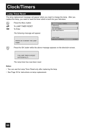
... can use the Lamp Timer Reset only after replacing the lamp. • See Page 93 for instructions on the television screen. After you replace the lamp, you need to change the lamp. NEXT PAGE SELECT OPERATE MENU EXIT Press the OK button while the above message appears on lamp replacement. 66 CLOCK / TIMERS PREVIOUS SET CLOCK ON / OFF TIMER LAMP TIMER RESET PRESS OK TO RESET THE LAMP TIMER. THE LAMP TIMER IS RESET SUCCESSFULLY. The lamp timer has now been reset. Clock/Timers Lamp Timer Reset The lamp replacement...
... can use the Lamp Timer Reset only after replacing the lamp. • See Page 93 for instructions on the television screen. After you replace the lamp, you need to change the lamp. NEXT PAGE SELECT OPERATE MENU EXIT Press the OK button while the above message appears on lamp replacement. 66 CLOCK / TIMERS PREVIOUS SET CLOCK ON / OFF TIMER LAMP TIMER RESET PRESS OK TO RESET THE LAMP TIMER. THE LAMP TIMER IS RESET SUCCESSFULLY. The lamp timer has now been reset. Clock/Timers Lamp Timer Reset The lamp replacement...

Instructions
Page 67
... work with locked channels or channels blocked by pressing TWIN on the right. The channel (or input) you press the menu button, only the picture adjust screen will continue to normal television viewing, press TWIN again or press the BACK button. 07 V-1 MAIN SCREEN PICTURE SPLIT SCREEN PICTURE Notes: • If the signal that you are in PC mode, TWIN, INDEX or FREEZE can not be displayed. • The aspect of MAIN CHANNEL PICTURE...
... work with locked channels or channels blocked by pressing TWIN on the right. The channel (or input) you press the menu button, only the picture adjust screen will continue to normal television viewing, press TWIN again or press the BACK button. 07 V-1 MAIN SCREEN PICTURE SPLIT SCREEN PICTURE Notes: • If the signal that you are in PC mode, TWIN, INDEX or FREEZE can not be displayed. • The aspect of MAIN CHANNEL PICTURE...

Instructions
Page 89
.../Off Timer is damaged, replace it may be due to a coaxial cable connection which is poor There are still working . There is snowy (image noise) • Your antenna may not have been programmed. Adjust your dealer. See page 72. Stereo or bilingual programs can reflect the original signal and produce a second, slightly delayed one. LED continues blinking 89 Screen is 80% black • The Closed Caption Text mode is...
.../Off Timer is damaged, replace it may be due to a coaxial cable connection which is poor There are still working . There is snowy (image noise) • Your antenna may not have been programmed. Adjust your dealer. See page 72. Stereo or bilingual programs can reflect the original signal and produce a second, slightly delayed one. LED continues blinking 89 Screen is 80% black • The Closed Caption Text mode is...

Instructions
Page 98
... compatible with picture signals of the TV set . HDMI jack x 1 Note: The Digital-In terminal is available. Power Source Power Consumption Projection Source Screen Size Speakers Audio Output Antenna Terminal (VHF/UHF, ATSC/DIGITAL CABLE IN) External Input Jacks Component Input Jack S-Video Input Jacks Monitor/Recording Output Audio Output Jacks (VARI/FIX) Optical Output Digital Audio i.LINK In/Out Jack AV CompuLink III Jack PC Input Jack Digital-In Dimensions (inch) W X H X D (cm) Weight (lbs / kg) Accessories AC 120V, 60 Hz 205W 110W High-Pressure Mercury Lamp 52 inch / 132...
... compatible with picture signals of the TV set . HDMI jack x 1 Note: The Digital-In terminal is available. Power Source Power Consumption Projection Source Screen Size Speakers Audio Output Antenna Terminal (VHF/UHF, ATSC/DIGITAL CABLE IN) External Input Jacks Component Input Jack S-Video Input Jacks Monitor/Recording Output Audio Output Jacks (VARI/FIX) Optical Output Digital Audio i.LINK In/Out Jack AV CompuLink III Jack PC Input Jack Digital-In Dimensions (inch) W X H X D (cm) Weight (lbs / kg) Accessories AC 120V, 60 Hz 205W 110W High-Pressure Mercury Lamp 52 inch / 132...


