User Guide
Page 2
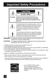
Refer servicing to repair it yourself or remove the rear cover. The lightning flash with an extension cord, receptacle or other outlet unless the blades can be fully inserted to prevent blade exposure. • As an "ENERGY STAR®" partner, JVC has determined that may be sure to disconnect both the power plug from the power source specified on the unit. 2. CAUTION...
Refer servicing to repair it yourself or remove the rear cover. The lightning flash with an extension cord, receptacle or other outlet unless the blades can be fully inserted to prevent blade exposure. • As an "ENERGY STAR®" partner, JVC has determined that may be sure to disconnect both the power plug from the power source specified on the unit. 2. CAUTION...
User Guide
Page 5
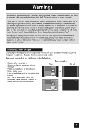
... able to view those channels you subscribe to scan or "surf". TV on your cable company for customers who subscribe to basic cable services (do not have a separate cable box) and plan to use their cable box and remote. Even though every channel is not a malfunction of time can contact your screen. Examples include, but it is receiving through the RF input), every channel number available from your television's Channel Summary and...
... able to view those channels you subscribe to scan or "surf". TV on your cable company for customers who subscribe to basic cable services (do not have a separate cable box) and plan to use their cable box and remote. Even though every channel is not a malfunction of time can contact your screen. Examples include, but it is receiving through the RF input), every channel number available from your television's Channel Summary and...

User Guide
Page 10
... AUDIO OUT Y VIDEO VIDEO PB L L L PR R R R Side Panel Diagram POWER INPUT 3 S-VIDEO Y VIDEO PB L PR R INPUT 4 INPUT 5 / INPUT 1 AUDIO AUDIO OUT Y VIDEO VIDEO PB L L L PR R R R 75 Ω (VHF/UHF) DIGITAL AUDIO INPUT 1 OPTICAL OUT INPUT 2 PHOTO VIEWER / SERVICE 75 Ω (VHF/UHF) DIGITAL AUDIO INPUT 1 OPTICAL OUT INPUT 2 PHOTO VIEWER / SERVICE INPUT MENU + CHANNEL - BACK POWER 10 These will help assist you connect your television to another device, as well as use the remote to the proper diagrams for your television. Quick Setup TV Models...
... AUDIO OUT Y VIDEO VIDEO PB L L L PR R R R Side Panel Diagram POWER INPUT 3 S-VIDEO Y VIDEO PB L PR R INPUT 4 INPUT 5 / INPUT 1 AUDIO AUDIO OUT Y VIDEO VIDEO PB L L L PR R R R 75 Ω (VHF/UHF) DIGITAL AUDIO INPUT 1 OPTICAL OUT INPUT 2 PHOTO VIEWER / SERVICE 75 Ω (VHF/UHF) DIGITAL AUDIO INPUT 1 OPTICAL OUT INPUT 2 PHOTO VIEWER / SERVICE INPUT MENU + CHANNEL - BACK POWER 10 These will help assist you connect your television to another device, as well as use the remote to the proper diagrams for your television. Quick Setup TV Models...

User Guide
Page 12
... is the first time you first need to remove. Raise the latch on the remote's back cover to begin using the four arrow keys. Next, select a menu using your remote control, you are used only for more detailed information on the TV, the interactive plug-in menu appears. POWER Using Menu Buttons To use the menu functions, press the MENU button. MENU BACK OK 12 The four arrow keys are turning on any...
... is the first time you first need to remove. Raise the latch on the remote's back cover to begin using the four arrow keys. Next, select a menu using your remote control, you are used only for more detailed information on the TV, the interactive plug-in menu appears. POWER Using Menu Buttons To use the menu functions, press the MENU button. MENU BACK OK 12 The four arrow keys are turning on any...

User Guide
Page 13
Quick Setup Step 2 - No VCR Connection Cable or Antenna Output Coaxial Cable TV Rear Panel 75 Ω (VHF/UHF) DIGITAL AUDIO INPUT 1 OPTICAL OUT INPUT 2 PHOTO VIEWER / SERVICE 13 Connecting your TV. Notes: • The following connection diagrams are examples. • After you are finished connecting your devices, plug the power cord into the nearest power outlet and turn on the TV. • If you follow these connections, you have a satellite television system, refer to connect audio/video devices like the ones illustrated...
Quick Setup Step 2 - No VCR Connection Cable or Antenna Output Coaxial Cable TV Rear Panel 75 Ω (VHF/UHF) DIGITAL AUDIO INPUT 1 OPTICAL OUT INPUT 2 PHOTO VIEWER / SERVICE 13 Connecting your TV. Notes: • The following connection diagrams are examples. • After you are finished connecting your devices, plug the power cord into the nearest power outlet and turn on the TV. • If you follow these connections, you have a satellite television system, refer to connect audio/video devices like the ones illustrated...

User Guide
Page 14
... best to complete one set of connections (DVD or audio output) before starting the other to avoid accidentally switching the cables. • You may vary colors. Quick Setup VCR • DVD Connection Notes: • Green, blue and red are the most common colors for more information. • Be careful not to Input 1. Please consult the user's manual for your DVD player for DVD cables. Diagram #1 R LV IN OUT VCR IN OUT Cable or Antenna Output OR Coaxial Cable AUDIO AUDIO AUDIO COMPONENT AUDIO COMPONENT INPUT 3 S-VIDEO Y VIDEO...
... best to complete one set of connections (DVD or audio output) before starting the other to avoid accidentally switching the cables. • You may vary colors. Quick Setup VCR • DVD Connection Notes: • Green, blue and red are the most common colors for more information. • Be careful not to Input 1. Please consult the user's manual for your DVD player for DVD cables. Diagram #1 R LV IN OUT VCR IN OUT Cable or Antenna Output OR Coaxial Cable AUDIO AUDIO AUDIO COMPONENT AUDIO COMPONENT INPUT 3 S-VIDEO Y VIDEO...

User Guide
Page 16
... sound model it to you televison by using the input jacks located on the back of the TV. Quick Setup Connecting to a Camcorder You can connect a camcorder to the LEFT AUDIO IN on the back of the television. TV Rear Panel CAMCORDER INPUT 3 S-VIDEO Y VIDEO PB L PR R INPUT 4 INPUT 5 / INPUT 1 AUDIO AUDIO OUT Y VIDEO VIDEO PB L L L PR R R R AUDIO AUDIO AUDIO COMPONENT AUDIO COMPONENT 1) Connect a yellow composite cable from the camcorder VIDEO OUT, into the VIDEO IN on the back of the TV. 2) Connect a white cable from the camcorder LEFT AUDIO...
... sound model it to you televison by using the input jacks located on the back of the TV. Quick Setup Connecting to a Camcorder You can connect a camcorder to the LEFT AUDIO IN on the back of the television. TV Rear Panel CAMCORDER INPUT 3 S-VIDEO Y VIDEO PB L PR R INPUT 4 INPUT 5 / INPUT 1 AUDIO AUDIO OUT Y VIDEO VIDEO PB L L L PR R R R AUDIO AUDIO AUDIO COMPONENT AUDIO COMPONENT 1) Connect a yellow composite cable from the camcorder VIDEO OUT, into the VIDEO IN on the back of the TV. 2) Connect a white cable from the camcorder LEFT AUDIO...
User Guide
Page 18
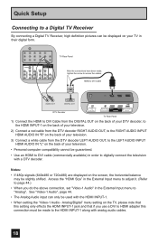
... signals (640x480 or 720x480) are displayed on the screen, the horizontal balance may be displayed on your television. • Personal computer compatibility cannot be used with analog audio cables. 18 Analog/Digital" menu setting on the back of your TV in their digital form. Quick Setup Connecting to a Digital TV Receiver By connecting a Digital TV Receiver, high definition pictures can only be guaranteed. • Use an HDMI to DVI cable (commercially available) in order to digitally connect the television with a DTV decoder. See "Video-1 Audio...
... signals (640x480 or 720x480) are displayed on the screen, the horizontal balance may be displayed on your television. • Personal computer compatibility cannot be used with analog audio cables. 18 Analog/Digital" menu setting on the back of your TV in their digital form. Quick Setup Connecting to a Digital TV Receiver By connecting a Digital TV Receiver, high definition pictures can only be guaranteed. • Use an HDMI to DVI cable (commercially available) in order to digitally connect the television with a DTV decoder. See "Video-1 Audio...

User Guide
Page 19
... the above connection, set -top box, DVD player, A/V receiver or an audio and/or video monitor, such as a set "Video-1 Audio" in their digital form. Quick Setup Connecting to an HDMI Compatible Device By connecting an HDMI compatible device, high definition pictures can be displayed on your TV in the External Input menu to 480p/60Hz), the screen may turn green and there may not respond depending on the back of your television. HDMI (High Definition Multimedia Interface) is changed to Digital. HDMI provides and...
... the above connection, set -top box, DVD player, A/V receiver or an audio and/or video monitor, such as a set "Video-1 Audio" in their digital form. Quick Setup Connecting to an HDMI Compatible Device By connecting an HDMI compatible device, high definition pictures can be displayed on your TV in the External Input menu to 480p/60Hz), the screen may turn green and there may not respond depending on the back of your television. HDMI (High Definition Multimedia Interface) is changed to Digital. HDMI provides and...

User Guide
Page 20
.../UHF) DIGITAL AUDIO INPUT 1 OPTICAL OUT INPUT 2 PHOTO VIEWER / SERVICE TV Rear Panel 1) Connect the optical cable from underneath the television to use the optical output connection, select PCM or DOLBY DIGITAL on using your amplifier. • You cannot output sound from the optical output. Notes: • This terminal can be PCM or DOLBY DIGITAL. See page 50. • Refer to your owners manual on Optical Out in the Sound Adjust Menu. The signal that is from your optical output You can connect an...
.../UHF) DIGITAL AUDIO INPUT 1 OPTICAL OUT INPUT 2 PHOTO VIEWER / SERVICE TV Rear Panel 1) Connect the optical cable from underneath the television to use the optical output connection, select PCM or DOLBY DIGITAL on using your amplifier. • You cannot output sound from the optical output. Notes: • This terminal can be PCM or DOLBY DIGITAL. See page 50. • Refer to your owners manual on Optical Out in the Sound Adjust Menu. The signal that is from your optical output You can connect an...

User Guide
Page 22
... "Auto Tuner Setup" Plug-in Menu automatically. Set Clock Mode Channel Time Time Zone D.S.T. can be used when it is set " Press the OK button Once you press OK, you choose "Auto", see auto clock set correctly depending on the broadcasting signal and receiving conditions. Set Clock Mode Channel Time Time Zone D.S.T. You must set the clock before operating any timer functions. You must set the clock before operating any timer functions. (Continued...) 22 Manual Clock Set To set your clock using "Auto (Digital)" for...
... "Auto Tuner Setup" Plug-in Menu automatically. Set Clock Mode Channel Time Time Zone D.S.T. can be used when it is set " Press the OK button Once you press OK, you choose "Auto", see auto clock set correctly depending on the broadcasting signal and receiving conditions. Set Clock Mode Channel Time Time Zone D.S.T. You must set the clock before operating any timer functions. You must set the clock before operating any timer functions. (Continued...) 22 Manual Clock Set To set your clock using "Auto (Digital)" for...
User Guide
Page 26
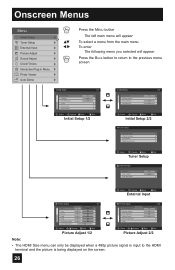
... Language Front Panel Lock V-Chip Set Lock Code Closed Caption On English Off Select BACK Operate Back MENU Exit Initial Setup 1/2 Initial Setup Auto Shut Off Software Version Power Indicator Quick Start-up 2/2 On Low On Select BACK Operate Back MENU Exit Initial Setup 2/2 - + Tuner Setup Auto Tuner Setup Channel Summary Find Channel Digital Antenna Level Select BACK Operate Back MENU Exit Tuner Setup External Input HDMI Size Video-1 Audio Video Input Label Auto Digital Select BACK Operate Back MENU Exit External Input Picture Adjust 1/2 Video Status Standard...
... Language Front Panel Lock V-Chip Set Lock Code Closed Caption On English Off Select BACK Operate Back MENU Exit Initial Setup 1/2 Initial Setup Auto Shut Off Software Version Power Indicator Quick Start-up 2/2 On Low On Select BACK Operate Back MENU Exit Initial Setup 2/2 - + Tuner Setup Auto Tuner Setup Channel Summary Find Channel Digital Antenna Level Select BACK Operate Back MENU Exit Tuner Setup External Input HDMI Size Video-1 Audio Video Input Label Auto Digital Select BACK Operate Back MENU Exit External Input Picture Adjust 1/2 Video Status Standard...
User Guide
Page 37
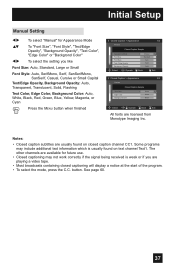
...Background Opacity: Auto, Transparent, Translucent, Solid, Flashing Text Color, Edge Color, Background Color: Auto, White, Black, Red, Green, Blue, Yellow, Magenta, or Cyan Press the MENU button when finished Closed Caption > Appearance 1/2 Preview Closed Caption Sample Appearance Mode Font Size Font Style Text / Edge Opacity Background Opacity Select Operate Manual Standard Auto Solid Solid BACK Back MENU Exit Closed Caption > Appearance 2/2 Preview Closed Caption Sample Text Color Edge Color Background Color White White Black Select OK BACK MENU Operate Back Exit...
...Background Opacity: Auto, Transparent, Translucent, Solid, Flashing Text Color, Edge Color, Background Color: Auto, White, Black, Red, Green, Blue, Yellow, Magenta, or Cyan Press the MENU button when finished Closed Caption > Appearance 1/2 Preview Closed Caption Sample Appearance Mode Font Size Font Style Text / Edge Opacity Background Opacity Select Operate Manual Standard Auto Solid Solid BACK Back MENU Exit Closed Caption > Appearance 2/2 Preview Closed Caption Sample Text Color Edge Color Background Color White White Black Select OK BACK MENU Operate Back Exit...

User Guide
Page 40
... "Video Status", "Aspect", "Auto Tuner Setup" and "Menu". appears onscreen. Notes: • When the Tuner Mode is set to "Cable", it is described on the side of the TV instead of the remote control. buttons ( √ OPERATE ® ). 40 Choose "Auto Tuner Setup" by pressing MENU† on the side panel and enter by using the CHANNEL +/- Tuner Setup Auto Tuner Setup The auto tuner setup function is possible to select "Scan Mode" • If no channels were found using Auto Tuner Setup, check your antenna cable and...
... "Video Status", "Aspect", "Auto Tuner Setup" and "Menu". appears onscreen. Notes: • When the Tuner Mode is set to "Cable", it is described on the side of the TV instead of the remote control. buttons ( √ OPERATE ® ). 40 Choose "Auto Tuner Setup" by pressing MENU† on the side panel and enter by using the CHANNEL +/- Tuner Setup Auto Tuner Setup The auto tuner setup function is possible to select "Scan Mode" • If no channels were found using Auto Tuner Setup, check your antenna cable and...

User Guide
Page 45
... default setting, π† to label video input connections for the onscreen displays. π† √® π† √® π† √® Press the MENU button To "External Input" To enter To "Video Input Label" To enter To select the desired video input To select the desired preset input label (see chart below) Press the MENU button when finished External Input HDMI Size Video-1 Audio Video Input Label Auto Digital Select BACK Operate Back MENU Exit External Input > Video Input...
... default setting, π† to label video input connections for the onscreen displays. π† √® π† √® π† √® Press the MENU button To "External Input" To enter To "Video Input Label" To enter To select the desired video input To select the desired preset input label (see chart below) Press the MENU button when finished External Input HDMI Size Video-1 Audio Video Input Label Auto Digital Select BACK Operate Back MENU Exit External Input > Video Input...
User Guide
Page 54
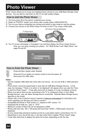
... containing your photos. 2) Switch to "PHOTO" mode if your device has a mode switch (VIDEO/PHOTO). 3) Turn on your device containing your photos and switch to play mode to view the photos. 4) Connect your device to turn the power off Disconnect the USB cable Notes: • Use the supplied USB cable that can enjoy viewing your device. JVC Everio Camera (Example) TV Rear Panel 75 Ω (VHF/UHF) DIGITAL AUDIO INPUT 1 OPTICAL OUT INPUT 2 PHOTO VIEWER / SERVICE USB Cable 5) The TV screen will appear when...
... containing your photos. 2) Switch to "PHOTO" mode if your device has a mode switch (VIDEO/PHOTO). 3) Turn on your device containing your photos and switch to play mode to view the photos. 4) Connect your device to turn the power off Disconnect the USB cable Notes: • Use the supplied USB cable that can enjoy viewing your device. JVC Everio Camera (Example) TV Rear Panel 75 Ω (VHF/UHF) DIGITAL AUDIO INPUT 1 OPTICAL OUT INPUT 2 PHOTO VIEWER / SERVICE USB Cable 5) The TV screen will appear when...

User Guide
Page 59
... be displayed. Program it to work for when you are playing video games connected to the factory settings. When you change the mode by pressing the π† buttons. • You can turn the TV off . Note: • You can also change the mode. Dynamic - Game - Used for a total time of the V. Sleep Timer The Sleep Timer can also access the "Front Menu" screen by using the CHANNEL +/- STATUS button, you press the SLEEP button once, the rest of the time will...
... be displayed. Program it to work for when you are playing video games connected to the factory settings. When you change the mode by pressing the π† buttons. • You can turn the TV off . Note: • You can also change the mode. Dynamic - Game - Used for a total time of the V. Sleep Timer The Sleep Timer can also access the "Front Menu" screen by using the CHANNEL +/- STATUS button, you press the SLEEP button once, the rest of the time will...
User Guide
Page 66
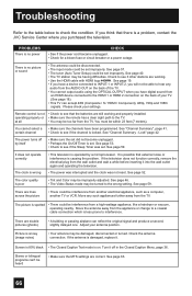
... the channels have digital sound from a high-wattage appliance, like a hairdryer or vacuum, operating nearby. If the antenna is on the back of the TV. • You cannot output audio using the OPTICAL OUTPUT when you will not be interference from an HDMI device connected to see if the Sleep Timer was not reset. Screen is 80% black • The Closed Caption Text mode is damaged, replace it. There is locked. See "Channel Summary...
... the channels have digital sound from a high-wattage appliance, like a hairdryer or vacuum, operating nearby. If the antenna is on the back of the TV. • You cannot output audio using the OPTICAL OUTPUT when you will not be interference from an HDMI device connected to see if the Sleep Timer was not reset. Screen is 80% black • The Closed Caption Text mode is damaged, replace it. There is locked. See "Channel Summary...
User Guide
Page 68
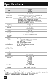
... your TV set 's on-screen cable channel numbers) is embedded in this product. Specifications Model Type Reception Format Reception Range Power Source Power Consumption Screen Size Audio Output Speakers Antenna Terminal (VHF/UHF, ATSC/DIGITAL CABLE IN) Input 3, 4, 5 Terminal Input 3, 4 Terminal (Component Terminal) Input 1, 2 Terminal (HDMI Input Terminal) Audio Output Jacks (FIX) Optical Output Digital Audio Dimensions (inch/cm) W X H X D Weight (lbs / kg) Accessories LT-32E488 LT-32E478 LT-32EX38 LCD Flat Television NTSC, BTSC System (Multi-Channel Sound) ATSC Terrestrial, Digital Cable...
... your TV set 's on-screen cable channel numbers) is embedded in this product. Specifications Model Type Reception Format Reception Range Power Source Power Consumption Screen Size Audio Output Speakers Antenna Terminal (VHF/UHF, ATSC/DIGITAL CABLE IN) Input 3, 4, 5 Terminal Input 3, 4 Terminal (Component Terminal) Input 1, 2 Terminal (HDMI Input Terminal) Audio Output Jacks (FIX) Optical Output Digital Audio Dimensions (inch/cm) W X H X D Weight (lbs / kg) Accessories LT-32E488 LT-32E478 LT-32EX38 LCD Flat Television NTSC, BTSC System (Multi-Channel Sound) ATSC Terrestrial, Digital Cable...
User Guide
Page 69
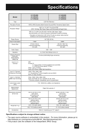
Specifications Model Type Reception Format Reception Range Power Source Power Consumption Screen Size Audio Output Speakers Antenna Terminal (VHF/UHF, ATSC/DIGITAL CABLE IN) Input 3, 4, 5 Terminal Input 3, 4 Terminal (Component Terminal) Input 1, 2 Terminal (HDMI Input Terminal) Audio Output Jacks (FIX) Optical Output Digital Audio Dimensions (inch/cm) W X H X D Weight (lbs / kg) Accessories LT-37E488 LT-37E478 LT-37EX38 LCD Flat Television LT-42E488 LT-42E478 LT-42EX38 NTSC, BTSC System (Multi-Channel Sound) ATSC Terrestrial, Digital Cable VHF 2 to 13, UHF 14 to 69 at ATSC, CATV 135...
Specifications Model Type Reception Format Reception Range Power Source Power Consumption Screen Size Audio Output Speakers Antenna Terminal (VHF/UHF, ATSC/DIGITAL CABLE IN) Input 3, 4, 5 Terminal Input 3, 4 Terminal (Component Terminal) Input 1, 2 Terminal (HDMI Input Terminal) Audio Output Jacks (FIX) Optical Output Digital Audio Dimensions (inch/cm) W X H X D Weight (lbs / kg) Accessories LT-37E488 LT-37E478 LT-37EX38 LCD Flat Television LT-42E488 LT-42E478 LT-42EX38 NTSC, BTSC System (Multi-Channel Sound) ATSC Terrestrial, Digital Cable VHF 2 to 13, UHF 14 to 69 at ATSC, CATV 135...


