
Instruction Manual
Page 5
... Midnight mode-MIDNIGHT MODE 19 Setting the digital input (DIGITAL IN) terminals -DIGITAL IN 1/2 20 Setting the Auto Function mode-AUTO MODE 20 Selecting the component video input mode -DVD VIDEO IN/VIDEO VIDEOIN 20 Sound... Using preset tuning 25 Selecting the FM reception mode 26 Using the Radio Data System (RDS) to receive FM stations 27 Searching for a program by PTY codes 28 Switching to broadcast program of your choice...34 Activating the Surround/DSP modes 35 Operating other JVC products 36 Operating other manufacturers' products ........ 38 Troubleshooting 41 Specifications 42 1
... Midnight mode-MIDNIGHT MODE 19 Setting the digital input (DIGITAL IN) terminals -DIGITAL IN 1/2 20 Setting the Auto Function mode-AUTO MODE 20 Selecting the component video input mode -DVD VIDEO IN/VIDEO VIDEOIN 20 Sound... Using preset tuning 25 Selecting the FM reception mode 26 Using the Radio Data System (RDS) to receive FM stations 27 Searching for a program by PTY codes 28 Switching to broadcast program of your choice...34 Activating the Surround/DSP modes 35 Operating other JVC products 36 Operating other manufacturers' products ........ 38 Troubleshooting 41 Specifications 42 1

Instruction Manual
Page 7
Front panel 1 2 345 AUDIO/VIDEO CONTROL RECEIVER STANDBY/ON DIMMER SETTING ADJUST SURROUND PHONES USB 6 ... : 6 DSP 3D-PHONIC VIRTUAL SB RDS TA NEWS INFO TUNED STEREO AUTO MUTING AUTO MODE DIGITAL EQ C.TONE B.BOOST SLEEP MIDNIGHT INPUT ATT MHz kHz ! @ #$ 1 ANALOG indicator (13) 2 DUAL MONO indicator (19) 3 AUTO SURR (surround) indicator (35...IMPEDANCE 6 -16 7 1 Power cord (11) 2 COMPONENT VIDEO (Y, PB, PR) jacks (8, 9) VIDEO IN, DVR/DVD IN, MONITOR OUT 3 AV IN/OUT terminals (7) TV, VCR, DVR/DVD 4 DIGITAL IN terminals (10) • Coaxial: 1(DVR/DVD) • Optical: 2(VIDEO) 5 ...
Front panel 1 2 345 AUDIO/VIDEO CONTROL RECEIVER STANDBY/ON DIMMER SETTING ADJUST SURROUND PHONES USB 6 ... : 6 DSP 3D-PHONIC VIRTUAL SB RDS TA NEWS INFO TUNED STEREO AUTO MUTING AUTO MODE DIGITAL EQ C.TONE B.BOOST SLEEP MIDNIGHT INPUT ATT MHz kHz ! @ #$ 1 ANALOG indicator (13) 2 DUAL MONO indicator (19) 3 AUTO SURR (surround) indicator (35...IMPEDANCE 6 -16 7 1 Power cord (11) 2 COMPONENT VIDEO (Y, PB, PR) jacks (8, 9) VIDEO IN, DVR/DVD IN, MONITOR OUT 3 AV IN/OUT terminals (7) TV, VCR, DVR/DVD 4 DIGITAL IN terminals (10) • Coaxial: 1(DVR/DVD) • Optical: 2(VIDEO) 5 ...
Instruction Manual
Page 10
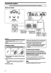
... Ω). • DO NOT connect more than one speaker to the (+) and (-) terminals marked on the rear panel to one surround back speaker. Connect the input jack of each speaker cord. 2 Open the terminal (1), then insert the speaker cord (2). • For each speaker, connect the (+) and (-) terminals on the speakers. 3 Close...
... Ω). • DO NOT connect more than one speaker to the (+) and (-) terminals marked on the rear panel to one surround back speaker. Connect the input jack of each speaker cord. 2 Open the terminal (1), then insert the speaker cord (2). • For each speaker, connect the (+) and (-) terminals on the speakers. 3 Close...

Instruction Manual
Page 11
...; Output Composite *1*2 *1*2 *1*2 Video S-video (Y/C) *2 − − RGB *2 − − T-V LINK *3 *3 *3 : Available, -: Not available *1 The signals input from this receiver may be distorted. AM EXT AV IN/OUT TV VCR DVR/DVD TV SCART cable (not supplied) DVD recorder or DVD player NOTES • Select the analogue... input mode. For example, if S-video signals are completed. Connecting video ...
...; Output Composite *1*2 *1*2 *1*2 Video S-video (Y/C) *2 − − RGB *2 − − T-V LINK *3 *3 *3 : Available, -: Not available *1 The signals input from this receiver may be distorted. AM EXT AV IN/OUT TV VCR DVR/DVD TV SCART cable (not supplied) DVD recorder or DVD player NOTES • Select the analogue... input mode. For example, if S-video signals are completed. Connecting video ...
Instruction Manual
Page 12
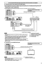
... supplied) NOTES • Do not connect different components to the AUDIO DVR/DVD IN jacks and AV IN/ OUT (SCART) DVR/DVD terminal (see page 10. • When connecting a DVD ...connections. For TV and video format This receiver cannot convert the video signals. If there is not an appropriate terminal for the decoder connection on the JVC's T-V LINK compatible TV for example, ...DVD player to the component video input jacks, select the component video input mode (DVD VIDEO IN) correctly. Audio/video connection In addition to the SCART terminals, this receiver with the TV and the VCR....
... supplied) NOTES • Do not connect different components to the AUDIO DVR/DVD IN jacks and AV IN/ OUT (SCART) DVR/DVD terminal (see page 10. • When connecting a DVD ...connections. For TV and video format This receiver cannot convert the video signals. If there is not an appropriate terminal for the decoder connection on the JVC's T-V LINK compatible TV for example, ...DVD player to the component video input jacks, select the component video input mode (DVD VIDEO IN) correctly. Audio/video connection In addition to the SCART terminals, this receiver with the TV and the VCR....
Instruction Manual
Page 13
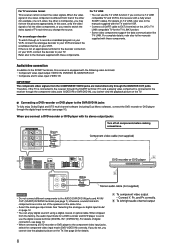
...(not supplied) Composite video cable (not supplied) S-video cable (not supplied) NOTES Å To component video output • Select the analogue input mode. For details of digital connection, see page 10. • When connecting a video component other than DVD recorder or DVD player to the...component video (Y, PB, PR) terminals, connect them using these jacks, select "VIDEO" as the source (see page 10. Å To component video input • Connect Y, PB, and PR correctly. 9 By using an S-video cable (not supplied) and/or component video cable (not supplied). Component ...
...(not supplied) Composite video cable (not supplied) S-video cable (not supplied) NOTES Å To component video output • Select the analogue input mode. For details of digital connection, see page 10. • When connecting a video component other than DVD recorder or DVD player to the...component video (Y, PB, PR) terminals, connect them using these jacks, select "VIDEO" as the source (see page 10. Å To component video input • Connect Y, PB, and PR correctly. 9 By using an S-video cable (not supplied) and/or component video cable (not supplied). Component ...
Instruction Manual
Page 14
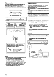
... A plug to their manuals. Turn on your PC. When the component has a digital optical output terminal, connect it to this receiver. See "Setting the digital input (DIGITAL IN) terminals-DIGITAL IN 1/2" on , quit all components before making connections. • When you connect other equipment. 4.... the volume to your PC equipped with the following procedure is running . 2. Connect the unit to the analogue connection methods described on the receiver, and select the source as "USB DIGITAL." 3. Turn on pages 7 to the 2(VIDEO) terminal, using a USB cable (not supplied...
... A plug to their manuals. Turn on your PC. When the component has a digital optical output terminal, connect it to this receiver. See "Setting the digital input (DIGITAL IN) terminals-DIGITAL IN 1/2" on , quit all components before making connections. • When you connect other equipment. 4.... the volume to your PC equipped with the following procedure is running . 2. Connect the unit to the analogue connection methods described on the receiver, and select the source as "USB DIGITAL." 3. Turn on pages 7 to the 2(VIDEO) terminal, using a USB cable (not supplied...
Instruction Manual
Page 16
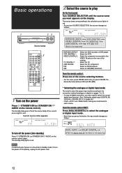
...remote control). Select the VCR. Current source name appears. AUDIO on the NOTE A small amount of digital connection, you also need to select the proper input mode according to 10. • In case of power is consumed in red. ANALOG AUTO SURR L R S.WFR TUNED STEREO AUTO MUTING MHz * ... source lamp corresponding to the selected source lights in red. Select an FM broadcast. Each time you want appears on the rear of the receiver. DGTL AUTO DOLBY DIGITAL DTS ANALOGUE (Back to the VIDEO IN jacks on the display. Select the component connected to the beginning) 12 ...
...remote control). Select the VCR. Current source name appears. AUDIO on the NOTE A small amount of digital connection, you also need to select the proper input mode according to 10. • In case of power is consumed in red. ANALOG AUTO SURR L R S.WFR TUNED STEREO AUTO MUTING MHz * ... source lamp corresponding to the selected source lights in red. Select an FM broadcast. Each time you want appears on the rear of the receiver. DGTL AUTO DOLBY DIGITAL DTS ANALOGUE (Back to the VIDEO IN jacks on the display. Select the component connected to the beginning) 12 ...
Instruction Manual
Page 17
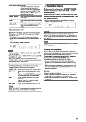
... multi-channel software.) Connect a pair of headphones from the speakers. 13 CAUTION: Always set at the beginning of signal comes into the receiver. If the volume is set the volume to the PHONES jack on the remote control). CAUTION: Be sure to turn MASTER VOLUME control ...you adjust the volume, the volume level indication appears on the display for any sources. DGTL AUTO (DIGITAL AUTO): Select for the analogue input mode. The receiver automatically detects the incoming signal format, then the digital signal format indicator (LINEAR PCM, , , or 96/24) for the detected signal...
... multi-channel software.) Connect a pair of headphones from the speakers. 13 CAUTION: Always set at the beginning of signal comes into the receiver. If the volume is set the volume to the PHONES jack on the remote control). CAUTION: Be sure to turn MASTER VOLUME control ...you adjust the volume, the volume level indication appears on the display for any sources. DGTL AUTO (DIGITAL AUTO): Select for the analogue input mode. The receiver automatically detects the incoming signal format, then the digital signal format indicator (LINEAR PCM, , , or 96/24) for the detected signal...

Instruction Manual
Page 18
... up when monaural surround signal comes in . Basic adjustment of auto memory This receiver memorizes sound settings for each source: • when you press the button, the display brightness changes as follows: L: • When digital input is selected: Lights up . Signal and speaker indicators on the display Signal indicators... (in minutes) until the shut-off time changes in . C: Lights up when the surround back channel signal comes in . • When analogue input is FM or AM (MW), you change the shut-off the receiver. LFE: Lights up when the right channel signal comes in .
... up when monaural surround signal comes in . Basic adjustment of auto memory This receiver memorizes sound settings for each source: • when you press the button, the display brightness changes as follows: L: • When digital input is selected: Lights up . Signal and speaker indicators on the display Signal indicators... (in minutes) until the shut-off time changes in . C: Lights up when the surround back channel signal comes in . • When analogue input is FM or AM (MW), you change the shut-off the receiver. LFE: Lights up when the right channel signal comes in .

Instruction Manual
Page 24
... the DVD recorder (or DVD player) to the component video input jacks. VIDEO Select when connecting the video component to the SCART input, the composite video or S-video input jacks. When the receiver is off , the receiver changes the source to the composite video or Svideo input jacks. Ex.: When "DIGITAL IN 1" is set to "DVR...
... the DVD recorder (or DVD player) to the component video input jacks. VIDEO Select when connecting the video component to the SCART input, the composite video or S-video input jacks. When the receiver is off , the receiver changes the source to the composite video or Svideo input jacks. Ex.: When "DIGITAL IN 1" is set to "DVR...

Instruction Manual
Page 25
...LIVENESS CENTER WIDTH CENTER GAIN CENTER ALIGN FRONT L LVL CENTER LVL SURR R LVL S BACK L LVL D EQ 63Hz D EQ 1kHz D EQ 16kHz INPUT ATT ROOM SIZE PANORAMA DIMENSION CENTER TONE (Back to adjust the selected item. Items SUBWFR LVL*1 FRONT L LVL*1*2 FRONT R LVL*1*2 CENTER LVL*1*2 SURR ... LVL*1*2 SURR R LVL*1*2 S BACK LVL*1*2 S BACK L LVL*1*2 S BACK R LVL*1*2 D EQ 63Hz*1 D EQ 250Hz*1 D EQ 1kHz*1 D EQ 4kHz*1 D EQ 16kHz*1 BASS BOOST INPUT ATT EFFECT*1 ROOM SIZE LIVENESS PANORAMA CENTER WIDTH DIMENSION CENTER GAIN CENTER TONE*1 To do Adjust the subwoofer output level. (22) Adjust the left front...
...LIVENESS CENTER WIDTH CENTER GAIN CENTER ALIGN FRONT L LVL CENTER LVL SURR R LVL S BACK L LVL D EQ 63Hz D EQ 1kHz D EQ 16kHz INPUT ATT ROOM SIZE PANORAMA DIMENSION CENTER TONE (Back to adjust the selected item. Items SUBWFR LVL*1 FRONT L LVL*1*2 FRONT R LVL*1*2 CENTER LVL*1*2 SURR ... LVL*1*2 SURR R LVL*1*2 S BACK LVL*1*2 S BACK L LVL*1*2 S BACK R LVL*1*2 D EQ 63Hz*1 D EQ 250Hz*1 D EQ 1kHz*1 D EQ 4kHz*1 D EQ 16kHz*1 BASS BOOST INPUT ATT EFFECT*1 ROOM SIZE LIVENESS PANORAMA CENTER WIDTH DIMENSION CENTER GAIN CENTER TONE*1 To do Adjust the subwoofer output level. (22) Adjust the left front...
Instruction Manual
Page 27
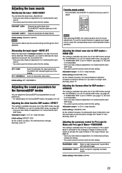
... After pressing SOUND, the numeric buttons work for the analogue or digital 2-channel sound signal. Initial setting: PANORAMA 23 Attenuating the input signal-INPUT ATT When the input level of the DSP modes (except ALL CH STEREO) is activated for sound adjustments. If this setting. Initial setting: ATT Adjusting..., it is memorized for each DSP mode. • You cannot use the remote control for this happens, you need to attenuate the input signal level to prevent the sound distortion. • Once you have made an adjustment, it is memorized until you have made an adjustment...
... After pressing SOUND, the numeric buttons work for the analogue or digital 2-channel sound signal. Initial setting: PANORAMA 23 Attenuating the input signal-INPUT ATT When the input level of the DSP modes (except ALL CH STEREO) is activated for sound adjustments. If this setting. Initial setting: ATT Adjusting..., it is memorized for each DSP mode. • You cannot use the remote control for this happens, you need to attenuate the input signal level to prevent the sound distortion. • Once you have made an adjustment, it is memorized until you have made an adjustment...

Instruction Manual
Page 35
... surround sound localization will become more detailed movements behind you while viewing the video software. Surround/DSP modes built in this receiver can create almost the same Surround sound as 0.1 channel. Dolby Digital enables stereo surround sounds, and sets the cutoff frequency ..., developed by Dolby Laboratories, and enables multi-channel encoding and decoding. • When Dolby Digital signal is detected through the digital input, the indicator lights up on the display. As such, the sound movement and "being-there" feeling are trademarks of Dolby Laboratories....
... surround sound localization will become more detailed movements behind you while viewing the video software. Surround/DSP modes built in this receiver can create almost the same Surround sound as 0.1 channel. Dolby Digital enables stereo surround sounds, and sets the cutoff frequency ..., developed by Dolby Laboratories, and enables multi-channel encoding and decoding. • When Dolby Digital signal is detected through the digital input, the indicator lights up on the display. As such, the sound movement and "being-there" feeling are trademarks of Dolby Laboratories....

Instruction Manual
Page 36
... and decoding (1ch up to 6.1ch). • When DTS signal is detected through the digital input, the indicator lights up on the display. DTS-ES Matrix 6.1ch has been designed to add an...channel software by using the high precision digital matrix decoder used for DTS-ES Matrix 6.1ch. • This receiver provides the following DTS Neo:6 modes-Neo:6 Cinema (NEO:6 CINEMA) and Neo:6 Music (NEO:6 MUSIC). DTS... and sub-channel) to be easily understood when you want to listen to (see page 17), JVC's original 3D-PHONIC processing (which enables it to add breadth and depth to the sounds reproduced....
... and decoding (1ch up to 6.1ch). • When DTS signal is detected through the digital input, the indicator lights up on the display. DTS-ES Matrix 6.1ch has been designed to add an...channel software by using the high precision digital matrix decoder used for DTS-ES Matrix 6.1ch. • This receiver provides the following DTS Neo:6 modes-Neo:6 Cinema (NEO:6 CINEMA) and Neo:6 Music (NEO:6 MUSIC). DTS... and sub-channel) to be easily understood when you want to listen to (see page 17), JVC's original 3D-PHONIC processing (which enables it to add breadth and depth to the sounds reproduced....
Instruction Manual
Page 39
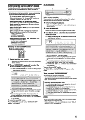
... "MONO FILM" is not available. *4 If "SURROUND SPK" is set to the beginning) *1 "AUTO SURROUND" is canceled before you have selected the input mode (analogue or digital) correctly. 2 Press SURROUND repeatedly to select the Surround/DSP mode you want . Ex.: When "DOLBY DIGITAL" is the initial setting...23) Selecting the Surround/DSP modes From the remote control: 2 1 1 Select and play any source. • Make sure you have selected the input mode (analogue or digital) correctly. 2 Press SURROUND. How does "AUTO SURROUND" work? • If a multi-channel signal comes in, an appropriate...
... "MONO FILM" is not available. *4 If "SURROUND SPK" is set to the beginning) *1 "AUTO SURROUND" is canceled before you have selected the input mode (analogue or digital) correctly. 2 Press SURROUND repeatedly to select the Surround/DSP mode you want . Ex.: When "DOLBY DIGITAL" is the initial setting...23) Selecting the Surround/DSP modes From the remote control: 2 1 1 Select and play any source. • Make sure you have selected the input mode (analogue or digital) correctly. 2 Press SURROUND. How does "AUTO SURROUND" work? • If a multi-channel signal comes in, an appropriate...

Instruction Manual
Page 40
... "A." - Start playback. Change the input mode (either video input or TV tuner) on the VCR. Change the channel numbers. CHANNEL +/-: 3: 7: 8: FF: REW: REC PAUSE: Change the channel numbers on the TV. Fast-wind a tape. Enter recording pause. Some JVC DVD recorders can accept four types of...can use the supplied remote control to operate not only this button then 3. Some JVC VCRs can accept two types of the control signals. Pause playback. To start recording, press this receiver but also other JVC products. • Refer also to the manuals supplied with the DVD recorder. ...
... "A." - Start playback. Change the input mode (either video input or TV tuner) on the VCR. Change the channel numbers. CHANNEL +/-: 3: 7: 8: FF: REW: REC PAUSE: Change the channel numbers on the TV. Fast-wind a tape. Enter recording pause. Some JVC DVD recorders can accept four types of...can use the supplied remote control to operate not only this button then 3. Some JVC VCRs can accept two types of the control signals. Pause playback. To start recording, press this receiver but also other JVC products. • Refer also to the manuals supplied with the DVD recorder. ...

Instruction Manual
Page 42
.... 4 Release STANDBY/ON TV/STB. After pressing TV, you need to the buttons in some equipment. ❏ Changing the transmittable signals for TV Manufacturer JVC Daewoo Grundig Panasonic Philips Samsung Sony Thomson Codes 01 03, 19, 20 02 06, 07 03 08, 09, 20 09, 10, 11, 12, 13...38 Manufacturers' codes for operating a TV 1 Press and hold STANDBY/ON TV/STB. 2 Press TV. 3 Enter the manufacturer's code using buttons 1 - 9, and 0. Change the input mode (either TV or VIDEO). When your brand of the remote control, set the manufacturers' codes again. • All the functions may not be assigned...
.... 4 Release STANDBY/ON TV/STB. After pressing TV, you need to the buttons in some equipment. ❏ Changing the transmittable signals for TV Manufacturer JVC Daewoo Grundig Panasonic Philips Samsung Sony Thomson Codes 01 03, 19, 20 02 06, 07 03 08, 09, 20 09, 10, 11, 12, 13...38 Manufacturers' codes for operating a TV 1 Press and hold STANDBY/ON TV/STB. 2 Press TV. 3 Enter the manufacturer's code using buttons 1 - 9, and 0. Change the input mode (either TV or VIDEO). When your brand of the remote control, set the manufacturers' codes again. • All the functions may not be assigned...

Instruction Manual
Page 45
...operation. Set the mode selector to 11) after doing solutions above, consult your JVC's service center. Select another station. Move the antenna farther from speakers. The receiver turns off the receiver for your dealer. Remote control does not operate as a lightning discharge. Select ...problems you cannot solve, contact your dealer after unplugging the power cord. An incorrect input mode (analogue or digital) is an obstruction hiding the remote sensor on the receiver. When you use the digital coaxial connection, the sounds may be intermittently distorted by...
...operation. Set the mode selector to 11) after doing solutions above, consult your JVC's service center. Select another station. Move the antenna farther from speakers. The receiver turns off the receiver for your dealer. Remote control does not operate as a lightning discharge. Select ...problems you cannot solve, contact your dealer after unplugging the power cord. An incorrect input mode (analogue or digital) is an obstruction hiding the remote sensor on the receiver. When you use the digital coaxial connection, the sounds may be intermittently distorted by...

Instruction Manual
Page 46
Video Video Input Sensitivity/Impedance: Composite video: DVR/DVD, VCR, VIDEO: 1 V(p-p)/75 Ω S-video: DVR/DVD, VCR, VIDEO: Y (luminance): C (chrominance, burst): RGB: DVR/DVD, VCR: 1 V(p-p)/75 Ω 0.3 V(p-p)/75 &#...;V/75 Ω) 21.3 dBf (3.2 µV/75 Ω) 41.3 dBf (31.8 µV/75 Ω) 35 dB at 1 kHz Audio Audio Input Sensitivity/Impedance: DVR/DVD, VCR, VIDEO, TV: 270 mV/47 kΩ Audio Input (DIGITAL IN)*: Coaxial: DIGITAL IN 1(DVR/DVD): 0.5 V(p-p)/75 Ω Optical: DIGITAL IN 2(VIDEO): -21 dBm to -15 dBm (660...
Video Video Input Sensitivity/Impedance: Composite video: DVR/DVD, VCR, VIDEO: 1 V(p-p)/75 Ω S-video: DVR/DVD, VCR, VIDEO: Y (luminance): C (chrominance, burst): RGB: DVR/DVD, VCR: 1 V(p-p)/75 Ω 0.3 V(p-p)/75 &#...;V/75 Ω) 21.3 dBf (3.2 µV/75 Ω) 41.3 dBf (31.8 µV/75 Ω) 35 dB at 1 kHz Audio Audio Input Sensitivity/Impedance: DVR/DVD, VCR, VIDEO, TV: 270 mV/47 kΩ Audio Input (DIGITAL IN)*: Coaxial: DIGITAL IN 1(DVR/DVD): 0.5 V(p-p)/75 Ω Optical: DIGITAL IN 2(VIDEO): -21 dBm to -15 dBm (660...