
Instruction Manual
Page 5
... PCM with fs 96 kHz and 2channel PCM with easy connection. Features Hybrid Feedback Digital Amplifier RX-D411S features the JVC-exclusive Hybrid Feedback Digital Amplifier. For RX-D411S, this receiver will enjoy superior sound. Compatible with water or liquids (such as "multi-channel PCM" in this function is the standard interface for fs 48 kHz...
... PCM with fs 96 kHz and 2channel PCM with easy connection. Features Hybrid Feedback Digital Amplifier RX-D411S features the JVC-exclusive Hybrid Feedback Digital Amplifier. For RX-D411S, this receiver will enjoy superior sound. Compatible with water or liquids (such as "multi-channel PCM" in this function is the standard interface for fs 48 kHz...

Instruction Manual
Page 6
... the Surround modes 39 Introducing the DSP modes 41 Using the Surround/DSP modes 42 Activating the Surround/DSP modes 43 Operating other JVC products 45 Operating other manufacturers' products 47 Tuner operations 24 Tuning in to stations manually 24 Using preset tuning 24 Selecting the FM... reception mode 25 Using the Radio Data System to receive FM stations ........ 26 Searching for a program by PTY codes 26 Switching to broadcast program of your choice temporarily 28 Troubleshooting 50 Specifications 52...
... the Surround modes 39 Introducing the DSP modes 41 Using the Surround/DSP modes 42 Activating the Surround/DSP modes 43 Operating other JVC products 45 Operating other manufacturers' products 47 Tuner operations 24 Tuning in to stations manually 24 Using preset tuning 24 Selecting the FM... reception mode 25 Using the Radio Data System to receive FM stations ........ 26 Searching for a program by PTY codes 26 Switching to broadcast program of your choice temporarily 28 Troubleshooting 50 Specifications 52...

Instruction Manual
Page 10
... away on travel or otherwise for an extended period or time, remove the plug from moisture and dust. • The temperature around the receiver. When using the remote control, put two supplied batteries first. 1 Press and slide the battery cover on the front panel. Remote sensor ...other connections have all components. • Read the manuals supplied with the components you are going to connect. 7 Locations • Install the receiver in a location that look similar may differ in voltage. • Always replace both batteries at the remote sensor on the back of the following...
... away on travel or otherwise for an extended period or time, remove the plug from moisture and dust. • The temperature around the receiver. When using the remote control, put two supplied batteries first. 1 Press and slide the battery cover on the front panel. Remote sensor ...other connections have all components. • Read the manuals supplied with the components you are going to connect. 7 Locations • Install the receiver in a location that look similar may differ in voltage. • Always replace both batteries at the remote sensor on the back of the following...

Instruction Manual
Page 13
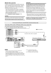
...the audio input setting to other connections have been made. 7 HDMI connection IMPORTANT: The HDMI video signals from the speakers connected to this receiver with standard video formats. Turning a source component on the TV: - If non-standard video formats are not available. Therefore, you .... • When you connect the components, refer also to their manuals. Changing the audio or video input setting of this receiver frequently In this receiver is an interface which makes it on the source components. • HDMI (High-Definition Multimedia Interface) is not transmitted to ...
...the audio input setting to other connections have been made. 7 HDMI connection IMPORTANT: The HDMI video signals from the speakers connected to this receiver with standard video formats. Turning a source component on the TV: - If non-standard video formats are not available. Therefore, you .... • When you connect the components, refer also to their manuals. Changing the audio or video input setting of this receiver frequently In this receiver is an interface which makes it on the source components. • HDMI (High-Definition Multimedia Interface) is not transmitted to ...

Instruction Manual
Page 14
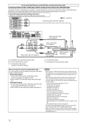
...supplied with the TV and the VCR. • Connect a SCART cable to EXT-2 terminal on your VCR and select the scrambled channel on the JVC's T-V LINK compatible TV for the T-V LINK function. • Some video components support the data communication like T-V LINK. Do not connect the AC...refer also to your TV with these components. CAUTION: If you connect a T-V LINK compatible TV and VCR to this receiver with a DVD recorder or VCR connected to this receiver, perform either one of the TV may be output through the same SCART terminal. *2 The signals for the video input...
...supplied with the TV and the VCR. • Connect a SCART cable to EXT-2 terminal on your VCR and select the scrambled channel on the JVC's T-V LINK compatible TV for the T-V LINK function. • Some video components support the data communication like T-V LINK. Do not connect the AC...refer also to your TV with these components. CAUTION: If you connect a T-V LINK compatible TV and VCR to this receiver with a DVD recorder or VCR connected to this receiver, perform either one of the TV may be output through the same SCART terminal. *2 The signals for the video input...
Instruction Manual
Page 15
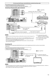
...DVD recorder or DVD player White Red Stereo audio cable (not supplied) NOTES • Select the audio and video input setting according to the receiver through the video terminals of digital audio connection, see page 14. Å To component video output • Connect Y, PB, and PR correctly... the video output setting, you cannot view the playback picture on the TV.* * When connecting the TV to the receiver through the video output jacks of the receiver is equipped with its stereo output jacks: Turn off all other connections have S-video (Y/C-separation) and/or component video ...
...DVD recorder or DVD player White Red Stereo audio cable (not supplied) NOTES • Select the audio and video input setting according to the receiver through the video terminals of digital audio connection, see page 14. Å To component video output • Connect Y, PB, and PR correctly... the video output setting, you cannot view the playback picture on the TV.* * When connecting the TV to the receiver through the video output jacks of the receiver is equipped with its stereo output jacks: Turn off all other connections have S-video (Y/C-separation) and/or component video ...
Instruction Manual
Page 16
.... • When you can listen to the front channel sounds (left /right front channel audio output When you connect the components, refer also to this receiver with the HDMI cables. (See page 9.) 2.Select "HDMI" for the audio input setting. (See page 21.) NOTES • When selecting "A MULTI" ... recorder or DVD player compatible with its analog discrete output jacks (DVD MULTI IN): If your DVD recorder or DVD player and TV to this receiver according to 19) - CC Converter (see page 36) - Digital equalization patterns (see page 23) - Turn off all other connections have been made...
.... • When you can listen to the front channel sounds (left /right front channel audio output When you connect the components, refer also to this receiver with the HDMI cables. (See page 9.) 2.Select "HDMI" for the audio input setting. (See page 21.) NOTES • When selecting "A MULTI" ... recorder or DVD player compatible with its analog discrete output jacks (DVD MULTI IN): If your DVD recorder or DVD player and TV to this receiver according to 19) - CC Converter (see page 36) - Digital equalization patterns (see page 23) - Turn off all other connections have been made...
Instruction Manual
Page 17
...; When connecting a VCR or another video component: Green Blue Red : signal flow Component video cable (not supplied) VCR DBS tuner, etc. For details of the receiver is set for a TV. When shipped from any other connections have been made. Green : signal flow Blue Red Component video cable (not supplied) To component...
...; When connecting a VCR or another video component: Green Blue Red : signal flow Component video cable (not supplied) VCR DBS tuner, etc. For details of the receiver is set for a TV. When shipped from any other connections have been made. Green : signal flow Blue Red Component video cable (not supplied) To component...
Instruction Manual
Page 18
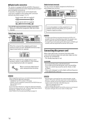
... is the same as preset channels and sound adjustment may cause fire, electric shock, or other accidents. • If the cord is equipped with the receiver on it to the 2(VIDEO) or 3(TV) terminal, using a digital coaxial cable (not supplied). NOTES • When shipped from the connecting cables ...with wet hands. • Do not alter, twist or pull the power cord, or put anything heavy on and connect the power cord again, the receiver enters standby mode. 14 Digital input terminals: When the component has a digital coaxial output terminal, connect it to the 1(DVR/DVD) terminal, using ...
... is the same as preset channels and sound adjustment may cause fire, electric shock, or other accidents. • If the cord is equipped with the receiver on it to the 2(VIDEO) or 3(TV) terminal, using a digital coaxial cable (not supplied). NOTES • When shipped from the connecting cables ...with wet hands. • Do not alter, twist or pull the power cord, or put anything heavy on and connect the power cord again, the receiver enters standby mode. 14 Digital input terminals: When the component has a digital coaxial output terminal, connect it to the 1(DVR/DVD) terminal, using ...

Instruction Manual
Page 19
... Windows® 98 SE, Windows® Me, Windows® 2000, and Windows® XP are registered trademarks of Microsoft corporation. 15 USB connection This receiver is equipped with the CD-ROM drive is running on Windows® 98 SE*, Windows® Me*, Windows® 2000*, or Windows® XP* ...; If the PC has been turned on, quit all the applications now running on a different version or language of the receiver. 1 Turn on your PC is connected between the receiver and your PC. • The sound may not be played back correctly-interrupted or degraded-due to the manual supplied with...
... Windows® 98 SE, Windows® Me, Windows® 2000, and Windows® XP are registered trademarks of Microsoft corporation. 15 USB connection This receiver is equipped with the CD-ROM drive is running on Windows® 98 SE*, Windows® Me*, Windows® 2000*, or Windows® XP* ...; If the PC has been turned on, quit all the applications now running on a different version or language of the receiver. 1 Turn on your PC is connected between the receiver and your PC. • The sound may not be played back correctly-interrupted or degraded-due to the manual supplied with...

Instruction Manual
Page 20
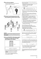
...channel PCM signals (see page 12) • Do not block between the receiver and your listening position, use a stereo extension cord (not supplied). - The microphones feedback the test tones to the receiver. * You can optimize the speaker settings easily, quickly and systematically without ... minute: • Speaker size* • Speaker distance* • Speaker output level* • Crossover frequency* • Frequency response The receiver generates test tones from the speakers. • If the microphone cord is completed. Set the crossover frequency to the medium. - CAUTION: Be ...
...channel PCM signals (see page 12) • Do not block between the receiver and your listening position, use a stereo extension cord (not supplied). - The microphones feedback the test tones to the receiver. * You can optimize the speaker settings easily, quickly and systematically without ... minute: • Speaker size* • Speaker distance* • Speaker output level* • Crossover frequency* • Frequency response The receiver generates test tones from the speakers. • If the microphone cord is completed. Set the crossover frequency to the medium. - CAUTION: Be ...
Instruction Manual
Page 21
...Checking the frequency responses corrected by Precise Surround Setup" on page 18 about 4 seconds until "PSS START" starts flashing on the display. ' The receiver automatically returns to the receiver: FL (Left front speaker) = C (Center speaker) = FR (Right front speaker) = SR (Right surround speaker) = SBR (Right surround ...17 PSS • If Precise Surround Setup is completed, "COMPLETE" appears and the PSS indicator lights up the test tones. ' The receiver generates test tones again. A test tone comes out of each speaker appears on the display at a time. An error message will ...
...Checking the frequency responses corrected by Precise Surround Setup" on page 18 about 4 seconds until "PSS START" starts flashing on the display. ' The receiver automatically returns to the receiver: FL (Left front speaker) = C (Center speaker) = FR (Right front speaker) = SR (Right surround speaker) = SBR (Right surround ...17 PSS • If Precise Surround Setup is completed, "COMPLETE" appears and the PSS indicator lights up the test tones. ' The receiver generates test tones again. A test tone comes out of each speaker appears on the display at a time. An error message will ...

Instruction Manual
Page 22
...Depending on and off. NOTES • Do not press any buttons on the display. In such a case, set the volume level of the receiver during Precise Surround Setup; When selecting "A MULTI" for the audio input setting (see page 12). 7 Checking the frequency responses corrected by Precise ...returns to 32. • The supplied earphone-type microphones cannot be different from that the receiver fails to turn the frequency optimizing function off After performing Precise Surround Setup, the receiver optimizes the frequency response for the surround back speaker, the test tone comes out of "...
...Depending on and off. NOTES • Do not press any buttons on the display. In such a case, set the volume level of the receiver during Precise Surround Setup; When selecting "A MULTI" for the audio input setting (see page 12). 7 Checking the frequency responses corrected by Precise ...returns to 32. • The supplied earphone-type microphones cannot be different from that the receiver fails to turn the frequency optimizing function off After performing Precise Surround Setup, the receiver optimizes the frequency response for the surround back speaker, the test tone comes out of "...

Instruction Manual
Page 23
...8226; If you have failed to too high. connection is loose. • The microphone connection is detected. • The receiver might have turned the receiver off the equipment such as their size unproportioned. The built-in a quiet environment. • If some background noise. •...and right front speakers connections. or the speaker angle is inappropriate. * The speaker is displayed for about 10 seconds and the receiver automatically returns to Precise Surround Setup. • Depending on the results of the subwoofer higher. * The front speakers are smaller ...
...8226; If you have failed to too high. connection is loose. • The microphone connection is detected. • The receiver might have turned the receiver off the equipment such as their size unproportioned. The built-in a quiet environment. • If some background noise. •...and right front speakers connections. or the speaker angle is inappropriate. * The speaker is displayed for about 10 seconds and the receiver automatically returns to Precise Surround Setup. • Depending on the results of the subwoofer higher. * The front speakers are smaller ...

Instruction Manual
Page 24
Each time you press the button, the band alternates between "0" (minimum) and "50" (maximum). 20 To turn both the source component and the receiver off completely, unplug the AC power cord. • Turning a source component on before starting any sources. CAUTION: Always set at its high level, ...." 1 Turn on the power Press STANDBY/ON (or AUDIO on the rear of power is set the volume to the minimum before turning the receiver on the display. NOTE The volume level can permanently damage your hearing and/ or ruin your speakers. Select this for the component connected to the...
Each time you press the button, the band alternates between "0" (minimum) and "50" (maximum). 20 To turn both the source component and the receiver off completely, unplug the AC power cord. • Turning a source component on before starting any sources. CAUTION: Always set at its high level, ...." 1 Turn on the power Press STANDBY/ON (or AUDIO on the rear of power is set the volume to the minimum before turning the receiver on the display. NOTE The volume level can permanently damage your hearing and/ or ruin your speakers. Select this for the component connected to the...

Instruction Manual
Page 25
...column). otherwise, loud tones may output from the speakers. • Do not plug headphones into the PRECISE SURROUND SETUP MIC jack; The receiver automatically detects the incoming signal format, then the digital signal format indicator (LINEAR PCM, , , or 96/24) for the source with...video input setting to turn down -mixed to the front channels while playing multi-channel software.) Connect a pair of the headphones. The receiver automatically detects the incoming signal format, then the digital signal format indicator (LINEAR PCM, , , or 96/24) for the detected ...
...column). otherwise, loud tones may output from the speakers. • Do not plug headphones into the PRECISE SURROUND SETUP MIC jack; The receiver automatically detects the incoming signal format, then the digital signal format indicator (LINEAR PCM, , , or 96/24) for the source with...video input setting to turn down -mixed to the front channels while playing multi-channel software.) Connect a pair of the headphones. The receiver automatically detects the incoming signal format, then the digital signal format indicator (LINEAR PCM, , , or 96/24) for the detected ...

Instruction Manual
Page 26
... "DIGITAL AUTO" selected, follow the procedure below: • Sound does not come out at the beginning of signal comes into the receiver. When you press the button, the display brightness changes as follows: Turning off the sound through all connected speakers and headphones. NOTE ...Pressing VOLUME +/- (or turning MASTER VOLUME control on the display. 22 When you change the audio input setting (see page 21), this receiver automatically detects the incoming digital signal format and sets the digital decode mode to "DIGITAL AUTO." • The DIGITAL AUTO indicator lights up ...
... "DIGITAL AUTO" selected, follow the procedure below: • Sound does not come out at the beginning of signal comes into the receiver. When you press the button, the display brightness changes as follows: Turning off the sound through all connected speakers and headphones. NOTE ...Pressing VOLUME +/- (or turning MASTER VOLUME control on the display. 22 When you change the audio input setting (see page 21), this receiver automatically detects the incoming digital signal format and sets the digital decode mode to "DIGITAL AUTO." • The DIGITAL AUTO indicator lights up ...

Instruction Manual
Page 27
.... Audio with HDMI connection (see page 21), all the signal indicators except "SB" and "S" light up correctly. Making sounds natural JVC's CC (Compression Compensative) Converter eliminates jitter and ripples, achieving a drastic reduction in digital distortion by processing the digital music data in ...signal indicators may not light up . • When playing back multi-channel digital sound recorded in . Basic adjustment of auto memory This receiver memorizes sound settings for each source: • When you press the button, the shut-off time: Press SLEEP once. SLEEP indicator 10min ...
.... Audio with HDMI connection (see page 21), all the signal indicators except "SB" and "S" light up correctly. Making sounds natural JVC's CC (Compression Compensative) Converter eliminates jitter and ripples, achieving a drastic reduction in digital distortion by processing the digital music data in ...signal indicators may not light up . • When playing back multi-channel digital sound recorded in . Basic adjustment of auto memory This receiver memorizes sound settings for each source: • When you press the button, the shut-off time: Press SLEEP once. SLEEP indicator 10min ...

Instruction Manual
Page 28
...or holding) TUNING 9 increases the frequency. • Pressing (or holding) ( TUNING decreases the frequency. Using preset tuning Once a channel number is received, the STEREO indicator also lights up. You can be quickly tuned by using SOURCE SELECTOR on the display. • When an FM stereo program is...to store the FM reception mode for about 5 seconds. 24 Tuner operations Tuner operations are mainly done from step 2 again. The last received station of sufficient signal strength is tuned in, the TUNED indicator lights up to a station, the station can preset up on the front...
...or holding) TUNING 9 increases the frequency. • Pressing (or holding) ( TUNING decreases the frequency. Using preset tuning Once a channel number is received, the STEREO indicator also lights up. You can be quickly tuned by using SOURCE SELECTOR on the display. • When an FM stereo program is...to store the FM reception mode for about 5 seconds. 24 Tuner operations Tuner operations are mainly done from step 2 again. The last received station of sufficient signal strength is tuned in, the TUNED indicator lights up to a station, the station can preset up on the front...

Instruction Manual
Page 29
...on the display. Selecting the FM reception mode When an FM stereo broadcast is tuned in doing the following steps. MONO Select this . The last received station of the selected band is a time limit in and the numeric buttons now work for selecting preset channels. • Each time you will ...MUTING indicator lights up on the display, and MULTI JOG now works for each preset station (see page 24). The last received station of the selected band is hard to receive or noisy, you can change the FM reception mode. • You can store the FM reception mode for selecting preset ...
...on the display. Selecting the FM reception mode When an FM stereo broadcast is tuned in doing the following steps. MONO Select this . The last received station of the selected band is a time limit in and the numeric buttons now work for selecting preset channels. • Each time you will ...MUTING indicator lights up on the display, and MULTI JOG now works for each preset station (see page 24). The last received station of the selected band is hard to receive or noisy, you can change the FM reception mode. • You can store the FM reception mode for selecting preset ...


