
Instructions
Page 4
Table of contents Introduction 2 Notes on handling 2 Supplied accessories 2 About discs 3 Playable disc types 3 Playable file types 4 Description of parts and controls 5 Connections 8 Connecting the FM and AM antennas 8 Connecting the satellite (front, center, surround) speakers ......9 Speaker layout 12 Connecting a TV 12 Connecting the powered ...
Table of contents Introduction 2 Notes on handling 2 Supplied accessories 2 About discs 3 Playable disc types 3 Playable file types 4 Description of parts and controls 5 Connections 8 Connecting the FM and AM antennas 8 Connecting the satellite (front, center, surround) speakers ......9 Speaker layout 12 Connecting a TV 12 Connecting the powered ...

Instructions
Page 5
... cleaning the system, use a soft cloth and follow the relevant instructions on the use of the system • There are no user-serviceable parts inside the system Turn the system off and disconnect the power cord plug from the wall outlet. Do not use any non-standard shape disc.../right) and center speakers (3) 10 m: For satellite speakers (surround left/right) (2) • Screws TH-C60: M5 x 40 mm (4) M4 x 20 mm (8) TH-C50: M5 x 40 mm (2) M4 x 20 mm (4) • Speaker cord clamps TH-C60 (4) TH-C50 (2) 2 If anything is level, dry and neither too hot nor too cold; Using the system...
... cleaning the system, use a soft cloth and follow the relevant instructions on the use of the system • There are no user-serviceable parts inside the system Turn the system off and disconnect the power cord plug from the wall outlet. Do not use any non-standard shape disc.../right) and center speakers (3) 10 m: For satellite speakers (surround left/right) (2) • Screws TH-C60: M5 x 40 mm (4) M4 x 20 mm (8) TH-C50: M5 x 40 mm (2) M4 x 20 mm (4) • Speaker cord clamps TH-C60 (4) TH-C50 (2) 2 If anything is level, dry and neither too hot nor too cold; Using the system...
Instructions
Page 8
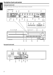
Description of parts and controls Front panel (center unit) The numbers in the figures indicate the pages where the details of the parts are described. Display window 21 24 36 37 20 24 18 12 18 20 20 20 37 36 30 28 31 31, 32 19 19 19 21, 36 17 Disc tray (inside): 19 Remote sensor: 7 17 Rear panel (center unit) 16 16 19 13 17 13 13 8 13 12 38 12 12 13 13 5
Description of parts and controls Front panel (center unit) The numbers in the figures indicate the pages where the details of the parts are described. Display window 21 24 36 37 20 24 18 12 18 20 20 20 37 36 30 28 31 31, 32 19 19 19 21, 36 17 Disc tray (inside): 19 Remote sensor: 7 17 Rear panel (center unit) 16 16 19 13 17 13 13 8 13 12 38 12 12 13 13 5

Instructions
Page 9
Power cord: 13 Rear 6 Description of parts and controls Powered subwoofer SP-PWC60/SP-PWC50 SP-PWC40 13 POWER ON 11 lamp: 16 Front Power cord: 13 Rear 13 11 POWER ON lamp: 16 Front NOTE • For safety reasons, always ensure that there is sufficient space behind the powered subwoofer. * Do not block the ventilation openings to allow proper air circulation by the cooling fan.
Power cord: 13 Rear 6 Description of parts and controls Powered subwoofer SP-PWC60/SP-PWC50 SP-PWC40 13 POWER ON 11 lamp: 16 Front Power cord: 13 Rear 13 11 POWER ON lamp: 16 Front NOTE • For safety reasons, always ensure that there is sufficient space behind the powered subwoofer. * Do not block the ventilation openings to allow proper air circulation by the cooling fan.

Instructions
Page 10
Description of parts and controls Remote control 17 19 Number buttons: 22 26 18 - 37 25 - 32 15, 21 19, 37 22, 36 28, 29 29 31 30, ...
Description of parts and controls Remote control 17 19 Number buttons: 22 26 18 - 37 25 - 32 15, 21 19, 37 22, 36 28, 29 29 31 30, ...

Instructions
Page 12
...). • Take care not to locate each speaker correctly. Connections Do not connect the power cord until all other connections have been made. For TH-C50 When assembling a speaker without stand: Speaker A: Use these screws (M4 x 45 mm) when assembling the speaker with the base plate, use... * When assembling the speaker with the base plate. For the surround speakers of each speaker from the label on the rear to drop any component part while assembling; otherwise, it may cause damage to the floor or injury. 1 Speaker Stand Screw M5 x 40 mm (supplied) 2 Front speaker Surround...
...). • Take care not to locate each speaker correctly. Connections Do not connect the power cord until all other connections have been made. For TH-C50 When assembling a speaker without stand: Speaker A: Use these screws (M4 x 45 mm) when assembling the speaker with the base plate, use... * When assembling the speaker with the base plate. For the surround speakers of each speaker from the label on the rear to drop any component part while assembling; otherwise, it may cause damage to the floor or injury. 1 Speaker Stand Screw M5 x 40 mm (supplied) 2 Front speaker Surround...

Instructions
Page 35
...appears on the TV screen. 2 Press Cursor 3/2 to highlight . 3 Press ENTER. 4 Press Cursor Y/5 repeatedly to select "A-B". 5 Press ENTER at the end of the part you watch DVD playback after connecting your TV. (See page 12.) Set the video output to repeat (point A). Tray lock You can adjust the balance... of a desired part by which you want to AUDIO. To set and the display automatically disappears a few seconds later. To cancel Carry out the same operation again....
...appears on the TV screen. 2 Press Cursor 3/2 to highlight . 3 Press ENTER. 4 Press Cursor Y/5 repeatedly to select "A-B". 5 Press ENTER at the end of the part you watch DVD playback after connecting your TV. (See page 12.) Set the video output to repeat (point A). Tray lock You can adjust the balance... of a desired part by which you want to AUDIO. To set and the display automatically disappears a few seconds later. To cancel Carry out the same operation again....

Instructions
Page 42
... connected. Check the connection. Connect the cord correctly. (See page 12.) Use a playable disc or file. (See pages 3 and 4.) No picture is divided into two parts. such as insecticides to it. - DO NOT wipe it for a long time. Replace the batteries. (See page 7.) Hide the remote sensor from direct sunlight. Select...
... connected. Check the connection. Connect the cord correctly. (See page 12.) Use a playable disc or file. (See pages 3 and 4.) No picture is divided into two parts. such as insecticides to it. - DO NOT wipe it for a long time. Replace the batteries. (See page 7.) Hide the remote sensor from direct sunlight. Select...


