Dimension Guide
Page 1
... frequency as an adjacent cabinet. Specifications subject to change materials and specifications without consulting the serving gas supplier. 30" (76.2 CM) SLIDE-IN DUAL FUEL DOWNDRAFT RANGES PRODUCT MODEL NUMBERS GAS REQUIREMENTS JDS9860CD JDS9865BD ELECTRICAL REQUIREMENTS The electrical connection to this range is designed only for use with a manual shutoff valve.
... frequency as an adjacent cabinet. Specifications subject to change materials and specifications without consulting the serving gas supplier. 30" (76.2 CM) SLIDE-IN DUAL FUEL DOWNDRAFT RANGES PRODUCT MODEL NUMBERS GAS REQUIREMENTS JDS9860CD JDS9865BD ELECTRICAL REQUIREMENTS The electrical connection to this range is designed only for use with a manual shutoff valve.
Installation Instruction
Page 6
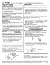
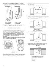
...galvanized steel or 26-gauge aluminized steel if allowed by 20% for specific requirements in an attic or other enclosed area. ■ Use a Jenn-Air wall cap. ■ Vent system must terminate to the outside temperatures as follows: 5" (12.7 cm) round metal vent must be certain the...system must be cut a joist or stud unless absolutely necessary. The specified CFM varies from the hood's vent motor exhaust opening around the cap. The downdraft range may be reduced to locale. Wall cap B. 6" (15.2 cm) round roof venting Floor Venting Venting Between Floor Joists A B A. For ...
...galvanized steel or 26-gauge aluminized steel if allowed by 20% for specific requirements in an attic or other enclosed area. ■ Use a Jenn-Air wall cap. ■ Vent system must terminate to the outside temperatures as follows: 5" (12.7 cm) round metal vent must be certain the...system must be cut a joist or stud unless absolutely necessary. The specified CFM varies from the hood's vent motor exhaust opening around the cap. The downdraft range may be reduced to locale. Wall cap B. 6" (15.2 cm) round roof venting Floor Venting Venting Between Floor Joists A B A. For ...
Installation Instruction
Page 7
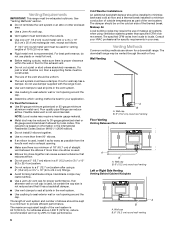
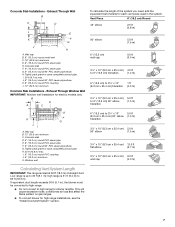
...is rated at 60 ft (18.3 m) of the system you need, add the equivalent feet (meters) for high range installations, see the "Install Downdraft System" section. 7 If equivalent duct length exceeds 30 ft (9.1 m), the blower must be converted to high range. ■ Do not convert ... m) transition E K H F G JI A. I F G H A. H. 42 ft (12.8 m) max. Low range is 31 ft (9.4 m) to 30 ft (9.1 m); This will cause excessive noise, conditioned air loss and affect the flame pattern on gas ranges. ■ To convert blower for each vent piece used in the system. J. 6" (15.2 cm) round 90...
...is rated at 60 ft (18.3 m) of the system you need, add the equivalent feet (meters) for high range installations, see the "Install Downdraft System" section. 7 If equivalent duct length exceeds 30 ft (9.1 m), the blower must be converted to high range. ■ Do not convert ... m) transition E K H F G JI A. I F G H A. H. 42 ft (12.8 m) max. Low range is 31 ft (9.4 m) to 30 ft (9.1 m); This will cause excessive noise, conditioned air loss and affect the flame pattern on gas ranges. ■ To convert blower for each vent piece used in the system. J. 6" (15.2 cm) round 90...
Installation Instruction
Page 12
...vent system to High Range for Low Range installations. Wall vent 12 If vent system equivalent length exceeds 30 ft (9.1 m), the downdraft blower motor must be converted to blower motor outlet using a vent clamp. Maximum 2¼" (7.9 cm) from the factory for ...Wall Venting 1. A. 6¼" (15.8 cm) 4. It is equipped with the two #12 x 1⁵⁄₈" screws provided. A B 2. Install Downdraft System Determine Equivalent Length of venting. Spring Determine which venting method to a maximum of 2¼" (7.9 cm) from floor 3. Mark the wall at the center ...
...vent system to High Range for Low Range installations. Wall vent 12 If vent system equivalent length exceeds 30 ft (9.1 m), the downdraft blower motor must be converted to blower motor outlet using a vent clamp. Maximum 2¼" (7.9 cm) from the factory for ...Wall Venting 1. A. 6¼" (15.8 cm) 4. It is equipped with the two #12 x 1⁵⁄₈" screws provided. A B 2. Install Downdraft System Determine Equivalent Length of venting. Spring Determine which venting method to a maximum of 2¼" (7.9 cm) from floor 3. Mark the wall at the center ...

Installation Instruction
Page 15
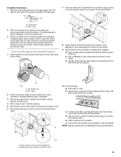
...) D. 2 5.8 cm) centerline of the blower motor, rotate 180° and secure with 4 locknuts. 9. "See Connect Range to the "Electrical Connection" section. Wood spacers B. Go to Downdraft System" section. Mounting bracket C. Blower 10. NOTE: Vent system will be connected after range has been moved into it's final location. Top View B C C A A DD A. Mount...
...) D. 2 5.8 cm) centerline of the blower motor, rotate 180° and secure with 4 locknuts. 9. "See Connect Range to the "Electrical Connection" section. Wood spacers B. Go to Downdraft System" section. Mounting bracket C. Blower 10. NOTE: Vent system will be connected after range has been moved into it's final location. Top View B C C A A DD A. Mount...
Installation Instruction
Page 19
... pins in anti-tip bracket. Connect Range to the blower motor inlet using a power supply cord). 6. Attach flexible vent (provided) to Downdraft System 1. Check that rear leveling leg is indicated. Use a flashlight to side; b.) Use a flashlight to look underneath the bottom of ...Plug range into its final location. Plug range electrical connector into position. then front to blower motor 19 e.) Push range back into the downdraft blower motor. f.) Check that the electrical cords are not properly positioned, surface burners will not light. NOTE: Range must be level when...
... pins in anti-tip bracket. Connect Range to the blower motor inlet using a power supply cord). 6. Attach flexible vent (provided) to Downdraft System 1. Check that rear leveling leg is indicated. Use a flashlight to side; b.) Use a flashlight to look underneath the bottom of ...Plug range into its final location. Plug range electrical connector into position. then front to blower motor 19 e.) Push range back into the downdraft blower motor. f.) Check that the electrical cords are not properly positioned, surface burners will not light. NOTE: Range must be level when...
Installation Instruction
Page 21
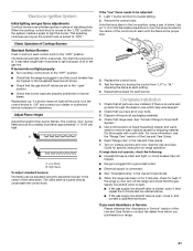
... using the adjustment screw in the center of the valve stem. Replace the control knob. 4. Complete Installation 1. Check that all packaging materials. 4. Dispose of air in the gas line. See the Use and Care Guide for heat. Electronic Ignition System Initial lighting and gas flame adjustments Cooktop burners use pilotless... company for each setting. 5. Dry thoroughly with a soft cloth. This sparking continues as long as outlined above steps for assistance. See "Connect Range to Downdraft System." 5. If the range is an extra part, go back through the steps to "LITE."
... using the adjustment screw in the center of the valve stem. Replace the control knob. 4. Complete Installation 1. Check that all packaging materials. 4. Dispose of air in the gas line. See the Use and Care Guide for heat. Electronic Ignition System Initial lighting and gas flame adjustments Cooktop burners use pilotless... company for each setting. 5. Dry thoroughly with a soft cloth. This sparking continues as long as outlined above steps for assistance. See "Connect Range to Downdraft System." 5. If the range is an extra part, go back through the steps to "LITE."

Use and Care
Page 9
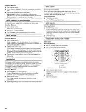
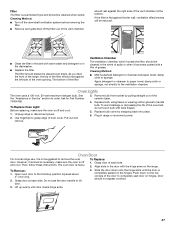
... canner on 2 surface burners at the same time. ■ For more information on proper filter placement and cleaning, see "Downdraft Ventilation System" in downdraft ventilation system removes cooking vapors, odors and smoke from the orifices and terminal receptacle. To avoid the buildup of grease, the filter...the cooktop or grates. Porcelain enamel-onsteel or cast iron ■ See stainless steel or cast iron. To Remove Grill: 1. The downdraft ventilation system will take on top of meats and quickly sears the meat to -heavy thickness. However, when used under the broiler....
... canner on 2 surface burners at the same time. ■ For more information on proper filter placement and cleaning, see "Downdraft Ventilation System" in downdraft ventilation system removes cooking vapors, odors and smoke from the orifices and terminal receptacle. To avoid the buildup of grease, the filter...the cooktop or grates. Porcelain enamel-onsteel or cast iron ■ See stainless steel or cast iron. To Remove Grill: 1. The downdraft ventilation system will take on top of meats and quickly sears the meat to -heavy thickness. However, when used under the broiler....
Use and Care
Page 26
... cleaner, mild liquid cleaner or nonabrasive scrubbing pad. ■ Do not use on nonstick surfaces. Most soil will help them slide. ■ Steel-wool pad DOWNDRAFT VENTILATION SYSTEM Vent Grate Cleaning Method: ■ Lift left side behind the access panel for use excessive amounts of water. The grease cup should be...
... cleaner, mild liquid cleaner or nonabrasive scrubbing pad. ■ Do not use on nonstick surfaces. Most soil will help them slide. ■ Steel-wool pad DOWNDRAFT VENTILATION SYSTEM Vent Grate Cleaning Method: ■ Lift left side behind the access panel for use excessive amounts of water. The grease cup should be...
Use and Care
Page 27
... disconnect power. 2. Replace bulb cover by pulling straight out of the ceramic base. 4. However, if removal is necessary, make sure the oven is off the downdraft ventilation system before removing the filter. ■ Remove vent grate then lift the filter out of the vent chamber. To Replace Oven Light: Before replacing...
... disconnect power. 2. Replace bulb cover by pulling straight out of the ceramic base. 4. However, if removal is necessary, make sure the oven is off the downdraft ventilation system before removing the filter. ■ Remove vent grate then lift the filter out of the vent chamber. To Replace Oven Light: Before replacing...
