Dimension Guide
Page 1
...8328;" (1.0 cm) dimension. Place level on the model/serial rating plate. **If connecting to a 50-amp circuit, use a 50-amp rated cord with LP gas. Range Rating* 120/240 Volts 8.8 - 16.5 KW 16.6 - 22.5 KW 120/208 Volts 7.8 - 12.5 KW 12.6 - 18.5 KW Specified Rating of ³&#...8260;₄" (1.9 cm) rigid pipe to shutoff valve. Natural gas: This range is design-certified by a qualified electrician. No attempt shall be level. NOTE: Pipe-joint compounds that can be located in insufficient gas supply. All strains...
...8328;" (1.0 cm) dimension. Place level on the model/serial rating plate. **If connecting to a 50-amp circuit, use a 50-amp rated cord with LP gas. Range Rating* 120/240 Volts 8.8 - 16.5 KW 16.6 - 22.5 KW 120/208 Volts 7.8 - 12.5 KW 12.6 - 18.5 KW Specified Rating of ³&#...8260;₄" (1.9 cm) rigid pipe to shutoff valve. Natural gas: This range is design-certified by a qualified electrician. No attempt shall be level. NOTE: Pipe-joint compounds that can be located in insufficient gas supply. All strains...
Dimension Guide
Page 2
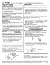
...located behind the storage drawer on the left-hand side of the oven frame) F. 29" (73.7 cm) from handle to back of range** G. 27" (68.6 cm) from handle to change without notice. Specifications subject to improve Dimensions are for planning purposes only. NOTE: ...complete details, see NOTE. G F B C D E A B C H D E I I . 3" (7.6 cm) min. Gas information plate (located on the right-hand side of range** F. 29⁷⁄₈" (75.9 cm)* C. Model JDS9865 NOTE: Cooktop shown may be installed with 25" (63.5 cm) countertop; D. 23¹⁄₄ " (59.1 ...
...located behind the storage drawer on the left-hand side of the oven frame) F. 29" (73.7 cm) from handle to back of range** G. 27" (68.6 cm) from handle to change without notice. Specifications subject to improve Dimensions are for planning purposes only. NOTE: ...complete details, see NOTE. G F B C D E A B C H D E I I . 3" (7.6 cm) min. Gas information plate (located on the right-hand side of range** F. 29⁷⁄₈" (75.9 cm)* C. Model JDS9865 NOTE: Cooktop shown may be installed with 25" (63.5 cm) countertop; D. 23¹⁄₄ " (59.1 ...
Installation Instruction
Page 2
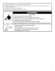
Always read and obey all safety messages. IMPORTANT: Do not install a ventilation system that blows air downward toward this manual is detected, follow the safety alert symbol and either the word "DANGER" or "WARNING." RANGE SAFETY Your safety and the safety of others . This is , tell you how to do if you don...
Always read and obey all safety messages. IMPORTANT: Do not install a ventilation system that blows air downward toward this manual is detected, follow the safety alert symbol and either the word "DANGER" or "WARNING." RANGE SAFETY Your safety and the safety of others . This is , tell you how to do if you don...
Installation Instruction
Page 3
...of Massachusetts. ■ If using a ball valve, it shall be killed. Re-engage anti-tip bracket if range is engaged in death or serious burns to follow these instructions can tip the range and be a T-handle type. ■ A flexible gas connector, when used, must be performed by a ...tip bracket installed and engaged. Install anti-tip bracket to floor or wall. • Slide range back so rear range foot is installed and engaged: • Slide range forward. • Look for details. 3 Range Foot Anti-Tip Bracket To verify the anti-tip bracket is under anti-tip bracket. •...
...of Massachusetts. ■ If using a ball valve, it shall be killed. Re-engage anti-tip bracket if range is engaged in death or serious burns to follow these instructions can tip the range and be a T-handle type. ■ A flexible gas connector, when used, must be performed by a ...tip bracket installed and engaged. Install anti-tip bracket to floor or wall. • Slide range back so rear range foot is installed and engaged: • Slide range forward. • Look for details. 3 Range Foot Anti-Tip Bracket To verify the anti-tip bracket is under anti-tip bracket. •...
Installation Instruction
Page 4
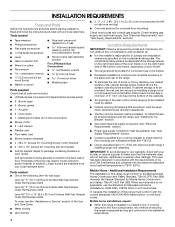
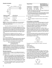
Tools needed ■ One of the following Jenn-Air wall caps: Jenn-Air® 5" (12.7 cm) Round Surface Wall Cap Damper Order Part Number A405 Jenn-Air® 6" (15.2 cm) Round Surface Wall Cap Damper Order Part Number A406 Jenn-Air® 3¼" x 10" (8.3 x 25.4 cm) Surface Wall Cap Damper Order Part ...Number A403 To order, see "Install Anti-Tip Bracket" section. ■ Grounded electrical supply is to the back wall or floor. Thickness of securing the range is the installer's ...
Tools needed ■ One of the following Jenn-Air wall caps: Jenn-Air® 5" (12.7 cm) Round Surface Wall Cap Damper Order Part Number A405 Jenn-Air® 6" (15.2 cm) Round Surface Wall Cap Damper Order Part Number A406 Jenn-Air® 3¼" x 10" (8.3 x 25.4 cm) Surface Wall Cap Damper Order Part ...Number A403 To order, see "Install Anti-Tip Bracket" section. ■ Grounded electrical supply is to the back wall or floor. Thickness of securing the range is the installer's ...
Installation Instruction
Page 5
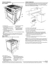
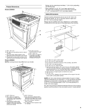
... the rear and on the right-hand side of oven door protrudes 5" (12.7 cm) beyond 24" (61.0 cm) base cabinet. clearance from back wall or range will not slide all the way back. A G B C F D G A. 13" (33.0 cm) upper cabinet depth B. 30" (76.2 cm) min. Nothing located in *... Model JDS9865 NOTE: Cooktop shown may be flush mounted. Product Dimensions Model JDS9860 G F A B E *Range can extend more than No. 28 MSG sheet steel, 0.015" (0.4 mm) stainless steel, 0.024" (0.6 mm) aluminum or 0.020" (0.5 mm) copper. 30" (76.2 cm) ...
... the rear and on the right-hand side of oven door protrudes 5" (12.7 cm) beyond 24" (61.0 cm) base cabinet. clearance from back wall or range will not slide all the way back. A G B C F D G A. 13" (33.0 cm) upper cabinet depth B. 30" (76.2 cm) min. Nothing located in *... Model JDS9865 NOTE: Cooktop shown may be flush mounted. Product Dimensions Model JDS9860 G F A B E *Range can extend more than No. 28 MSG sheet steel, 0.015" (0.4 mm) stainless steel, 0.024" (0.6 mm) aluminum or 0.020" (0.5 mm) copper. 30" (76.2 cm) ...
Installation Instruction
Page 6
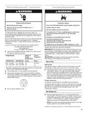
... should be used . ■ Elbows too close together can reduce airflow. The downdraft range may require the use a 5" (12.7 cm) elbow in an attic or other enclosed area. ■ Use a Jenn-Air wall cap. ■ Vent system must terminate to provide efficient performance. The length of... vent system and number of elbows should be certain the cap size is recommended. Venting Requirements IMPORTANT: This range must be cut a joist or stud...
... should be used . ■ Elbows too close together can reduce airflow. The downdraft range may require the use a 5" (12.7 cm) elbow in an attic or other enclosed area. ■ Use a Jenn-Air wall cap. ■ Vent system must terminate to provide efficient performance. The length of... vent system and number of elbows should be certain the cap size is recommended. Venting Requirements IMPORTANT: This range must be cut a joist or stud...
Installation Instruction
Page 7
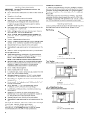
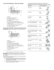
...If equivalent duct length exceeds 30 ft (9.1 m), the blower must be converted to high range. ■ Do not convert to 30 ft (9.1 m); This will cause excessive noise, conditioned air loss and affect the flame pattern on gas ranges. ■ To convert blower for electric models only. Exhaust Through Wall B A ...Installations - Exhaust Through Window Well IMPORTANT: Window well installation for high range installations, see the "Install Downdraft System" section. 7 H. 42 ft (12.8 m) max. high range is up to high range for each vent piece used in the system. Concrete slab D. 6"...
...If equivalent duct length exceeds 30 ft (9.1 m), the blower must be converted to high range. ■ Do not convert to 30 ft (9.1 m); This will cause excessive noise, conditioned air loss and affect the flame pattern on gas ranges. ■ To convert blower for electric models only. Exhaust Through Wall B A ...Installations - Exhaust Through Window Well IMPORTANT: Window well installation for high range installations, see the "Install Downdraft System" section. 7 H. 42 ft (12.8 m) max. high range is up to high range for each vent piece used in the system. Concrete slab D. 6"...
Installation Instruction
Page 8
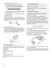
...cord should be used . Do not use kits that greatly reduce performance. For a 3-wire connection order UL listed power cord Part Number 74011285. 8 Range Rating* Specified Rating of NEMA Type 14-50R is properly grounded. See "Electrical Connection" section. When a 4-wire receptacle of Power Supply Cord Kit...in doubt as specified on the right-hand side of a UL listed, 3-wire, 250-volt, 40- Flexible vent creates back pressure and air turbulence that specify use of the bottom oven frame, depending on the supply end. mobile homes; Cord should be used , a matching ...
...cord should be used . Do not use kits that greatly reduce performance. For a 3-wire connection order UL listed power cord Part Number 74011285. 8 Range Rating* Specified Rating of NEMA Type 14-50R is properly grounded. See "Electrical Connection" section. When a 4-wire receptacle of Power Supply Cord Kit...in doubt as specified on the right-hand side of a UL listed, 3-wire, 250-volt, 40- Flexible vent creates back pressure and air turbulence that specify use of the bottom oven frame, depending on the supply end. mobile homes; Cord should be used , a matching ...
Installation Instruction
Page 9
... and ordinances. IMPORTANT: This installation must conform with all gas connections. No attempt shall be ½" (1.3 cm) minimum. Range Rating* Rating of a qualified person include: licensed heating personnel, authorized gas company personnel, and authorized service personnel. Canada Only WARNING... Gas Supply Requirements WARNING Electrical Shock Hazard Electrically ground range. With LP gas, piping or tubing size can be made to do so can be plugged into a standard 14-50R...
... and ordinances. IMPORTANT: This installation must conform with all gas connections. No attempt shall be ½" (1.3 cm) minimum. Range Rating* Rating of a qualified person include: licensed heating personnel, authorized gas company personnel, and authorized service personnel. Canada Only WARNING... Gas Supply Requirements WARNING Electrical Shock Hazard Electrically ground range. With LP gas, piping or tubing size can be made to do so can be plugged into a standard 14-50R...
Installation Instruction
Page 10
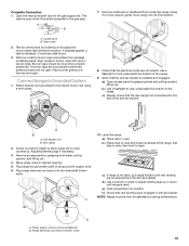
...or less than 30" (76.2 cm), adjust the ³⁄₈" (1.0 cm) dimension. This valve should be equipped with the range connection. Range must be as an adjacent cabinet. The valve is required. Gas supply line B. Rigid pipe connection: The rigid pipe connection requires a ... square finish (flat) countertop and the opening . Formed front-edged countertops must be level. All strains must be used for connecting range to the range opening width is needed for proper operation: Natural gas: Minimum pressure: 5" WCP Maximum pressure: 14" WCP LP gas: Minimum pressure:...
...or less than 30" (76.2 cm), adjust the ³⁄₈" (1.0 cm) dimension. This valve should be equipped with the range connection. Range must be as an adjacent cabinet. The valve is required. Gas supply line B. Rigid pipe connection: The rigid pipe connection requires a ... square finish (flat) countertop and the opening . Formed front-edged countertops must be level. All strains must be used for connecting range to the range opening width is needed for proper operation: Natural gas: Minimum pressure: 5" WCP Maximum pressure: 14" WCP LP gas: Minimum pressure:...
Installation Instruction
Page 11
... is necessary, use a wrench or pliers to loosen the leveling legs. 7. Using 2 or more people, stand range back up onto cardboard or hardboard. When the range is taped to support the range when it on its back. 4. Place cardboard or hardboard in cutout so that there is needed to floor or... instructions. Tip Over Hazard A child or adult can use : floor or wall. If you have a stone or masonry floor, you can tip the range and be loosened to add up into its final location, check that is at the correct height, check that right (or left side or right...
... is necessary, use a wrench or pliers to loosen the leveling legs. 7. Using 2 or more people, stand range back up onto cardboard or hardboard. When the range is taped to support the range when it on its back. 4. Place cardboard or hardboard in cutout so that there is needed to floor or... instructions. Tip Over Hazard A child or adult can use : floor or wall. If you have a stone or masonry floor, you can tip the range and be loosened to add up into its final location, check that is at the correct height, check that right (or left side or right...
Installation Instruction
Page 12
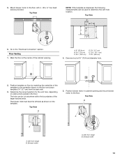
... the blower inlet by pressing one of the cabinet opening . Mark a vertical line up to the wall or floor with a dual range blower. Anti-tip bracket 5. If vent system equivalent length exceeds 30 ft (9.1 m), the downdraft blower motor must be converted to the...A. 18¾" (47.6 cm) maximum from the factory for obstructions before marking the vent hole location. Position blower motor in cabinet opening . Check for Low Range installations. See "Calculating Vent System Length" section. Anti-tip bracket A. #12 x 1⁵⁄₈" screws B. It is equipped with the two #12 ...
... the blower inlet by pressing one of the cabinet opening . Mark a vertical line up to the wall or floor with a dual range blower. Anti-tip bracket 5. If vent system equivalent length exceeds 30 ft (9.1 m), the downdraft blower motor must be converted to the...A. 18¾" (47.6 cm) maximum from the factory for obstructions before marking the vent hole location. Position blower motor in cabinet opening . Check for Low Range installations. See "Calculating Vent System Length" section. Anti-tip bracket A. #12 x 1⁵⁄₈" screws B. It is equipped with the two #12 ...
Installation Instruction
Page 13
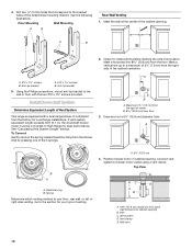
...face the left side as shown on the floor and place template 2¼" (5.7 cm) from the back wall. 3. Inlet from range B. Mount blower motor to the "Electrical Connection" section. Top View NOTE: If the template is misplaced, the following measurements can be used...9" (22.8 cm) B. 3¹⁄₈" (7.9 cm) C. 6³⁄₈" (16.2 cm) D. 2¼" (5.7 cm) E. 12½" (31.7 cm) F. 3½" (8.9 cm) 4. Inlet from range B. Mark the floor at the center of the template to the floor. 5. Go to the floor with 4 - #8 x ¾" hex head screws provided. Exhaust outlet 13...
...face the left side as shown on the floor and place template 2¼" (5.7 cm) from the back wall. 3. Inlet from range B. Mount blower motor to the "Electrical Connection" section. Top View NOTE: If the template is misplaced, the following measurements can be used...9" (22.8 cm) B. 3¹⁄₈" (7.9 cm) C. 6³⁄₈" (16.2 cm) D. 2¼" (5.7 cm) E. 12½" (31.7 cm) F. 3½" (8.9 cm) 4. Inlet from range B. Mark the floor at the center of the template to the floor. 5. Go to the floor with 4 - #8 x ¾" hex head screws provided. Exhaust outlet 13...

Installation Instruction
Page 15
...back wall to edge of wood spacer C. 8¾" (22.2 cm) D. 2 5.8 cm) centerline of the blower motor, rotate 180° and secure with 4 locknuts. 9. "See Connect Range to the floor. Position 2 wood spacers and mount them to Downdraft System" section. A. 2" x 4" (5.0 x 10.2 cm) wood spacers B. 2⁷⁄₈" (7.3 cm) from the... Top View B C C A A DD A. Mount blower motor to wood spacers using 4 - #8 x ¾" hex head screws provided. NOTE: Vent system will be connected after range has been moved into it's final location. Mounting bracket C. Blower 10. 7.
...back wall to edge of wood spacer C. 8¾" (22.2 cm) D. 2 5.8 cm) centerline of the blower motor, rotate 180° and secure with 4 locknuts. 9. "See Connect Range to the floor. Position 2 wood spacers and mount them to Downdraft System" section. A. 2" x 4" (5.0 x 10.2 cm) wood spacers B. 2⁷⁄₈" (7.3 cm) from the... Top View B C C A A DD A. Mount blower motor to wood spacers using 4 - #8 x ¾" hex head screws provided. NOTE: Vent system will be connected after range has been moved into it's final location. Mounting bracket C. Blower 10. 7.
Installation Instruction
Page 16
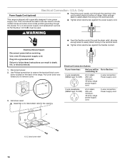
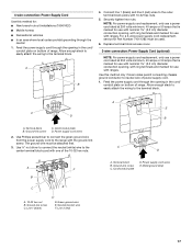
.... WARNING Electrical Shock Hazard Disconnect power before servicing. Disconnect power. 2. Electrical Connection Options If your home has: And you to the terminal block. This range is shipped with a specially designed 4-wire power supply cord. Use a new 40 amp power supply cord. Failure to : 4-wire receptacle (NEMA type 14...-50R) A UL listed, 250-volt minimum, 40-amp, range power supply cord 4-wire connection: Power supply cord 3-wire receptacle (NEMA type 10-50R) A UL listed, 250-volt minimum, 40-amp...
.... WARNING Electrical Shock Hazard Disconnect power before servicing. Disconnect power. 2. Electrical Connection Options If your home has: And you to the terminal block. This range is shipped with a specially designed 4-wire power supply cord. Use a new 40 amp power supply cord. Failure to : 4-wire receptacle (NEMA type 14...-50R) A UL listed, 250-volt minimum, 40-amp, range power supply cord 4-wire connection: Power supply cord 3-wire receptacle (NEMA type 10-50R) A UL listed, 250-volt minimum, 40-amp...
Installation Instruction
Page 17
... hex nut B. Line 1 (black) D D. Terminal block B. Allow enough slack to easily attach the wiring to the center terminal block post with one of range. Cord/conduit plate D. Ground-link screw C. Power supply cord wires E. The ground wire must be attached first. 3. Neutral (center) wire F. Feed the power...to the terminal block. Feed the power supply cord through the neutral 1. Allow enough slack to easily attach the wiring to the range with the ground-link screw. Use this method for: ■ New branch-circuit installations (1996 NEC) ■ Mobile homes &#...
... hex nut B. Line 1 (black) D D. Terminal block B. Allow enough slack to easily attach the wiring to the center terminal block post with one of range. Cord/conduit plate D. Ground-link screw C. Power supply cord wires E. The ground wire must be attached first. 3. Neutral (center) wire F. Feed the power...to the terminal block. Feed the power supply cord through the neutral 1. Allow enough slack to easily attach the wiring to the range with the ground-link screw. Use this method for: ■ New branch-circuit installations (1996 NEC) ■ Mobile homes &#...
Installation Instruction
Page 19
...is open when the handle is level. A B 7. Remove cardboard or hardboard from package containing parts. Using 2 or more people, gently move range into position. Open valve 2. If bubbles appear, a leak is removed from the anti-tip bracket. Correct any leak found. 3. Align recess ...in burner caps with pins in the gas supply line. If burner caps are not kinked. Connect Range to clear countertop. Check that the rear range foot is inserted into the downdraft blower motor. Use a flashlight to look underneath the bottom of the anti-tip bracket. 1...
...is open when the handle is level. A B 7. Remove cardboard or hardboard from package containing parts. Using 2 or more people, gently move range into position. Open valve 2. If bubbles appear, a leak is removed from the anti-tip bracket. Correct any leak found. 3. Align recess ...in burner caps with pins in the gas supply line. If burner caps are not kinked. Connect Range to clear countertop. Check that the rear range foot is inserted into the downdraft blower motor. Use a flashlight to look underneath the bottom of the anti-tip bracket. 1...
Installation Instruction
Page 21
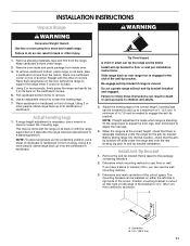
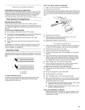
... Height Adjust the height of air in and turn to lowest setting. 2. Light 1 burner and turn each setting. 5. Replace the control knob. 4. Check that all packaging materials. 4. Check that burner caps are properly positioned on surface burners and oven. See "Connect Range to light because of top burner...test as the control knob is plugged in and the circuit breaker has not tripped or the household fuse has not blown. ■ Check that range level. A B A. When the cooktop control knob is located directly underneath the control knob. Use an ¹⁄₈" (3.0 mm) flat...
... Height Adjust the height of air in and turn to lowest setting. 2. Light 1 burner and turn each setting. 5. Replace the control knob. 4. Check that all packaging materials. 4. Check that burner caps are properly positioned on surface burners and oven. See "Connect Range to light because of top burner...test as the control knob is plugged in and the circuit breaker has not tripped or the household fuse has not blown. ■ Check that range level. A B A. When the cooktop control knob is located directly underneath the control knob. Use an ¹⁄₈" (3.0 mm) flat...

Installation Instruction
Page 22
...authorized gas company personnel, and authorized service personnel. Slide range back so rear range foot is moved. Gas pressure regulator IMPORTANT: Do not remove the gas pressure regulator. 22 To range B. Gas supply line 2. Unplug range or disconnect power. To Convert Gas Pressure Regulator 1. ... Hazard Use a new CSA International approved gas supply line. Install anti-tip bracket to children and adults. 1. Do not operate range without anti-tip bracket installed and engaged. Securely tighten all gas connections. Remove access panel by a qualified installer. Shutoff valve (...
...authorized gas company personnel, and authorized service personnel. Slide range back so rear range foot is moved. Gas pressure regulator IMPORTANT: Do not remove the gas pressure regulator. 22 To range B. Gas supply line 2. Unplug range or disconnect power. To Convert Gas Pressure Regulator 1. ... Hazard Use a new CSA International approved gas supply line. Install anti-tip bracket to children and adults. 1. Do not operate range without anti-tip bracket installed and engaged. Securely tighten all gas connections. Remove access panel by a qualified installer. Shutoff valve (...


