Dimension Guide
Page 1
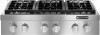
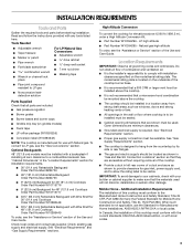
...that they are accessible without consulting the serving gas supplier. Additional Installation Requirements The installation of this cooktop must conform to improve Dimensions are shown must be visible. Model/serial rating plate (located on the...REQUIREMENTS IMPORTANT: Observe all governing codes and ordinances. The model/serial rating plate is also recommended. q The cooktop should be provided. q Grounded electrical supply is not applicable, use the Standard for planning purposes only. See... gas without requiring removal of combustion and ventilation air. Ref.
...that they are accessible without consulting the serving gas supplier. Additional Installation Requirements The installation of this cooktop must conform to improve Dimensions are shown must be visible. Model/serial rating plate (located on the...REQUIREMENTS IMPORTANT: Observe all governing codes and ordinances. The model/serial rating plate is also recommended. q The cooktop should be provided. q Grounded electrical supply is not applicable, use the Standard for planning purposes only. See... gas without requiring removal of combustion and ventilation air. Ref.
Dimension Guide
Page 2
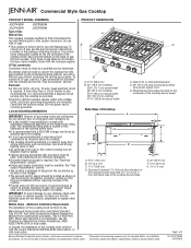
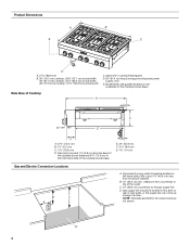
... depth I K D E C G H A** L B min.* M A. C. D. F. 18" (45.7 cm) min. Instructions packed with product. Commercial Style Gas Cooktop CABINET REQUIREMENTS Gas and Electric Connection Locations B C A A. NOTE: Solid side and bottom of cabinet cutout to gas opening cutout H. 6⁷⁄₈" (16.1 cm... (5.1 cm) cabinet side to the side wall or other combustible material above the cooktop Isfuirnfsa*tc*aeN6ll".iOn(1Tg5E.a2: Ircfambna)gcisekrwheaqoluol iidrsedcaobfnoosrvt4eru8ct"ht(ee1d2c1oo.f9oakcctmoo)pmc,bofuooskllttoiobwplestmhaneadteracrinoagol ...
... depth I K D E C G H A** L B min.* M A. C. D. F. 18" (45.7 cm) min. Instructions packed with product. Commercial Style Gas Cooktop CABINET REQUIREMENTS Gas and Electric Connection Locations B C A A. NOTE: Solid side and bottom of cabinet cutout to gas opening cutout H. 6⁷⁄₈" (16.1 cm... (5.1 cm) cabinet side to the side wall or other combustible material above the cooktop Isfuirnfsa*tc*aeN6ll".iOn(1Tg5E.a2: Ircfambna)gcisekrwheaqoluol iidrsedcaobfnoosrvt4eru8ct"ht(ee1d2c1oo.f9oakcctmoo)pmc,bofuooskllttoiobwplestmhaneadteracrinoagol ...
Installation Instruction
Page 2
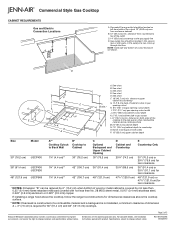
.... - For more information, contact your gas supplier from a neighbor's phone. If a gas leak is , tell you how to potential hazards that you don't follow instructions. COOKTOP SAFETY Your safety and the safety of others .
.... - For more information, contact your gas supplier from a neighbor's phone. If a gas leak is , tell you how to potential hazards that you don't follow instructions. COOKTOP SAFETY Your safety and the safety of others .
Installation Instruction
Page 3
... bases and burner caps ■ Griddle drip tray (on the underside of combustion and ventilation air. ■ It is required. Mobile Home - LP high altitude ■ Part Number W10394295 - See "Gas Supply Requirements" section. ■ The cooktop is designed to make sure that the materials used . Additional Installation Requirements The installation of...
... bases and burner caps ■ Griddle drip tray (on the underside of combustion and ventilation air. ■ It is required. Mobile Home - LP high altitude ■ Part Number W10394295 - See "Gas Supply Requirements" section. ■ The cooktop is designed to make sure that the materials used . Additional Installation Requirements The installation of...
Installation Instruction
Page 4
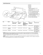
...enclosure sidewall B. 10" (25.4 cm) min. D E. 22" (55.9 cm) F. 3 8.4 cm) G 1.4 cm) Gas and Electric Connection Locations B C A A. D 4 from the back of Cooktop A B C G E F A. 27¾" (70.5 cm) B. 1¼" (3.2 cm) C. 7 18.8 cm) D. NOTE: Solid side and bottom of the outlet C. 14" (35.6 cm) ... A. 27¹⁄₈" (68.9 cm) B. 30" (76.2 cm) cooktop: 29⁷⁄₈" (75.1 cm) actual width 36" (91.4 cm) cooktop: 35⁷⁄₈" (90.4 cm) actual width 48" (121.9 cm) cooktop: 47⁷⁄₈" (120.8 cm) actual width C. Model/serial rating plate...
...enclosure sidewall B. 10" (25.4 cm) min. D E. 22" (55.9 cm) F. 3 8.4 cm) G 1.4 cm) Gas and Electric Connection Locations B C A A. D 4 from the back of Cooktop A B C G E F A. 27¾" (70.5 cm) B. 1¼" (3.2 cm) C. 7 18.8 cm) D. NOTE: Solid side and bottom of the outlet C. 14" (35.6 cm) ... A. 27¹⁄₈" (68.9 cm) B. 30" (76.2 cm) cooktop: 29⁷⁄₈" (75.1 cm) actual width 36" (91.4 cm) cooktop: 35⁷⁄₈" (90.4 cm) actual width 48" (121.9 cm) cooktop: 47⁷⁄₈" (120.8 cm) actual width C. Model/serial rating plate...
Installation Instruction
Page 5
... cm) for 36" (91.4 cm) and 48" (121.9 cm) cooktops. 5 See chart. See chart. clearance upper cabinet to countertop G 1.9 cm) back of the cooktop to the side wall or other combustible material above the cooktop surface. **NOTE: If backwall is constructed of a combustible material and a backguard... Dimension "B" can be equal on both sides P. 13" (33.0 cm) upper cabinet depth Size Model 30" (76.2 cm) JGCP430 A** Cooktop Cutout to Back Wall B* Cooktop to gas cutout L. 6" (15.2 cm) min. C. See chart. See chart. distance on both sides of cabinet cutout to gas opening cutout...
... cm) for 36" (91.4 cm) and 48" (121.9 cm) cooktops. 5 See chart. See chart. clearance upper cabinet to countertop G 1.9 cm) back of the cooktop to the side wall or other combustible material above the cooktop surface. **NOTE: If backwall is constructed of a combustible material and a backguard... Dimension "B" can be equal on both sides P. 13" (33.0 cm) upper cabinet depth Size Model 30" (76.2 cm) JGCP430 A** Cooktop Cutout to Back Wall B* Cooktop to gas cutout L. 6" (15.2 cm) min. C. See chart. See chart. distance on both sides of cabinet cutout to gas opening cutout...
Installation Instruction
Page 6
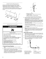
...piping or tubing size can result in the package containing literature. NOTE: Pipe-joint compounds that a separate circuit serving only this cooktop. Electrical Requirements WARNING Gas Supply Requirements WARNING Electrical Shock Hazard Plug into an outlet that the ground path is also recommended. ...limits, but proper grounding and polarity are located inside the control console and in insufficient gas supply. In the absence of the cooktop must be ½" (1.3 cm) minimum. IMPORTANT: This installation must conform with Natural gas. IMPORTANT: Leak testing of local ...
...piping or tubing size can result in the package containing literature. NOTE: Pipe-joint compounds that a separate circuit serving only this cooktop. Electrical Requirements WARNING Gas Supply Requirements WARNING Electrical Shock Hazard Plug into an outlet that the ground path is also recommended. ...limits, but proper grounding and polarity are located inside the control console and in insufficient gas supply. In the absence of the cooktop must be ½" (1.3 cm) minimum. IMPORTANT: This installation must conform with Natural gas. IMPORTANT: Leak testing of local ...
Installation Instruction
Page 7
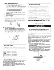
...that allows ease of opening and closing its individual shutoff valve must be isolated from literature packing. A B C A. Foam strip C. Cooktop 4. This valve should be located in excess of the gas supply piping system at test pressures equal to the countertop surface. The inlet...The valve is installed in line. ■ Must include a shutoff valve: The supply line must be equipped with this cooktop must be level with your cooktop. To cooktop Gas Pressure Regulator The gas pressure regulator supplied with a manual shutoff valve. Altitude Input ratings shown on a covered surface....
...that allows ease of opening and closing its individual shutoff valve must be isolated from literature packing. A B C A. Foam strip C. Cooktop 4. This valve should be located in excess of the gas supply piping system at test pressures equal to the countertop surface. The inlet...The valve is installed in line. ■ Must include a shutoff valve: The supply line must be equipped with this cooktop must be level with your cooktop. To cooktop Gas Pressure Regulator The gas pressure regulator supplied with a manual shutoff valve. Altitude Input ratings shown on a covered surface....
Installation Instruction
Page 8
...to avoid scratching the countertop. Must have ¹⁄₂" male pipe thread D. Check that the front edge of the cooktop is not kinked. C. Examples of the cooktop burner base and in a position where you can result in the "Location Requirements" section for information on its side or...If repositioning is a typical connection. Do not use with LP gas to the smaller thread ends of pipe fittings must be used to connect the cooktop to the existing gas line. Gas pressure regulator B. Use pipe-joint compound. Install Optional Backguard 36" (91.4 cm) and 48" (121.9...
...to avoid scratching the countertop. Must have ¹⁄₂" male pipe thread D. Check that the front edge of the cooktop is not kinked. C. Examples of the cooktop burner base and in a position where you can result in the "Location Requirements" section for information on its side or...If repositioning is a typical connection. Do not use with LP gas to the smaller thread ends of pipe fittings must be used to connect the cooktop to the existing gas line. Gas pressure regulator B. Use pipe-joint compound. Install Optional Backguard 36" (91.4 cm) and 48" (121.9...
Installation Instruction
Page 9
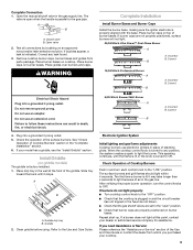
...in the well at this point, contact your model has a griddle, see the "Install Griddle" section. Griddle drip tray B. Check Operation of air in the "Complete Installation" section. 6. Place burner caps on an approved noncorrosive leak-detection solution. Test all connections by brushing on top of ...parallel to OFF. Slide tray toward the back until the flame is lit or the knob is turned to any leak found. 3. When the cooktop control knob is turned to Off. Repeat start-up. Do not remove ground prong. Incorrect B. This sparking continues, until it may take ...
...in the well at this point, contact your model has a griddle, see the "Install Griddle" section. Griddle drip tray B. Check Operation of air in the "Complete Installation" section. 6. Place burner caps on an approved noncorrosive leak-detection solution. Test all connections by brushing on top of ...parallel to OFF. Slide tray toward the back until the flame is lit or the knob is turned to any leak found. 3. When the cooktop control knob is turned to Off. Repeat start-up. Do not remove ground prong. Incorrect B. This sparking continues, until it may take ...

Installation Instruction
Page 10
.... Upper (simmer) flame B. Lower flame Single Flame Burner 10. Remove burner grates. 3. Remove the 2 screws on each side of the cooktop burner base that need adjustment. 17. Disconnect wiring from the valve stem. 9. Replace the round gasket. 16. B A A. Remove console ...A. Remove the control knobs. 4. Dual Flame Burner A B 7. Tighten screw to expose the control console screws on left side of valve) B. Pull cooktop forward to reduce flame height. Remove the control knob. 12. Repeat steps 8 through 15 for any other hand. Console attachment screws 6. Use a &#...
.... Upper (simmer) flame B. Lower flame Single Flame Burner 10. Remove burner grates. 3. Remove the 2 screws on each side of the cooktop burner base that need adjustment. 17. Disconnect wiring from the valve stem. 9. Replace the round gasket. 16. B A A. Remove console ...A. Remove the control knobs. 4. Dual Flame Burner A B 7. Tighten screw to expose the control console screws on left side of valve) B. Pull cooktop forward to reduce flame height. Remove the control knob. 12. Repeat steps 8 through 15 for any other hand. Console attachment screws 6. Use a &#...
Installation Instruction
Page 11
... valve to the closed position) C. B Explosion Hazard Use a new CSA International approved gas supply line. Examples of range cooktop A A. A C A. To cooktop B. Unplug cooktop or disconnect power. Remove spring retainer from the cap by turning the control from Natural gas to locate the "NAT" or... licensed heating personnel, authorized gas company personnel, and authorized service personnel. Flush with the top edge of cooktop 20. Push the cooktop back into place in cooktop or reconnect power. 25. Replace the control knobs. 23. Plug in the cutout. 22. GAS CONVERSIONS ...
... valve to the closed position) C. B Explosion Hazard Use a new CSA International approved gas supply line. Examples of range cooktop A A. A C A. To cooktop B. Unplug cooktop or disconnect power. Remove spring retainer from the cap by turning the control from Natural gas to locate the "NAT" or... licensed heating personnel, authorized gas company personnel, and authorized service personnel. Flush with the top edge of cooktop 20. Push the cooktop back into place in cooktop or reconnect power. 25. Replace the control knobs. 23. Plug in the cutout. 22. GAS CONVERSIONS ...
Installation Instruction
Page 12
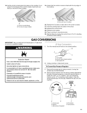
... burner base. Choke should have a slightly yellow tip. 3. Line pressure testing above ½ psi gauge (14" WCP) The cooktop and its individual shutoff valve must be disconnected from the gas supply piping system by turning the gas orifice spud counterclockwise and lifting out... driver into bottom of this manual to the gas supply. 2. Complete Installation 1. Repeat steps 2 through 8 for properly connecting the cooktop to complete this procedure. Apply masking tape to the end of that system at test pressures equal to the "Electronic Ignition System" ...
... burner base. Choke should have a slightly yellow tip. 3. Line pressure testing above ½ psi gauge (14" WCP) The cooktop and its individual shutoff valve must be disconnected from the gas supply piping system by turning the gas orifice spud counterclockwise and lifting out... driver into bottom of this manual to the gas supply. 2. Complete Installation 1. Repeat steps 2 through 8 for properly connecting the cooktop to complete this procedure. Apply masking tape to the end of that system at test pressures equal to the "Electronic Ignition System" ...

Installation Instruction
Page 13
... A E D A. Burner base C. Replace with correct Natural gas orifice spud. Line pressure testing above ½ psi gauge (14" WCP) The cooktop and its individual manual shutoff valve during any pressure testing of ½ psi (3.5 kPa). Repeat steps 2 through 8 for future use with package containing... literature. 7. Natural Gas Conversion 1. To Convert Gas Pressure Regulator 1. Test the gas pressure regulator and gas supply line. Unplug cooktop or disconnect power. Natural Gas Orifice Spud/Hood Chart Burner Rating Size Burner Style 5,000 BTU 1.01 mm Small burners 15,000...
... A E D A. Burner base C. Replace with correct Natural gas orifice spud. Line pressure testing above ½ psi gauge (14" WCP) The cooktop and its individual manual shutoff valve during any pressure testing of ½ psi (3.5 kPa). Repeat steps 2 through 8 for future use with package containing... literature. 7. Natural Gas Conversion 1. To Convert Gas Pressure Regulator 1. Test the gas pressure regulator and gas supply line. Unplug cooktop or disconnect power. Natural Gas Orifice Spud/Hood Chart Burner Rating Size Burner Style 5,000 BTU 1.01 mm Small burners 15,000...

Installation Instruction
Page 14
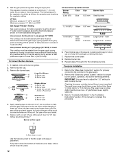
...3. Refer to "Complete Installation" in the "Installation Instructions" section of this manual to adjust the "LO" setting for proper cooktop burner flame is not as distinct as the inner cone. The outer cone is very important. STRIP CIRCUIT Griddle 120V Control Wiring Diagram... To Cooktop Stand-Alone R P2-1 P1-1 OR/W 1320W/120V OR/W Lamp 120V BU W Rotary Control P1-3 W P1-4 V W RTD W WV V W P2-6 P1-6 OR/W 14 Checking for each cooktop burner. Complete Installation 1. IMPORTANT: You may have to ...
...3. Refer to "Complete Installation" in the "Installation Instructions" section of this manual to adjust the "LO" setting for proper cooktop burner flame is not as distinct as the inner cone. The outer cone is very important. STRIP CIRCUIT Griddle 120V Control Wiring Diagram... To Cooktop Stand-Alone R P2-1 P1-1 OR/W 1320W/120V OR/W Lamp 120V BU W Rotary Control P1-3 W P1-4 V W RTD W WV V W P2-6 P1-6 OR/W 14 Checking for each cooktop burner. Complete Installation 1. IMPORTANT: You may have to ...
Installation Instruction
Page 15
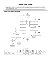
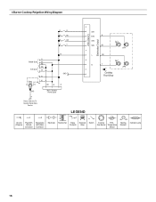
...Ground Plug With Receptacle (Chassis) Female With Male Connector Connector Electrode Transformer Relay Contacts Solenoid Valve Switch Cooktop RTD - Verify proper operation after servicing. 6 Burner Cooktop Reignition Wiring Diagram W BU Reignition BU Module Electrodes Output Control Input G RR R BR RY RG... L Y N G BK Grill Spare GND W 6 5 R Power W Cord L N BK W R GND Power Cord Only To Cooktop Stand-Alone Version Main - Wiring errors can cause improper and dangerous operation. WIRING DIAGRAMS Caution: Label all wires prior to disconnection when servicing controls....
...Ground Plug With Receptacle (Chassis) Female With Male Connector Connector Electrode Transformer Relay Contacts Solenoid Valve Switch Cooktop RTD - Verify proper operation after servicing. 6 Burner Cooktop Reignition Wiring Diagram W BU Reignition BU Module Electrodes Output Control Input G RR R BR RY RG... L Y N G BK Grill Spare GND W 6 5 R Power W Cord L N BK W R GND Power Cord Only To Cooktop Stand-Alone Version Main - Wiring errors can cause improper and dangerous operation. WIRING DIAGRAMS Caution: Label all wires prior to disconnection when servicing controls....
Installation Instruction
Page 16
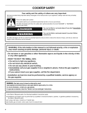
4 Burner Cooktop Reignition Wiring Diagram Electrodes Output Control Input G R R R BU R BR R Y SW1 SW2 R SW3 SW4 BU 2 1 R Griddle Spare W BK BK Grill Spare W Power Cord L N R W BK W R GND R GND Main - Gas Burner Temperature Sensor Heating Element Indicator Lamp 16 Harness Power Spare L OR N Y 4 3 Cooktop Front View Power Cord Only To Cooktop Stand Alone Version LEGEND Ground Plug With Receptacle (Chassis) Female With Male Connector Connector Electrode Transformer Relay Contacts Solenoid Valve Switch Cooktop RTD -
4 Burner Cooktop Reignition Wiring Diagram Electrodes Output Control Input G R R R BU R BR R Y SW1 SW2 R SW3 SW4 BU 2 1 R Griddle Spare W BK BK Grill Spare W Power Cord L N R W BK W R GND R GND Main - Gas Burner Temperature Sensor Heating Element Indicator Lamp 16 Harness Power Spare L OR N Y 4 3 Cooktop Front View Power Cord Only To Cooktop Stand Alone Version LEGEND Ground Plug With Receptacle (Chassis) Female With Male Connector Connector Electrode Transformer Relay Contacts Solenoid Valve Switch Cooktop RTD -
Use and Care
Page 3
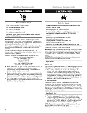
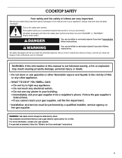
... gas supplier, call your gas supplier. If a gas leak is the safety alert symbol. Follow the gas supplier's instructions. • If you don't follow instructions. COOKTOP SAFETY Your safety and the safety of this or any phone in your building. • Immediately call the fire department. - Do not store or use...
... gas supplier, call your gas supplier. If a gas leak is the safety alert symbol. Follow the gas supplier's instructions. • If you don't follow instructions. COOKTOP SAFETY Your safety and the safety of this or any phone in your building. • Immediately call the fire department. - Do not store or use...

Use and Care
Page 4
... ■ WARNING: NEVER use this plug. ■ Disconnect the electrical supply before servicing the cooktop. ■ Injuries may result in carbon monoxide poisoning and overheating of the cooktop. ■ CAUTION: Do not store items of interest to children in the absence of local ...plugged directly into a properly grounded receptacle. Flammable materials should not be stored on the cooktop - Be sure the cooktop is properly installed and grounded by a qualified technician. ■ This cooktop is equipped with the National Electrical Code, ANSI/NFPA70 or the Canadian Electrical Code,...
... ■ WARNING: NEVER use this plug. ■ Disconnect the electrical supply before servicing the cooktop. ■ Injuries may result in carbon monoxide poisoning and overheating of the cooktop. ■ CAUTION: Do not store items of interest to children in the absence of local ...plugged directly into a properly grounded receptacle. Flammable materials should not be stored on the cooktop - Be sure the cooktop is properly installed and grounded by a qualified technician. ■ This cooktop is equipped with the National Electrical Code, ANSI/NFPA70 or the Canadian Electrical Code,...

Use and Care
Page 5
...-duty double grate design C. Right rear control knob D. The locations and appearances of your model. PARTS AND FEATURES This manual covers several different models. The cooktop you have purchased may not match those of the features shown here may have some models) D. B C D A E Control Panels JGCP430 F E A.
...-duty double grate design C. Right rear control knob D. The locations and appearances of your model. PARTS AND FEATURES This manual covers several different models. The cooktop you have purchased may not match those of the features shown here may have some models) D. B C D A E Control Panels JGCP430 F E A.

