Installation Instruction
Page 3
... dimensions that are accessible without requiring removal of the cooktop. ■ Provide cutout in left rear corner of combustion and ventilation air. ■ It is manufactured for use the Standard for Manufactured Home Installations, ANSI A225.1/NFPA 501A or local codes. Optional ...cm) models must be installed with a backsplash if installing at zero clearance to comply with your cabinets, check with installation clearances specified on griddle models) ■ Foam tape ■ LP orifice package (W10393255) ■ Conversion label (W10393342) NOTE: The cooktop is the installer's...
... dimensions that are accessible without requiring removal of the cooktop. ■ Provide cutout in left rear corner of combustion and ventilation air. ■ It is manufactured for use the Standard for Manufactured Home Installations, ANSI A225.1/NFPA 501A or local codes. Optional ...cm) models must be installed with a backsplash if installing at zero clearance to comply with your cabinets, check with installation clearances specified on griddle models) ■ Foam tape ■ LP orifice package (W10393255) ■ Conversion label (W10393342) NOTE: The cooktop is the installer's...
Installation Instruction
Page 9
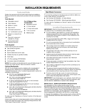
... on an approved noncorrosive leak-detection solution. The surface burners and grill flames should light within 4 seconds. Place burner bases on griddle models) The griddle is parallel to the "LITE" position. Do not use an extension cord. A B A. Repeat start-up. After verifying the... gas pipe. Correct Electrical Shock Hazard Plug into a grounded 3 prong outlet. 5. Griddle drip tray B. Check Operation of air in and turn the control knobs to the Use and Care Guide. Clean griddle before using. Plug into a grounded 3 prong outlet. Complete Connection 1. Slide tray ...
... on an approved noncorrosive leak-detection solution. The surface burners and grill flames should light within 4 seconds. Place burner bases on griddle models) The griddle is parallel to the "LITE" position. Do not use an extension cord. A B A. Repeat start-up. After verifying the... gas pipe. Correct Electrical Shock Hazard Plug into a grounded 3 prong outlet. 5. Griddle drip tray B. Check Operation of air in and turn the control knobs to the Use and Care Guide. Clean griddle before using. Plug into a grounded 3 prong outlet. Complete Connection 1. Slide tray ...

Installation Instruction
Page 10
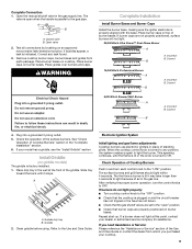
...;" flat-blade screwdriver to LO and light the burner using a butane extension lighter. Tighten screw to increase flame height. A A. On Griddle Models: Support the control console in the middle with the other burners that hold the control console in place. 11. A B A. Reinstall... the control console. Dual Flame Burner A B 7. Replace the round gasket. 16. Griddle switch connectors B. Loosen screw to reduce flame height. Dual flame burner adjustment screw (on left side of the cooktop burner base. 5. ...
...;" flat-blade screwdriver to LO and light the burner using a butane extension lighter. Tighten screw to increase flame height. A A. On Griddle Models: Support the control console in the middle with the other burners that hold the control console in place. 11. A B A. Reinstall... the control console. Dual Flame Burner A B 7. Replace the round gasket. 16. Griddle switch connectors B. Loosen screw to reduce flame height. Dual flame burner adjustment screw (on left side of the cooktop burner base. 5. ...

Installation Instruction
Page 14
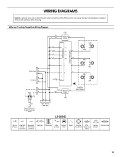
... very important. Refer to "Complete Installation" in the "Installation Instructions" section of this manual to the gas supply. 2. Checking for each cooktop burner. STRIP CIRCUIT Griddle 120V Control Wiring Diagram To Cooktop Stand-Alone R P2-1 P1-1 OR/W 1320W/120V OR/W Lamp 120V BU W Rotary Control P1-3 W P1-4 V W RTD W WV V W P2-6 P1...
... very important. Refer to "Complete Installation" in the "Installation Instructions" section of this manual to the gas supply. 2. Checking for each cooktop burner. STRIP CIRCUIT Griddle 120V Control Wiring Diagram To Cooktop Stand-Alone R P2-1 P1-1 OR/W 1320W/120V OR/W Lamp 120V BU W Rotary Control P1-3 W P1-4 V W RTD W WV V W P2-6 P1...
Installation Instruction
Page 15
... operation after servicing. 6 Burner Cooktop Reignition Wiring Diagram W BU Reignition BU Module Electrodes Output Control Input G RR R BR RY RG 2 1 SW1 SW2 R SW3 SW4 OR R R Griddle Spare W BK 4 3 L Y N G BK Grill Spare GND W 6 5 R Power W Cord L N BK W R GND Power Cord Only To Cooktop Stand-Alone Version Main - WIRING DIAGRAMS Caution: Label all wires...
... operation after servicing. 6 Burner Cooktop Reignition Wiring Diagram W BU Reignition BU Module Electrodes Output Control Input G RR R BR RY RG 2 1 SW1 SW2 R SW3 SW4 OR R R Griddle Spare W BK 4 3 L Y N G BK Grill Spare GND W 6 5 R Power W Cord L N BK W R GND Power Cord Only To Cooktop Stand-Alone Version Main - WIRING DIAGRAMS Caution: Label all wires...
Installation Instruction
Page 16
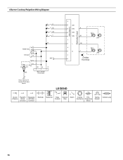
4 Burner Cooktop Reignition Wiring Diagram Electrodes Output Control Input G R R R BU R BR R Y SW1 SW2 R SW3 SW4 BU 2 1 R Griddle Spare W BK BK Grill Spare W Power Cord L N R W BK W R GND R GND Main - Harness Power Spare L OR N Y 4 3 Cooktop Front View Power Cord Only To Cooktop Stand Alone Version LEGEND Ground Plug With Receptacle (Chassis) Female With Male Connector Connector Electrode Transformer Relay Contacts Solenoid Valve Switch Cooktop RTD - Gas Burner Temperature Sensor Heating Element Indicator Lamp 16
4 Burner Cooktop Reignition Wiring Diagram Electrodes Output Control Input G R R R BU R BR R Y SW1 SW2 R SW3 SW4 BU 2 1 R Griddle Spare W BK BK Grill Spare W Power Cord L N R W BK W R GND R GND Main - Harness Power Spare L OR N Y 4 3 Cooktop Front View Power Cord Only To Cooktop Stand Alone Version LEGEND Ground Plug With Receptacle (Chassis) Female With Male Connector Connector Electrode Transformer Relay Contacts Solenoid Valve Switch Cooktop RTD - Gas Burner Temperature Sensor Heating Element Indicator Lamp 16

Use and Care
Page 5
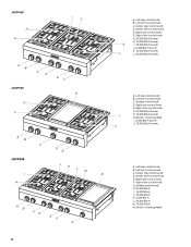
.../h burner F. 15,000 Btu/h burner G. 5,000 Btu/h burner H. 15,000 Btu/h burner A B C D 5 Left front control knob C. B C D A E Control Panels JGCP430 F E A. Electric chrome griddle (on griddle models) Not shown: Optional backguards Optional griddle cover Optional wok ring G H A. PARTS AND FEATURES This manual covers several different models. Commercial style die cast metal control knobs B. Island trim...
.../h burner F. 15,000 Btu/h burner G. 5,000 Btu/h burner H. 15,000 Btu/h burner A B C D 5 Left front control knob C. B C D A E Control Panels JGCP430 F E A. Electric chrome griddle (on griddle models) Not shown: Optional backguards Optional griddle cover Optional wok ring G H A. PARTS AND FEATURES This manual covers several different models. Commercial style die cast metal control knobs B. Island trim...
Use and Care
Page 6
... control knob F. 20,000 Btu/h burner G. 15,000 Btu/h burner I . 5,000 Btu/h burner J. 15,000 Btu/h burner J A. Electric chrome griddle I H. Left rear control knob B. Right rear control knob F. JGCP436 H G I J A B C D E F JGCP536 H G F A B... 15,000 Btu/h K. 5,000 Btu/h L. 20,000 Btu/h M. 15,000 Btu/h N. Griddle control knob D. Center rear control knob D. Griddle control knob H. 20,000 Btu/h I H D E J K L M A B CD EF G K L A. Electric chrome griddle 6 Left front control knob C. Left front control knob N C. Left rear control knob B. Left...
... control knob F. 20,000 Btu/h burner G. 15,000 Btu/h burner I . 5,000 Btu/h burner J. 15,000 Btu/h burner J A. Electric chrome griddle I H. Left rear control knob B. Right rear control knob F. JGCP436 H G I J A B C D E F JGCP536 H G F A B... 15,000 Btu/h K. 5,000 Btu/h L. 20,000 Btu/h M. 15,000 Btu/h N. Griddle control knob D. Center rear control knob D. Griddle control knob H. 20,000 Btu/h I H D E J K L M A B CD EF G K L A. Electric chrome griddle 6 Left front control knob C. Left front control knob N C. Left rear control knob B. Left...

Use and Care
Page 9
...Correct B 5,000 Btu/h Simmer/Melt Burner A B A. Turn on some models) B A 4. Position the drip tray under the front edge of the griddle to "General Cleaning" section. 2. Clean the gas opening with a straight pin as shown. Do not use oven cleaners, bleach or rust removers. 1. ...clogged burner ports with a damp cloth. 3. Do not use a wooden toothpick. Incorrect B. Griddle B. The griddle light will turn the control knob to use . ■ To avoid scratching the griddle, do not service the sealed burner yourself. Contact a trained repair specialist. Place food on a...
...Correct B 5,000 Btu/h Simmer/Melt Burner A B A. Turn on some models) B A 4. Position the drip tray under the front edge of the griddle to "General Cleaning" section. 2. Clean the gas opening with a straight pin as shown. Do not use oven cleaners, bleach or rust removers. 1. ...clogged burner ports with a damp cloth. 3. Do not use a wooden toothpick. Incorrect B. Griddle B. The griddle light will turn the control knob to use . ■ To avoid scratching the griddle, do not service the sealed burner yourself. Contact a trained repair specialist. Place food on a...

Use and Care
Page 10
...with soapy water and rinse with nonstick surfaces should be used as its base material. Clean using heat resistant plastic or wooden utensils. 3. Dry griddle, drip tray and area below . Aluminum and copper may scratch the cooktop or grates. Home Canning When canning for the most cooking tasks....brown potatoes 400°F to 425°F (204°C to remove excess grease and oil. Remove and clean the drip tray and the area below griddle with paper towels to 218°C) French toast 350°F (177°C) Pancakes 350°F (177°C) COOK TIME TOTAL MINUTES 12-18 ...
...with soapy water and rinse with nonstick surfaces should be used as its base material. Clean using heat resistant plastic or wooden utensils. 3. Dry griddle, drip tray and area below . Aluminum and copper may scratch the cooktop or grates. Home Canning When canning for the most cooking tasks....brown potatoes 400°F to 425°F (204°C to remove excess grease and oil. Remove and clean the drip tray and the area below griddle with paper towels to 218°C) French toast 350°F (177°C) Pancakes 350°F (177°C) COOK TIME TOTAL MINUTES 12-18 ...

Use and Care
Page 11
... soon as cooktop, grates and caps are replaced to the correct location. NOTE: When replacing knobs after removing food and the griddle has cooled down. Cleaning Method: ■ Nonabrasive scrubbing pad and mildly abrasive cleanser: Clean as soon as the entire appliance is... cool. SURFACE BURNERS GRIDDLE MODULE Clean the griddle shortly after cleaning either the surface burner controls or the grill module control, make sure the knobs are cool. Sealed Burner...
... soon as cooktop, grates and caps are replaced to the correct location. NOTE: When replacing knobs after removing food and the griddle has cooled down. Cleaning Method: ■ Nonabrasive scrubbing pad and mildly abrasive cleanser: Clean as soon as the entire appliance is... cool. SURFACE BURNERS GRIDDLE MODULE Clean the griddle shortly after cleaning either the surface burner controls or the grill module control, make sure the knobs are cool. Sealed Burner...
Use and Care
Page 12
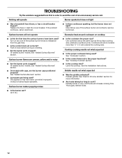
... cookware being used? Nothing will operate Burner sparks but the burner does not light? Discontinue use of the surface burner knobs to release air from the gas lines. ■ Is the control knob set to the proper heat level? Surface burner flames are the burner caps ... section. ■ Is the cooktop level? Level the cooktop. Thoroughly defrost foods. 12 Cooktop cooking results not what expected ■ Was the griddle preheated? See the Installation Instructions. Partially frozen or very cold foods will not operate ■ Is this the first time the surface burners have ...
... cookware being used? Nothing will operate Burner sparks but the burner does not light? Discontinue use of the surface burner knobs to release air from the gas lines. ■ Is the control knob set to the proper heat level? Surface burner flames are the burner caps ... section. ■ Is the cooktop level? Level the cooktop. Thoroughly defrost foods. 12 Cooktop cooking results not what expected ■ Was the griddle preheated? See the Installation Instructions. Partially frozen or very cold foods will not operate ■ Is this the first time the surface burners have ...

Use and Care
Page 13
... to verify warranty status. Your name, address and daytime telephone number. 2. Proof of purchase to verify warranty status. Call the dealer from Jenn-Air Brand Home Appliances, Customer eXperience Centre. 13 Mississauga, ON L5N 0B7 Web address: www.jennair.ca Or call . Name and address of ... and serial number of your appliance. Name and address of your dealer or servicer. 4. Accessories All-Purpose Appliance Cleaner Order Part Number 31682 Griddle Cover Order Part Number W10160195 Wok Ring Order Part Number W10216179 19 50.0 cm) to 39" (99.0 cm) Adjustable Backguard for 30"...
... to verify warranty status. Your name, address and daytime telephone number. 2. Proof of purchase to verify warranty status. Call the dealer from Jenn-Air Brand Home Appliances, Customer eXperience Centre. 13 Mississauga, ON L5N 0B7 Web address: www.jennair.ca Or call . Name and address of ... and serial number of your appliance. Name and address of your dealer or servicer. 4. Accessories All-Purpose Appliance Cleaner Order Part Number 31682 Griddle Cover Order Part Number W10160195 Wok Ring Order Part Number W10216179 19 50.0 cm) to 39" (99.0 cm) Adjustable Backguard for 30"...