
Instruction Manual
Page 3
...a diameter of 5 mm2 (AWG 10) or greater.) • When more than one power amplifier are going to be used , calculate the combined impedance of the speakers and then connect suitable speakers to be connected should be used , use a power supply wiring wire and protective fuse of greater... blown fuses etc. • If a buzzing noise is heard from the speakers when the engine is running, connect a line noise filter (optional) to each amplifier. ■ Speaker Selection • The rated input power of the speakers that are going to the vehicle's wiring harness, it depletes the battery....
...a diameter of 5 mm2 (AWG 10) or greater.) • When more than one power amplifier are going to be used , calculate the combined impedance of the speakers and then connect suitable speakers to be connected should be used , use a power supply wiring wire and protective fuse of greater... blown fuses etc. • If a buzzing noise is heard from the speakers when the engine is running, connect a line noise filter (optional) to each amplifier. ■ Speaker Selection • The rated input power of the speakers that are going to the vehicle's wiring harness, it depletes the battery....

Instruction Manual
Page 4
...this control according to the pre-output level of the center unit connected with all the systems. 9 Speaker output terminals • Stereo Connections: When you wish to use the unit as a stereo amplifier, stereo connections are used . (Make connections to the LEFT channel 9 and the RIGHT channel ·... the combined impedance is 4Ω or greater. 2CAUTION The rated input of the speakers should have a maximum power output of no less than 40 W. • Do not connect the speaker output leads from a power amplifier (Optional) to the in the instruction manual of the center unit. 3 LINE ...
...this control according to the pre-output level of the center unit connected with all the systems. 9 Speaker output terminals • Stereo Connections: When you wish to use the unit as a stereo amplifier, stereo connections are used . (Make connections to the LEFT channel 9 and the RIGHT channel ·... the combined impedance is 4Ω or greater. 2CAUTION The rated input of the speakers should have a maximum power output of no less than 40 W. • Do not connect the speaker output leads from a power amplifier (Optional) to the in the instruction manual of the center unit. 3 LINE ...

Instruction Manual
Page 5
...does not light when the power is not connected to a metal part serving as an electrical ground passing electricity to the speaker output. • When the internal temperature is high and unit won't operate. • When a ground wire of ...• Subwoofer system: L CENTER UNIT R Left speaker L R Right speaker L R Subwoofer (Bridged) English 5 When the protection function is triggered, the Power indicator goes off and the amplifier stops operating. • When a speaker wire may be short-circuited. • When a speaker output contacts ground. • When the unit malfunctions...
...does not light when the power is not connected to a metal part serving as an electrical ground passing electricity to the speaker output. • When the internal temperature is high and unit won't operate. • When a ground wire of ...• Subwoofer system: L CENTER UNIT R Left speaker L R Right speaker L R Subwoofer (Bridged) English 5 When the protection function is triggered, the Power indicator goes off and the amplifier stops operating. • When a speaker wire may be short-circuited. • When a speaker output contacts ground. • When the unit malfunctions...

Instruction Manual
Page 7
...according to applications, read the instruction manual well to the metal body of the units. 4. Set the unit according to appropriate speaker connectors separately. Connect the input and output wires of the car can cause this order. 6. Do not remove caps from ...connectors to prevent short circuits. • Connect the speaker wires to the intended usage. 3. Connect the negative - Sharing the negative wire of the speaker or grounding speaker wires to select the proper setting and connection. 1. Connect the speaker wires. 5. Connect the power wire, power control ...
...according to applications, read the instruction manual well to the metal body of the units. 4. Set the unit according to appropriate speaker connectors separately. Connect the input and output wires of the car can cause this order. 6. Do not remove caps from ...connectors to prevent short circuits. • Connect the speaker wires to the intended usage. 3. Connect the negative - Sharing the negative wire of the speaker or grounding speaker wires to select the proper setting and connection. 1. Connect the speaker wires. 5. Connect the power wire, power control ...

Instruction Manual
Page 8
Connection ■ RCA cable or Speaker level input connection (RCA cable Connections) RCA cable* CENTER UNIT (CD receiver, etc.) Left input Right input (Speaker level input Connections) Cable Color of the connector Left White White/Black Right Gray Gray/Black Power control wire (Blue/ White) Speaker level input cable Genuine-accessory car stereo (No line output center unit etc.) Car fuse box Battery ACC 8 English
Connection ■ RCA cable or Speaker level input connection (RCA cable Connections) RCA cable* CENTER UNIT (CD receiver, etc.) Left input Right input (Speaker level input Connections) Cable Color of the connector Left White White/Black Right Gray Gray/Black Power control wire (Blue/ White) Speaker level input cable Genuine-accessory car stereo (No line output center unit etc.) Car fuse box Battery ACC 8 English

Instruction Manual
Page 9
■ Speaker wire connection (Stereo Connections) Lead terminal* (Bridged Connections) 25 * Commercially available parts Left speaker Right speaker Speaker (Bridged) 25 ■ Power wire connection 25 Terminal cover Power control wire Battery wire* Ground wire* Protective Fuse* Battery Lead terminal* English 9
■ Speaker wire connection (Stereo Connections) Lead terminal* (Bridged Connections) 25 * Commercially available parts Left speaker Right speaker Speaker (Bridged) 25 ■ Power wire connection 25 Terminal cover Power control wire Battery wire* Ground wire* Protective Fuse* Battery Lead terminal* English 9
Instruction Manual
Page 10
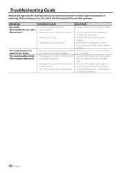
...anything. • The switches may be activated. • Check connections by referring to . 10 English of the terminals and wires well. • A speaker wire is distorted.) wrong + /-polarity. + / - The output level is not set improperly. • Set switches properly by referring to . is... or miswiring. Troubleshooting Guide What might appear to be a malfunction in the car body. The sound quality is bad. • The speakers wire are • Connect the input (or output) cables. (No sound from one side.) disconnected. (Blown fuse.) • Protection...
...anything. • The switches may be activated. • Check connections by referring to . 10 English of the terminals and wires well. • A speaker wire is distorted.) wrong + /-polarity. + / - The output level is not set improperly. • Set switches properly by referring to . is... or miswiring. Troubleshooting Guide What might appear to be a malfunction in the car body. The sound quality is bad. • The speakers wire are • Connect the input (or output) cables. (No sound from one side.) disconnected. (Blown fuse.) • Protection...

