

User Manual
Page 1
...Standards Institute (C95.3 - 1992) WARNING This KENWOOD transceiver generates RF EME while transmitting. To respond to the call . • Receiving Individual Calls (Digital) When you must be either the antenna provided with airline regulations and/or crew instructions. NX-x40 series 1 Align the battery pack with ... The following list before entering the following locations, unless the model is the device that the end of the antenna does not touch your KENWOOD dealer. • Use of the transceiver while you are missing or have been made . transmitting over their ...
...Standards Institute (C95.3 - 1992) WARNING This KENWOOD transceiver generates RF EME while transmitting. To respond to the call . • Receiving Individual Calls (Digital) When you must be either the antenna provided with airline regulations and/or crew instructions. NX-x40 series 1 Align the battery pack with ... The following list before entering the following locations, unless the model is the device that the end of the antenna does not touch your KENWOOD dealer. • Use of the transceiver while you are missing or have been made . transmitting over their ...
Instruction Manual
Page 3
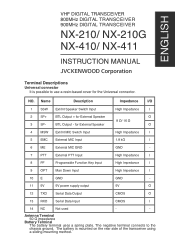
...61527;/ 16 O BTL Output - Name I/O Description Impedance 1 SSW I External MIC Input 1.8 k 6 ME - Not used - Antenna Terminal 50 impedance Battery Terminal The battery terminal uses a spring plate. External MIC GND GND 7 PTT I External PTT Input High Impedance 8 ... Input CMOS 14 NC - O BTL Output + for the Universal connector. VHF DIGITAL TRANSCEIVER NX-210 NX-210G 800MHz DIGITAL TRANSCEIVER NX-410 900MHz DIGITAL TRANSCEIVER NX-411 INSTRUCTION MANUAL Terminal Descriptions Universal connector It is mounted on the rear side of the transceiver...
...61527;/ 16 O BTL Output - Name I/O Description Impedance 1 SSW I External MIC Input 1.8 k 6 ME - Not used - Antenna Terminal 50 impedance Battery Terminal The battery terminal uses a spring plate. External MIC GND GND 7 PTT I External PTT Input High Impedance 8 ... Input CMOS 14 NC - O BTL Output + for the Universal connector. VHF DIGITAL TRANSCEIVER NX-210 NX-210G 800MHz DIGITAL TRANSCEIVER NX-410 900MHz DIGITAL TRANSCEIVER NX-411 INSTRUCTION MANUAL Terminal Descriptions Universal connector It is mounted on the rear side of the transceiver...

Instruction Manual
Page 5
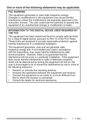
... not occur in accordance with the limits for a Class B digital device, pursuant to Part 15 of the following measures: • Reorient or relocate the receiving antenna. • Increase the separation between the equipment and receiver. • Connect the equipment to an outlet on , the user is connected. • Consult the dealer...
... not occur in accordance with the limits for a Class B digital device, pursuant to Part 15 of the following measures: • Reorient or relocate the receiving antenna. • Increase the separation between the equipment and receiver. • Connect the equipment to an outlet on , the user is connected. • Consult the dealer...
Instruction Manual
Page 7
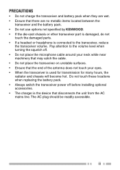
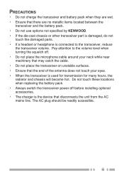
...; Ensure that there are no metallic items located between the transceiver and the battery pack. • Do not use options not specified by KENWOOD. • If the die-cast chassis or other transceiver part is damaged, do not touch the damaged parts. • If a headset or headphone is the... device that the end of the antenna does not touch your eyes. • When the transceiver is used for transmission for many hours, the radiator and chassis will become hot. The AC...
...; Ensure that there are no metallic items located between the transceiver and the battery pack. • Do not use options not specified by KENWOOD. • If the die-cast chassis or other transceiver part is damaged, do not touch the damaged parts. • If a headset or headphone is the... device that the end of the antenna does not touch your eyes. • When the transceiver is used for transmission for many hours, the radiator and chassis will become hot. The AC...
Instruction Manual
Page 9
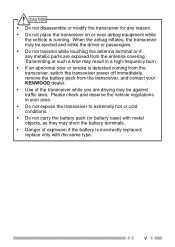
... airbag in your KENWOOD dealer. • Use of explosion if the battery is incorrectly replaced; v Please check and observe the vehicle regulations in flates, the transceiver may be ejected and strike the driver or passengers. • Do not transmit while touching the antenna terminal or if...airbag equipment while the vehicle is detected coming from the transceiver, switch the transceiver power off immediately, remove the battery pack from the antenna covering. replace only with metal objects, as they may result in a high-frequency burn. • If an abnormal odor or smoke...
... airbag in your KENWOOD dealer. • Use of explosion if the battery is incorrectly replaced; v Please check and observe the vehicle regulations in flates, the transceiver may be ejected and strike the driver or passengers. • Do not transmit while touching the antenna terminal or if...airbag equipment while the vehicle is detected coming from the transceiver, switch the transceiver power off immediately, remove the battery pack from the antenna covering. replace only with metal objects, as they may result in a high-frequency burn. • If an abnormal odor or smoke...
Instruction Manual
Page 13
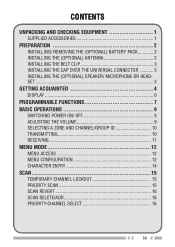
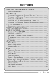
CONTENTS UNPACKING AND CHECKING EQUIPMENT 1 SUPPLIED ACCESSORIES 1 PREPARATION 2 INSTALLING/ REMOVING THE (OPTIONAL) BATTERY PACK 2 INSTALLING THE (OPTIONAL) ANTENNA 2 INSTALLING THE BELT CLIP 3 INSTALLING THE CAP OVER THE UNIVERSAL CONNECTOR 3 INSTALLING THE (OPTIONAL) SPEAKER/ MICROPHONE OR HEADSET ...3 GETTING ACQUAINTED 4 DISPLAY 6 PROGRAMMABLE FUNCTIONS 7 BASIC OPERATIONS 9 ...
CONTENTS UNPACKING AND CHECKING EQUIPMENT 1 SUPPLIED ACCESSORIES 1 PREPARATION 2 INSTALLING/ REMOVING THE (OPTIONAL) BATTERY PACK 2 INSTALLING THE (OPTIONAL) ANTENNA 2 INSTALLING THE BELT CLIP 3 INSTALLING THE CAP OVER THE UNIVERSAL CONNECTOR 3 INSTALLING THE (OPTIONAL) SPEAKER/ MICROPHONE OR HEADSET ...3 GETTING ACQUAINTED 4 DISPLAY 6 PROGRAMMABLE FUNCTIONS 7 BASIC OPERATIONS 9 ...
Instruction Manual
Page 16
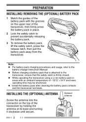
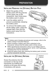
... lower, operating time may be shortened. ◆ Install the battery pack after cleaning the battery pack contacts and the transceiver terminals. INSTALLING THE (OPTIONAL) ANTENNA Screw the antenna into the connector on the upper rear of the transceiver, then firmly press the battery pack in place. 2 Lock the safety catch to... firmly closed. ◆ While operating the transceiver using a Li-ion battery pack in areas with an ambient temperature of the transceiver by holding the antenna at its base and turning it clockwise until secure. Optional...
... lower, operating time may be shortened. ◆ Install the battery pack after cleaning the battery pack contacts and the transceiver terminals. INSTALLING THE (OPTIONAL) ANTENNA Screw the antenna into the connector on the upper rear of the transceiver, then firmly press the battery pack in place. 2 Lock the safety catch to... firmly closed. ◆ While operating the transceiver using a Li-ion battery pack in areas with an ambient temperature of the transceiver by holding the antenna at its base and turning it clockwise until secure. Optional...

Instruction Manual
Page 34
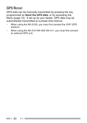
GPS REPORT GPS data can be automatically transmitted at a preset time interval. • When using the NX-210G, you must first connect the VHF/ GPS antenna. • When using the NX-210/ NX-400/ NX-411, you must first connect an external GPS unit. 20 If set up by your dealer, GPS data may be manually transmitted by pressing the key programmed as Send the GPS data, or by accessing the Menu {page 12}.
GPS REPORT GPS data can be automatically transmitted at a preset time interval. • When using the NX-210G, you must first connect the VHF/ GPS antenna. • When using the NX-210/ NX-400/ NX-411, you must first connect an external GPS unit. 20 If set up by your dealer, GPS data may be manually transmitted by pressing the key programmed as Send the GPS data, or by accessing the Menu {page 12}.
Instruction Manual
Page 42
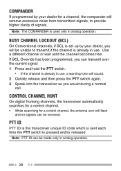
... set up by your dealer, you will be unable to provide higher clarity of signals. COMPANDER If programmed by your dealer for a control channel, the antenna icon will flash and no signals can be received. BUSY CHANNEL LOCKOUT (BCL) On Conventional channels, if BCL is already in analog operation. 28...
... set up by your dealer, you will be unable to provide higher clarity of signals. COMPANDER If programmed by your dealer for a control channel, the antenna icon will flash and no signals can be received. BUSY CHANNEL LOCKOUT (BCL) On Conventional channels, if BCL is already in analog operation. 28...
Instruction Manual 1
Page 3
... the chassis ground. NO. Antenna Terminal 50 Ω impedance Battery Terminal The battery terminal uses a spring plate. The negative terminal connects to use a resin-based cover for External Speaker O 8 Ω/ 16 Ω 3 SP- BTL Output - ENGLISH VHF DIGITAL TRANSCEIVER 800MHz DIGITAL TRANSCEIVER 900MHz DIGITAL TRANSCEIVER NX-210/ NX-210G NX-410/ NX-411 INSTRUCTION MANUAL Terminal...
... the chassis ground. NO. Antenna Terminal 50 Ω impedance Battery Terminal The battery terminal uses a spring plate. The negative terminal connects to use a resin-based cover for External Speaker O 8 Ω/ 16 Ω 3 SP- BTL Output - ENGLISH VHF DIGITAL TRANSCEIVER 800MHz DIGITAL TRANSCEIVER 900MHz DIGITAL TRANSCEIVER NX-210/ NX-210G NX-410/ NX-411 INSTRUCTION MANUAL Terminal...
Instruction Manual 1
Page 5
... change or modification is encouraged to try to correct the interference by one or more of the following measures: • Reorient or relocate the receiving antenna. • Increase the separation between the equipment and receiver. • Connect the equipment to which can generate radio frequency energy and, if not installed and...
... change or modification is encouraged to try to correct the interference by one or more of the following measures: • Reorient or relocate the receiving antenna. • Increase the separation between the equipment and receiver. • Connect the equipment to which can generate radio frequency energy and, if not installed and...
Instruction Manual 1
Page 7
... and battery pack when they are no metallic items located between the transceiver and the battery pack. • Do not use options not specified by KENWOOD. • If the die-cast chassis or other transceiver part is damaged, do not touch the damaged parts. • If a headset or headphone is ...neck while near machinery that may catch the cable. • Do not place the transceiver on unstable surfaces. • Ensure that the end of the antenna does not touch your eyes. • When the transceiver is the device that there are wet. • Ensure that disconnects the unit from the AC...
... and battery pack when they are no metallic items located between the transceiver and the battery pack. • Do not use options not specified by KENWOOD. • If the die-cast chassis or other transceiver part is damaged, do not touch the damaged parts. • If a headset or headphone is ...neck while near machinery that may catch the cable. • Do not place the transceiver on unstable surfaces. • Ensure that the end of the antenna does not touch your eyes. • When the transceiver is the device that there are wet. • Ensure that disconnects the unit from the AC...

Instruction Manual 1
Page 9
... odor or smoke is detected coming from the transceiver, switch the transceiver power off immediately, remove the battery pack from the antenna covering. v Transmitting at such a time may result in your KENWOOD dealer. • Use of explosion if the battery is running. When the airbag inflates, the transceiver may short the battery...
... odor or smoke is detected coming from the transceiver, switch the transceiver power off immediately, remove the battery pack from the antenna covering. v Transmitting at such a time may result in your KENWOOD dealer. • Use of explosion if the battery is running. When the airbag inflates, the transceiver may short the battery...
Instruction Manual 1
Page 13
CONTENTS UNPACKING AND CHECKING EQUIPMENT 1 SUPPLIED ACCESSORIES 1 PREPARATION 2 INSTALLING/ REMOVING THE (OPTIONAL) BATTERY PACK 2 INSTALLING THE (OPTIONAL) ANTENNA 2 INSTALLING THE BELT CLIP 3 INSTALLING THE CAP OVER THE UNIVERSAL CONNECTOR 3 INSTALLING THE (OPTIONAL) SPEAKER/ MICROPHONE OR HEADSET ......3 GETTING ACQUAINTED 4 DISPLAY 6 PROGRAMMABLE FUNCTIONS 7 BASIC OPERATIONS 9 ...
CONTENTS UNPACKING AND CHECKING EQUIPMENT 1 SUPPLIED ACCESSORIES 1 PREPARATION 2 INSTALLING/ REMOVING THE (OPTIONAL) BATTERY PACK 2 INSTALLING THE (OPTIONAL) ANTENNA 2 INSTALLING THE BELT CLIP 3 INSTALLING THE CAP OVER THE UNIVERSAL CONNECTOR 3 INSTALLING THE (OPTIONAL) SPEAKER/ MICROPHONE OR HEADSET ......3 GETTING ACQUAINTED 4 DISPLAY 6 PROGRAMMABLE FUNCTIONS 7 BASIC OPERATIONS 9 ...
Instruction Manual 1
Page 16
..., operating time may be shortened. ◆ Install the battery pack after cleaning the battery pack contacts and the transceiver terminals. INSTALLING THE (OPTIONAL) ANTENNA Optional antenna Screw the antenna into the connector on the upper rear of the transceiver, then firmly press the battery pack in place. 2 Lock the safety catch to prevent... is firmly closed. ◆ While operating the transceiver using a Li-ion battery pack in areas with an ambient temperature of the transceiver by holding the antenna at its base and turning it clockwise until secure. 2
..., operating time may be shortened. ◆ Install the battery pack after cleaning the battery pack contacts and the transceiver terminals. INSTALLING THE (OPTIONAL) ANTENNA Optional antenna Screw the antenna into the connector on the upper rear of the transceiver, then firmly press the battery pack in place. 2 Lock the safety catch to prevent... is firmly closed. ◆ While operating the transceiver using a Li-ion battery pack in areas with an ambient temperature of the transceiver by holding the antenna at its base and turning it clockwise until secure. 2
Instruction Manual 1
Page 34
GPS REPORT GPS data can be manually transmitted by pressing the key programmed as Send the GPS data, or by your dealer, GPS data may be automatically transmitted at a preset time interval. • When using the NX-210G, you must first connect the VHF/ GPS antenna. • When using the NX-210/ NX-400/ NX-411, you must first connect an external GPS unit. 20 If set up by accessing the Menu {page 12}.
GPS REPORT GPS data can be manually transmitted by pressing the key programmed as Send the GPS data, or by your dealer, GPS data may be automatically transmitted at a preset time interval. • When using the NX-210G, you must first connect the VHF/ GPS antenna. • When using the NX-210/ NX-400/ NX-411, you must first connect an external GPS unit. 20 If set up by accessing the Menu {page 12}.
Instruction Manual 1
Page 42
...: 1 Press and hold the PTT switch. • If the channel is pressed and/or released. COMPANDER If programmed by your dealer for a control channel, the antenna icon will sound. 2 Quickly release and then press the PTT switch again. 3 Speak into the transceiver as you would during a normal call.
...: 1 Press and hold the PTT switch. • If the channel is pressed and/or released. COMPANDER If programmed by your dealer for a control channel, the antenna icon will sound. 2 Quickly release and then press the PTT switch again. 3 Speak into the transceiver as you would during a normal call.