

User Manual
Page 1
... KENWOOD Corporation. The RBRC Recycle seal found to comply with the limits for belt clip Universal connector cap • Dressing screw • Packing User guide NX-x00 1 2 1 1 1 1 NX-x10 1 2 1 1 - 1 NX-x20 - - - 1 1 1 1 - - - - 1 NX-x40 1 1 1 1 1 1 1 2 - - - 1 NX-420 1 - - 1 1 1 1 - - - - 1 BASIC OPERATION Selector knob Antenna Display Power switch/ Volume control PTT Switch Microphone Speaker Keypad MIC 1 4 GHI 7 PQRS 2 ABC 5 JKL 8 TUV 0 3 DEF 6 MNO 9 WXYZ # Universal connector Battery Pack Selector knob Antenna PTT Switch Speaker Microphone Display Power switch/ Volume...
... KENWOOD Corporation. The RBRC Recycle seal found to comply with the limits for belt clip Universal connector cap • Dressing screw • Packing User guide NX-x00 1 2 1 1 1 1 NX-x10 1 2 1 1 - 1 NX-x20 - - - 1 1 1 1 - - - - 1 NX-x40 1 1 1 1 1 1 1 2 - - - 1 NX-420 1 - - 1 1 1 1 - - - - 1 BASIC OPERATION Selector knob Antenna Display Power switch/ Volume control PTT Switch Microphone Speaker Keypad MIC 1 4 GHI 7 PQRS 2 ABC 5 JKL 8 TUV 0 3 DEF 6 MNO 9 WXYZ # Universal connector Battery Pack Selector knob Antenna PTT Switch Speaker Microphone Display Power switch/ Volume...
Instruction Manual
Page 3
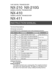
... I Serial Data Input CMOS 14 NC - The negative terminal connects to use a resin-based cover for External Speaker 8 / 16 O BTL Output - Name I/O Description Impedance 1 SSW I Ext/Int Speaker Switch Input High Impedance 2 SP+ 3 SP- Antenna Terminal 50 impedance Battery Terminal The battery terminal uses a spring plate. O BTL Output + for the Universal connector. VHF DIGITAL TRANSCEIVER NX-210 NX-210G 800MHz DIGITAL TRANSCEIVER NX-410 900MHz DIGITAL TRANSCEIVER NX-411 INSTRUCTION MANUAL Terminal Descriptions Universal connector It is mounted on...
... I Serial Data Input CMOS 14 NC - The negative terminal connects to use a resin-based cover for External Speaker 8 / 16 O BTL Output - Name I/O Description Impedance 1 SSW I Ext/Int Speaker Switch Input High Impedance 2 SP+ 3 SP- Antenna Terminal 50 impedance Battery Terminal The battery terminal uses a spring plate. O BTL Output + for the Universal connector. VHF DIGITAL TRANSCEIVER NX-210 NX-210G 800MHz DIGITAL TRANSCEIVER NX-410 900MHz DIGITAL TRANSCEIVER NX-411 INSTRUCTION MANUAL Terminal Descriptions Universal connector It is mounted on...
Instruction Manual
Page 5
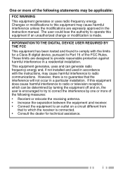
... dealer for a Class B digital device, pursuant to Part 15 of the following measures: • Reorient or relocate the receiving antenna. • Increase the separation between the equipment and receiver. • Connect the equipment to radio communications. i INFORMATION TO THE DIGITAL DEVICE USER REQUIRED BY THE FCC This equipment has been tested and found to comply with the instructions, may cause harmful...
... dealer for a Class B digital device, pursuant to Part 15 of the following measures: • Reorient or relocate the receiving antenna. • Increase the separation between the equipment and receiver. • Connect the equipment to radio communications. i INFORMATION TO THE DIGITAL DEVICE USER REQUIRED BY THE FCC This equipment has been tested and found to comply with the instructions, may cause harmful...
Instruction Manual
Page 7
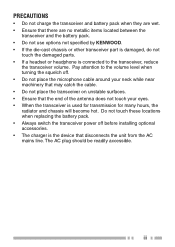
... the damaged parts. • If a headset or headphone is connected to the volume level when turning the squelch off before installing optional accessories. • The charger is used for transmission for many hours, the radiator and chassis will become hot. Do not touch these locations when replacing the battery pack. • Always switch the transceiver power off . • Do not place the microphone cable around your...
... the damaged parts. • If a headset or headphone is connected to the volume level when turning the squelch off before installing optional accessories. • The charger is used for transmission for many hours, the radiator and chassis will become hot. Do not touch these locations when replacing the battery pack. • Always switch the transceiver power off . • Do not place the microphone cable around your...
Instruction Manual
Page 13
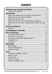
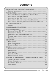
...1 SUPPLIED ACCESSORIES 1 PREPARATION 2 INSTALLING/ REMOVING THE (OPTIONAL) BATTERY PACK 2 INSTALLING THE (OPTIONAL) ANTENNA 2 INSTALLING THE BELT CLIP 3 INSTALLING THE CAP OVER THE UNIVERSAL CONNECTOR 3 INSTALLING THE (OPTIONAL) SPEAKER/ MICROPHONE OR HEADSET ...3 GETTING ACQUAINTED 4 DISPLAY 6 PROGRAMMABLE FUNCTIONS 7 BASIC OPERATIONS 9 SWITCHING POWER ON/ OFF 9 ADJUSTING THE VOLUME 9 SELECTING A ZONE AND CHANNEL/GROUP ID 10 TRANSMITTING 10 RECEIVING 11 MENU MODE 12 MENU ACCESS 12 MENU CONFIGURATION 12 CHARACTER ENTRY 14 SCAN 15 TEMPORARY CHANNEL LOCKOUT 15 PRIORITY SCAN...
...1 SUPPLIED ACCESSORIES 1 PREPARATION 2 INSTALLING/ REMOVING THE (OPTIONAL) BATTERY PACK 2 INSTALLING THE (OPTIONAL) ANTENNA 2 INSTALLING THE BELT CLIP 3 INSTALLING THE CAP OVER THE UNIVERSAL CONNECTOR 3 INSTALLING THE (OPTIONAL) SPEAKER/ MICROPHONE OR HEADSET ...3 GETTING ACQUAINTED 4 DISPLAY 6 PROGRAMMABLE FUNCTIONS 7 BASIC OPERATIONS 9 SWITCHING POWER ON/ OFF 9 ADJUSTING THE VOLUME 9 SELECTING A ZONE AND CHANNEL/GROUP ID 10 TRANSMITTING 10 RECEIVING 11 MENU MODE 12 MENU ACCESS 12 MENU CONFIGURATION 12 CHARACTER ENTRY 14 SCAN 15 TEMPORARY CHANNEL LOCKOUT 15 PRIORITY SCAN...
Instruction Manual
Page 14
... MULTI FREQUENCY) CALLS 21 TRUNKING CALLS (ANALOG 22 EMERGENCY CALLS 22 SCRAMBLER 23 SIGNALING 23 VOICE OPERATED TRANSMISSION (VOX 24 BACKGROUND OPERATIONS 26 CLOCK 26 VIBRATOR 26 TIME-OUT TIMER (TOT 26 BATTERY SAVER 27 KEY LOCK 27 LOW BATTERY WARNING 27 SIGNAL STRENGTH INDICATOR 27 COMPANDER 28 BUSY CHANNEL LOCKOUT (BCL 28 CONTROL CHANNEL HUNT 28 PTT ID 28 VGS-1 OPTIONAL VOICE GUIDE & STORAGE UNIT...
... MULTI FREQUENCY) CALLS 21 TRUNKING CALLS (ANALOG 22 EMERGENCY CALLS 22 SCRAMBLER 23 SIGNALING 23 VOICE OPERATED TRANSMISSION (VOX 24 BACKGROUND OPERATIONS 26 CLOCK 26 VIBRATOR 26 TIME-OUT TIMER (TOT 26 BATTERY SAVER 27 KEY LOCK 27 LOW BATTERY WARNING 27 SIGNAL STRENGTH INDICATOR 27 COMPANDER 28 BUSY CHANNEL LOCKOUT (BCL 28 CONTROL CHANNEL HUNT 28 PTT ID 28 VGS-1 OPTIONAL VOICE GUIDE & STORAGE UNIT...
Instruction Manual
Page 16
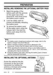
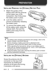
... to the battery charger Instruction Manual. ◆ Before charging a battery pack that is attached to the transceiver, ensure that the safety catch is firmly closed. ◆ While operating the transceiver using a Li-ion battery pack in areas with the grooves on the top of -10°C/ +14°F and lower, operating time may be shortened. ◆ Install the battery pack after...
... to the battery charger Instruction Manual. ◆ Before charging a battery pack that is attached to the transceiver, ensure that the safety catch is firmly closed. ◆ While operating the transceiver using a Li-ion battery pack in areas with the grooves on the top of -10°C/ +14°F and lower, operating time may be shortened. ◆ Install the battery pack after...
Instruction Manual
Page 27
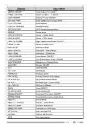
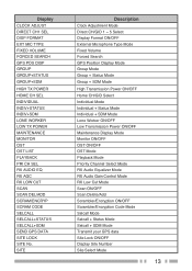
... Channel Select Mode RX Audio Equalizer Mode RX Audio Gain Control Mode RX Low Cut Mode Scan ON/OFF Scan Delete/Add Scrambler/Encryption ON/OFF Scrambler/Encryption Code Mode Selcall Mode Selcall + Status Mode Selcall + SDM Mode Transmit your GPS data Site Lock ON/OFF Display Site Number Site Select Mode 13 Display CLOCK ADJUST DIRECT CH1 SEL DISP FORMAT EXT MIC TYPE FIXED VOLUME FORCED SEARCH GPS POS DISP GROUP GROUP+STATUS GROUP+SDM HIGH TX POWER...
... Channel Select Mode RX Audio Equalizer Mode RX Audio Gain Control Mode RX Low Cut Mode Scan ON/OFF Scan Delete/Add Scrambler/Encryption ON/OFF Scrambler/Encryption Code Mode Selcall Mode Selcall + Status Mode Selcall + SDM Mode Transmit your GPS data Site Lock ON/OFF Display Site Number Site Select Mode 13 Display CLOCK ADJUST DIRECT CH1 SEL DISP FORMAT EXT MIC TYPE FIXED VOLUME FORCED SEARCH GPS POS DISP GROUP GROUP+STATUS GROUP+SDM HIGH TX POWER...
Instruction Manual
Page 33
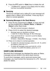
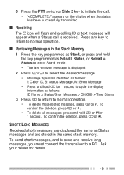
.../GID > Time Stamp 3 Press to return to cycle the display information as follows: I: Caller ID, S: Status Message, M: Short Message • Press and hold or # for details. 19 To send short messages, and to send and receive long messages, you must connect the transceiver to normal operation. ■ Reviewing Messages in the same stack memory. Press any key to...
.../GID > Time Stamp 3 Press to return to cycle the display information as follows: I: Caller ID, S: Status Message, M: Short Message • Press and hold or # for details. 19 To send short messages, and to send and receive long messages, you must connect the transceiver to normal operation. ■ Reviewing Messages in the same stack memory. Press any key to...

Instruction Manual
Page 37
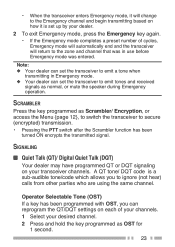
... set the transceiver to emit tones and received signals as normal, or mute the speaker during Emergency operation. SCRAMBLER Press the key programmed as OST for 1 second. 23 SIGNALING ■ Quiet Talk (QT)/ Digital Quiet Talk (DQT) Your dealer may have programmed QT or DQT signaling on each of cycles, Emergency mode will automatically end and the transceiver will change to the Emergency channel...
... set the transceiver to emit tones and received signals as normal, or mute the speaker during Emergency operation. SCRAMBLER Press the key programmed as OST for 1 second. 23 SIGNALING ■ Quiet Talk (QT)/ Digital Quiet Talk (DQT) Your dealer may have programmed QT or DQT signaling on each of cycles, Emergency mode will automatically end and the transceiver will change to the Emergency channel...
Instruction Manual
Page 40
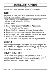
... will sound. If you continuously transmit for an extended duration. Press the key programmed as Vibrator, or access the Menu {page 12}, to exit Clock Adjustment mode. Release the PTT switch. 26 To set the month, day, hour, and minute. 5 Press to exit Clock Adjustment mode. • You can activate a variety of transceiver functions to prevent you from using a channel for a preset time...
... will sound. If you continuously transmit for an extended duration. Press the key programmed as Vibrator, or access the Menu {page 12}, to exit Clock Adjustment mode. Release the PTT switch. 26 To set the month, day, hour, and minute. 5 Press to exit Clock Adjustment mode. • You can activate a variety of transceiver functions to prevent you from using a channel for a preset time...
Instruction Manual
Page 42
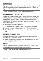
... analog operation. 28 BUSY CHANNEL LOCKOUT (BCL) On Conventional channels, if BCL is set up by your dealer, you will be unable to provide higher clarity of signals. Use a different channel or wait until the channel becomes free. COMPANDER If programmed by your dealer for a control channel, the antenna icon will flash and no signals can be made only in use , a warning tone will sound. 2 Quickly...
... analog operation. 28 BUSY CHANNEL LOCKOUT (BCL) On Conventional channels, if BCL is set up by your dealer, you will be unable to provide higher clarity of signals. Use a different channel or wait until the channel becomes free. COMPANDER If programmed by your dealer for a control channel, the antenna icon will flash and no signals can be made only in use , a warning tone will sound. 2 Quickly...
Instruction Manual 1
Page 3
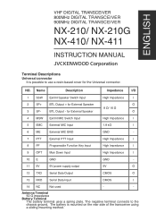
... 5V 5V power supply output 5V O 12 TXD Serial Data Output CMOS O 13 RXD Serial Data Input CMOS I 2 SP+ BTL Output + for the Universal connector. The negative terminal connects to use a resin-based cover for External Speaker O 8 Ω/ 16 Ω 3 SP- Antenna Terminal 50 Ω impedance Battery Terminal The battery terminal uses a spring plate. ENGLISH VHF DIGITAL TRANSCEIVER 800MHz DIGITAL TRANSCEIVER 900MHz DIGITAL TRANSCEIVER NX-210/ NX-210G NX-410/ NX-411 INSTRUCTION MANUAL Terminal Descriptions Universal connector It is mounted on the rear...
... 5V 5V power supply output 5V O 12 TXD Serial Data Output CMOS O 13 RXD Serial Data Input CMOS I 2 SP+ BTL Output + for the Universal connector. The negative terminal connects to use a resin-based cover for External Speaker O 8 Ω/ 16 Ω 3 SP- Antenna Terminal 50 Ω impedance Battery Terminal The battery terminal uses a spring plate. ENGLISH VHF DIGITAL TRANSCEIVER 800MHz DIGITAL TRANSCEIVER 900MHz DIGITAL TRANSCEIVER NX-210/ NX-210G NX-410/ NX-411 INSTRUCTION MANUAL Terminal Descriptions Universal connector It is mounted on the rear...
Instruction Manual 1
Page 7
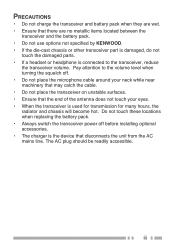
... that disconnects the unit from the AC mains line. iii Do not touch these locations when replacing the battery pack. • Always switch the transceiver power off before installing optional accessories. • The charger is connected to the volume level when turning the squelch off. • Do not place the microphone cable around your eyes. • When the transceiver is used for transmission for many...
... that disconnects the unit from the AC mains line. iii Do not touch these locations when replacing the battery pack. • Always switch the transceiver power off before installing optional accessories. • The charger is connected to the volume level when turning the squelch off. • Do not place the microphone cable around your eyes. • When the transceiver is used for transmission for many...
Instruction Manual 1
Page 13
...SUPPLIED ACCESSORIES 1 PREPARATION 2 INSTALLING/ REMOVING THE (OPTIONAL) BATTERY PACK 2 INSTALLING THE (OPTIONAL) ANTENNA 2 INSTALLING THE BELT CLIP 3 INSTALLING THE CAP OVER THE UNIVERSAL CONNECTOR 3 INSTALLING THE (OPTIONAL) SPEAKER/ MICROPHONE OR HEADSET ......3 GETTING ACQUAINTED 4 DISPLAY 6 PROGRAMMABLE FUNCTIONS 7 BASIC OPERATIONS 9 SWITCHING POWER ON/ OFF 9 ADJUSTING THE VOLUME 9 SELECTING A ZONE AND CHANNEL/GROUP ID 10 TRANSMITTING 10 RECEIVING 11 MENU MODE 12 MENU ACCESS 12 MENU CONFIGURATION 12 CHARACTER ENTRY 14 SCAN 15 TEMPORARY CHANNEL LOCKOUT 15 PRIORITY SCAN...
...SUPPLIED ACCESSORIES 1 PREPARATION 2 INSTALLING/ REMOVING THE (OPTIONAL) BATTERY PACK 2 INSTALLING THE (OPTIONAL) ANTENNA 2 INSTALLING THE BELT CLIP 3 INSTALLING THE CAP OVER THE UNIVERSAL CONNECTOR 3 INSTALLING THE (OPTIONAL) SPEAKER/ MICROPHONE OR HEADSET ......3 GETTING ACQUAINTED 4 DISPLAY 6 PROGRAMMABLE FUNCTIONS 7 BASIC OPERATIONS 9 SWITCHING POWER ON/ OFF 9 ADJUSTING THE VOLUME 9 SELECTING A ZONE AND CHANNEL/GROUP ID 10 TRANSMITTING 10 RECEIVING 11 MENU MODE 12 MENU ACCESS 12 MENU CONFIGURATION 12 CHARACTER ENTRY 14 SCAN 15 TEMPORARY CHANNEL LOCKOUT 15 PRIORITY SCAN...
Instruction Manual 1
Page 14
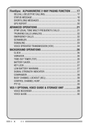
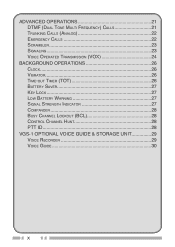
ADVANCED OPERATIONS 21 DTMF (DUAL TONE MULTI FREQUENCY) CALLS 21 TRUNKING CALLS (ANALOG 22 EMERGENCY CALLS 22 SCRAMBLER 23 SIGNALING 23 VOICE OPERATED TRANSMISSION (VOX 24 BACKGROUND OPERATIONS 26 CLOCK 26 VIBRATOR 26 TIME-OUT TIMER (TOT 26 BATTERY SAVER 27 KEY LOCK 27 LOW BATTERY WARNING 27 SIGNAL STRENGTH INDICATOR 27 COMPANDER 28 BUSY CHANNEL LOCKOUT (BCL 28 CONTROL CHANNEL HUNT 28 PTT ID 28 VGS-1 OPTIONAL VOICE GUIDE & STORAGE UNIT 29 VOICE RECORDER 29 VOICE GUIDE 30 x
ADVANCED OPERATIONS 21 DTMF (DUAL TONE MULTI FREQUENCY) CALLS 21 TRUNKING CALLS (ANALOG 22 EMERGENCY CALLS 22 SCRAMBLER 23 SIGNALING 23 VOICE OPERATED TRANSMISSION (VOX 24 BACKGROUND OPERATIONS 26 CLOCK 26 VIBRATOR 26 TIME-OUT TIMER (TOT 26 BATTERY SAVER 27 KEY LOCK 27 LOW BATTERY WARNING 27 SIGNAL STRENGTH INDICATOR 27 COMPANDER 28 BUSY CHANNEL LOCKOUT (BCL 28 CONTROL CHANNEL HUNT 28 PTT ID 28 VGS-1 OPTIONAL VOICE GUIDE & STORAGE UNIT 29 VOICE RECORDER 29 VOICE GUIDE 30 x
Instruction Manual 1
Page 16
... to the battery charger Instruction Manual. ◆ Before charging a battery pack that is attached to the transceiver, ensure that the safety catch is firmly closed. ◆ While operating the transceiver using a Li-ion battery pack in areas with the grooves on the top of -10°C/ +14°F and lower, operating time may be shortened. ◆ Install the battery pack after cleaning...
... to the battery charger Instruction Manual. ◆ Before charging a battery pack that is attached to the transceiver, ensure that the safety catch is firmly closed. ◆ While operating the transceiver using a Li-ion battery pack in areas with the grooves on the top of -10°C/ +14°F and lower, operating time may be shortened. ◆ Install the battery pack after cleaning...
Instruction Manual 1
Page 27
... Channel Select Mode RX Audio Equalizer Mode RX Audio Gain Control Mode RX Low Cut Mode Scan ON/OFF Scan Delete/Add Scrambler/Encryption ON/OFF Scrambler/Encryption Code Mode Selcall Mode Selcall + Status Mode Selcall + SDM Mode Transmit your GPS data Site Lock ON/OFF Display Site Number Site Select Mode 13 Display CLOCK ADJUST DIRECT CH1 SEL DISP FORMAT EXT MIC TYPE FIXED VOLUME FORCED SEARCH GPS POS DISP GROUP GROUP+STATUS GROUP+SDM HIGH TX POWER...
... Channel Select Mode RX Audio Equalizer Mode RX Audio Gain Control Mode RX Low Cut Mode Scan ON/OFF Scan Delete/Add Scrambler/Encryption ON/OFF Scrambler/Encryption Code Mode Selcall Mode Selcall + Status Mode Selcall + SDM Mode Transmit your GPS data Site Lock ON/OFF Display Site Number Site Select Mode 13 Display CLOCK ADJUST DIRECT CH1 SEL DISP FORMAT EXT MIC TYPE FIXED VOLUME FORCED SEARCH GPS POS DISP GROUP GROUP+STATUS GROUP+SDM HIGH TX POWER...
Instruction Manual 1
Page 33
... mode. • The last received message is received. To send short messages, and to send and receive long messages, you must connect the transceiver to a PC. Ask your dealer for 1 second. 6 Press the PTT switch or Side 2 key to initiate the call. • "" appears on the display when the status has been successfully transmitted. ■ Receiving The icon will flash...
... mode. • The last received message is received. To send short messages, and to send and receive long messages, you must connect the transceiver to a PC. Ask your dealer for 1 second. 6 Press the PTT switch or Side 2 key to initiate the call. • "" appears on the display when the status has been successfully transmitted. ■ Receiving The icon will flash...
Instruction Manual 1
Page 37
.../DQT settings on your transceiver channels. SCRAMBLER Press the key programmed as Scrambler/ Encryption, or access the Menu {page 12}, to switch the transceiver to ignore (not hear) calls from other parties who are using the same channel. • When the transceiver enters Emergency mode, it will return to emit tones and received signals as normal, or mute the speaker during Emergency operation...
.../DQT settings on your transceiver channels. SCRAMBLER Press the key programmed as Scrambler/ Encryption, or access the Menu {page 12}, to switch the transceiver to ignore (not hear) calls from other parties who are using the same channel. • When the transceiver enters Emergency mode, it will return to emit tones and received signals as normal, or mute the speaker during Emergency operation...


