
Instruction Manual
Page 2
As a result, we feel strongly that you chose KENWOOD for your land mobile applications. THANK YOU! We believe this product. KENWOOD transceivers incorporate the latest in advanced technology. MODELS COVERED BY THIS MANUAL • TK-690H: VHF FM Transceiver • TK-790: VHF FM Transceiver • TK-790H: VHF FM Transceiver • TK-890: UHF FM Transceiver • TK-890H: UHF FM Transceiver We are grateful you will be pleased with the quality and features of this easy-to-use transceiver will provide dependable communications to keep personnel operating at peak efficiency.
As a result, we feel strongly that you chose KENWOOD for your land mobile applications. THANK YOU! We believe this product. KENWOOD transceivers incorporate the latest in advanced technology. MODELS COVERED BY THIS MANUAL • TK-690H: VHF FM Transceiver • TK-790: VHF FM Transceiver • TK-790H: VHF FM Transceiver • TK-890: UHF FM Transceiver • TK-890H: UHF FM Transceiver We are grateful you will be pleased with the quality and features of this easy-to-use transceiver will provide dependable communications to keep personnel operating at peak efficiency.
Instruction Manual
Page 3
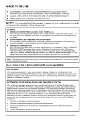
... the dealer for more detailed information. Changes or modifications to this equipment may cause them to which the receiver is in a gasoline service station. Note: This instruction manual covers only the basic functions of any transceiver. NOTICES TO THE USER ◆ GOVERNMENT LAW PROHIBITS THE OPERATION OF UNLICENSED RADIO TRANSMITTERS WITHIN THE TERRITORIES UNDER GOVERNMENT CONTROL. ◆ ILLEGAL OPERATION IS PUNISHABLE BY FINE...
... the dealer for more detailed information. Changes or modifications to this equipment may cause them to which the receiver is in a gasoline service station. Note: This instruction manual covers only the basic functions of any transceiver. NOTICES TO THE USER ◆ GOVERNMENT LAW PROHIBITS THE OPERATION OF UNLICENSED RADIO TRANSMITTERS WITHIN THE TERRITORIES UNDER GOVERNMENT CONTROL. ◆ ILLEGAL OPERATION IS PUNISHABLE BY FINE...
Instruction Manual
Page 4
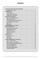
... EQUIPMENT 1 Supplied Accessories 1 PREPARATION 3 Tools Required 3 Power Cable Connection 3 Installing the Transceiver 4 GETTING ACQUAINTED 5 Basic Front Panel (KCH-10 5 Basic Panel Display 6 Full-featured Front Panel (KCH-11 7 Full-featured Panel Display 9 Rear Panel 10 Microphone 10 PROGRAMMABLE FUNCTIONS 11 BASIC OPERATIONS 15 Switching Power ON/ OFF 15 Adjusting the Volume 15 Selecting a Group 15 Selecting a Channel 15 Making a Call 15 DTMF CALLS 16 Manual Dialing...
... EQUIPMENT 1 Supplied Accessories 1 PREPARATION 3 Tools Required 3 Power Cable Connection 3 Installing the Transceiver 4 GETTING ACQUAINTED 5 Basic Front Panel (KCH-10 5 Basic Panel Display 6 Full-featured Front Panel (KCH-11 7 Full-featured Panel Display 9 Rear Panel 10 Microphone 10 PROGRAMMABLE FUNCTIONS 11 BASIC OPERATIONS 15 Switching Power ON/ OFF 15 Adjusting the Volume 15 Selecting a Group 15 Selecting a Channel 15 Making a Call 15 DTMF CALLS 16 Manual Dialing...
Instruction Manual
Page 5
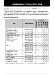
... shipment, file a claim with the carrier immediately. ■ Supplied Accessories Quantity Item Part Number TK-890 (B) TK-890(B) TK-890 TK-790 (B) TK-790 (B) TK-790 TK-690 (B) H H H Microphone and microphone cable 1 Microphone hanger Mounting bracket Power cable assembly Fuse (15 A) Speaker short plug Retaining band Knob Hex-headed screw Self-tapping screw (5 x 16 mm) Self-tapping screw (4 x 16 mm) Spring washer Flat washer Instruction manual T91-0587-X5 J19-1584-X5 J29-0422...
... shipment, file a claim with the carrier immediately. ■ Supplied Accessories Quantity Item Part Number TK-890 (B) TK-890(B) TK-890 TK-790 (B) TK-790 (B) TK-790 TK-690 (B) H H H Microphone and microphone cable 1 Microphone hanger Mounting bracket Power cable assembly Fuse (15 A) Speaker short plug Retaining band Knob Hex-headed screw Self-tapping screw (5 x 16 mm) Self-tapping screw (4 x 16 mm) Spring washer Flat washer Instruction manual T91-0587-X5 J19-1584-X5 J29-0422...
Instruction Manual
Page 7
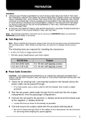
...; Power Cable Connection CAUTION: THE TRANSCEIVER OPERATES IN 12 V NEGATIVE GROUND SYSTEMS ONLY! Note: The following tools are for installing the transceiver: • 6 mm (1/4 inch) or larger electric drill • Drill bits (sizes listed below the mounting surface. PREPARATION WARNING! ◆ VARIOUS ELECTRONIC EQUIPMENT IN YOUR VEHICLE MAY MALFUNCTION IF THEY ARE NOT PROPERLY PROTECTED FROM THE RADIO FREQUENCY ENERGY...
...; Power Cable Connection CAUTION: THE TRANSCEIVER OPERATES IN 12 V NEGATIVE GROUND SYSTEMS ONLY! Note: The following tools are for installing the transceiver: • 6 mm (1/4 inch) or larger electric drill • Drill bits (sizes listed below the mounting surface. PREPARATION WARNING! ◆ VARIOUS ELECTRONIC EQUIPMENT IN YOUR VEHICLE MAY MALFUNCTION IF THEY ARE NOT PROPERLY PROTECTED FROM THE RADIO FREQUENCY ENERGY...
Instruction Manual
Page 8
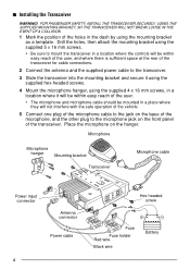
... microphone, and the other plug to the transceiver. 3 Slide the transceiver into the mounting bracket and secure it will be within easy reach of the user, and where there is sufficient space at the rear of the transceiver for cable connections. 2 Connect the antenna and the supplied power cable to the microphone jack on the hanger. FOR PASSENGER SAFETY, INSTALL THE TRANSCEIVER SECURELY, USING THE SUPPLIED MOUNTING...
... microphone, and the other plug to the transceiver. 3 Slide the transceiver into the mounting bracket and secure it will be within easy reach of the user, and where there is sufficient space at the rear of the transceiver for cable connections. 2 Connect the antenna and the supplied power cable to the microphone jack on the hanger. FOR PASSENGER SAFETY, INSTALL THE TRANSCEIVER SECURELY, USING THE SUPPLIED MOUNTING...
Instruction Manual
Page 9
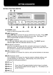
.... r Microphone connector Insert the microphone plug into this control can be programmed with group up/down.) u PF1 key i PF2 key o PF3 key !0 PF4 key Press these keys.) e TX, BUSY indicators The TX (red) indicator lights while transmitting. To remove the microphone, release the screw, then turn the connector clockwise until it . y CH (Channel) control Turn clockwise to increase the channel selection (default setting), and counterclockwise to decrease it becomes free. The default is in use...
.... r Microphone connector Insert the microphone plug into this control can be programmed with group up/down.) u PF1 key i PF2 key o PF3 key !0 PF4 key Press these keys.) e TX, BUSY indicators The TX (red) indicator lights while transmitting. To remove the microphone, release the screw, then turn the connector clockwise until it . y CH (Channel) control Turn clockwise to increase the channel selection (default setting), and counterclockwise to decrease it becomes free. The default is in use...
Instruction Manual
Page 10
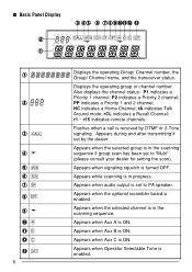
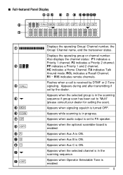
... dealer for setting the scan). Appears when audio output is in the scanning sequence if group scan has been set by DTMF or 2-Tone signaling. Appears when Operator Selectable Tone is ON. Appears when Aux B is enabled. Also displays the channel status: P1 indicates a Priority 1 channel; HC indicates a Home Channel; Appears when Aux A is turned OFF. PP indicates a Priority 1 and 2 channel; Appears when signaling squelch is ON...
... dealer for setting the scan). Appears when audio output is in the scanning sequence if group scan has been set by DTMF or 2-Tone signaling. Appears when Operator Selectable Tone is ON. Appears when Aux B is enabled. Also displays the channel status: P1 indicates a Priority 1 channel; HC indicates a Home Channel; Appears when Aux A is turned OFF. PP indicates a Priority 1 and 2 channel; Appears when signaling squelch is ON...
Instruction Manual
Page 11
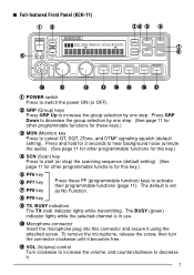
... keys.) e MON (Monitor) key Press to switch the power ON (or OFF). The BUSY (green) indicator lights while the selected channel is set as No Function. To remove the microphone, release the screw, then turn the connector clockwise until it becomes free. !1 VOL (Volume) control Turn clockwise to increase the volume, and counterclockwise to activate their programmable functions {page 11}. o TX, BUSY indicators The TX (red...
... keys.) e MON (Monitor) key Press to switch the power ON (or OFF). The BUSY (green) indicator lights while the selected channel is set as No Function. To remove the microphone, release the screw, then turn the connector clockwise until it becomes free. !1 VOL (Volume) control Turn clockwise to increase the volume, and counterclockwise to activate their programmable functions {page 11}. o TX, BUSY indicators The TX (red...
Instruction Manual
Page 12
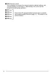
The default is set as No Function. !7 PF5 key 8 !2 CH (Channel) control Turn clockwise to increase the channel selection (default setting), and counterclockwise to decrease it. (Alternatively, this control can be programmed with group up/down.) !3 PF1 key !4 PF2 key !5 PF3 key !6 PF4 key Press these PF (programmable function) keys to activate their programmable functions {page 11}.
The default is set as No Function. !7 PF5 key 8 !2 CH (Channel) control Turn clockwise to increase the channel selection (default setting), and counterclockwise to decrease it. (Alternatively, this control can be programmed with group up/down.) !3 PF1 key !4 PF2 key !5 PF3 key !6 PF4 key Press these PF (programmable function) keys to activate their programmable functions {page 11}.
Instruction Manual
Page 13
... channel is received by the dealer. PP indicates a Priority 1 and 2 channel; TA indicates Talk Around mode; R1 ~ R15 indicates remote channels. Flashes when a call is in the scanning sequence if group scan has been set to PA speaker. Appears while scanning is enabled. 9 Appears when Operator Selectable Tone is in progress. Appears when Aux C is turned OFF. P2 indicates a Priority 2 channel; ■ Full-featured Panel Display...
... channel is received by the dealer. PP indicates a Priority 1 and 2 channel; TA indicates Talk Around mode; R1 ~ R15 indicates remote channels. Flashes when a call is in the scanning sequence if group scan has been set to PA speaker. Appears while scanning is enabled. 9 Appears when Operator Selectable Tone is in progress. Appears when Aux C is turned OFF. P2 indicates a Priority 2 channel; ■ Full-featured Panel Display...
Instruction Manual
Page 14
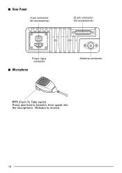
■ Rear Panel 9 pin connector (for accessories) 25 pin connector (for accessories) Power input connector ■ Microphone Antenna connector PTT (Push To Talk) switch Press and hold to receive. 10 Release to transmit, then speak into the microphone.
■ Rear Panel 9 pin connector (for accessories) 25 pin connector (for accessories) Power input connector ■ Microphone Antenna connector PTT (Push To Talk) switch Press and hold to receive. 10 Release to transmit, then speak into the microphone.
Instruction Manual
Page 15
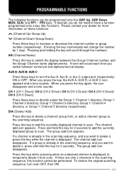
... C output port (respectively) ON or OFF. If desired, you press the key, the AUX A, AUX B, or AUX C icon appears and a tone sounds. Please contact your dealer for 2 seconds to add the currently displayed group to , the scanning sequence. AUX A/ AUX B/ AUX C Press these keys to turn scan OFF, then ON. 11 When you switch between the Group/ Channel number, and the Group/ Channel...
... C output port (respectively) ON or OFF. If desired, you press the key, the AUX A, AUX B, or AUX C icon appears and a tone sounds. Please contact your dealer for 2 seconds to add the currently displayed group to , the scanning sequence. AUX A/ AUX B/ AUX C Press these keys to turn scan OFF, then ON. 11 When you switch between the Group/ Channel number, and the Group/ Channel...
Instruction Manual
Page 16
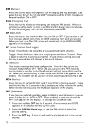
... key to turn the TX and BUSY indicators and the DTMF microphone keypad backlight ON or OFF. If used while scanning, pressing this key to select the pre-programmed Home Channel. The intercom can press the PTT switch to communicate to select the desired setting. 3 Press the OPT key. To change the scrambler code: 1 Press and hold this key to adjust the brightness of the display...
... key to turn the TX and BUSY indicators and the DTMF microphone keypad backlight ON or OFF. If used while scanning, pressing this key to select the pre-programmed Home Channel. The intercom can press the PTT switch to communicate to select the desired setting. 3 Press the OPT key. To change the scrambler code: 1 Press and hold this key to adjust the brightness of the display...
Instruction Manual
Page 17
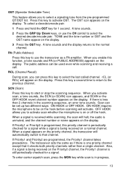
... the OFF HOOK revert channel number appears on the display. When you can be used even while scanning and receiving a call. If there is in the scanning sequence, an error tone sounds. To enter carrier squelch scan, press the MON key while scan is less than a single channel. OST (Operator Selectable Tone) This feature allows you to activate scan whether the microphone is unmuted, and the channel number or name...
... the OFF HOOK revert channel number appears on the display. When you can be used even while scanning and receiving a call. If there is in the scanning sequence, an error tone sounds. To enter carrier squelch scan, press the MON key while scan is less than a single channel. OST (Operator Selectable Tone) This feature allows you to activate scan whether the microphone is unmuted, and the channel number or name...
Instruction Manual
Page 18
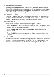
... the normal channel. SP (Speaker Internal/ External) Press this key to select the desired level. 3 Press the SQ key. SPM (Speaker 1-2 Mute) This feature requires dual head configuration. You can manually adjust the squelch level using a repeater. However, all audio will be emitted from the other control head. A tone sounds and SQL (or SQUELCH) appears on the 3-digit display. This function is selected, a tone sounds and the...
... the normal channel. SP (Speaker Internal/ External) Press this key to select the desired level. 3 Press the SQ key. SPM (Speaker 1-2 Mute) This feature requires dual head configuration. You can manually adjust the squelch level using a repeater. However, all audio will be emitted from the other control head. A tone sounds and SQL (or SQUELCH) appears on the 3-digit display. This function is selected, a tone sounds and the...
Instruction Manual
Page 19
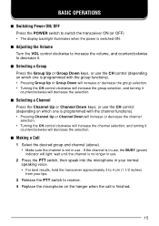
... selection, and turning it counterclockwise will light; BASIC OPERATIONS ■ Switching Power ON/ OFF Press the POWER switch to switch the transceiver ON (or OFF) • The display backlight illuminates when the power is switched ON. ■ Adjusting the Volume Turn the VOL control clockwise to increase the volume, and counterclockwise to receive. 4 Replace the microphone on which one is programmed with the channel functions). • Pressing Channel Up or Channel Down will...
... selection, and turning it counterclockwise will light; BASIC OPERATIONS ■ Switching Power ON/ OFF Press the POWER switch to switch the transceiver ON (or OFF) • The display backlight illuminates when the power is switched ON. ■ Adjusting the Volume Turn the VOL control clockwise to increase the volume, and counterclockwise to receive. 4 Replace the microphone on which one is programmed with the channel functions). • Pressing Channel Up or Channel Down will...
Instruction Manual
Page 20
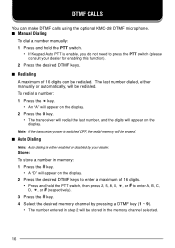
... transceiver power is switched OFF, the redial memory will appear on the display. 2 Press the desired DTMF keys to enter a maximum of 16 digits can make DTMF calls using the optional KMC-28 DTMF microphone. ■ Manual Dialing To dial a number manually: 1 Press and hold the PTT switch, then press 2, 5, 8, 0, , or # to enter A, B, C, D, , or # (respectively). 3 Press the # key. 4 Select the desired memory channel...
... transceiver power is switched OFF, the redial memory will appear on the display. 2 Press the desired DTMF keys to enter a maximum of 16 digits can make DTMF calls using the optional KMC-28 DTMF microphone. ■ Manual Dialing To dial a number manually: 1 Press and hold the PTT switch, then press 2, 5, 8, 0, , or # to enter A, B, C, D, , or # (respectively). 3 Press the # key. 4 Select the desired memory channel...
Instruction Manual
Page 22
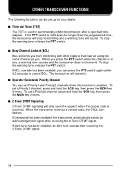
.... To set a Priority1 channel, press and hold the SCN key, then press the MON key 2 times. ■ 2-Tone/ DTMF Signaling 2-Tone/ DTMF signaling will only open the squelch when the proper code is held down for longer than the programmed time, the transceiver will stop transmitting and a warning tone will transmit. ■ Operator Selectable Priority Channel You can press the PTT switch again within...
.... To set a Priority1 channel, press and hold the SCN key, then press the MON key 2 times. ■ 2-Tone/ DTMF Signaling 2-Tone/ DTMF signaling will only open the squelch when the proper code is held down for longer than the programmed time, the transceiver will stop transmitting and a warning tone will transmit. ■ Operator Selectable Priority Channel You can press the PTT switch again within...
Instruction Manual
Page 23
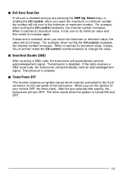
If dead end is selected, when you turn OFF. You must be connected to change . Transmission is enabled. ■ Timed Power OFF This function requires an ignition-sense which must then rotate the CH control counterclockwise to the 9 pin connector on the rear panel of your vehicle OFF, the timer starts. The timer resets when the ignition is disabled. When it reaches its...
If dead end is selected, when you turn OFF. You must be connected to change . Transmission is enabled. ■ Timed Power OFF This function requires an ignition-sense which must then rotate the CH control counterclockwise to the 9 pin connector on the rear panel of your vehicle OFF, the timer starts. The timer resets when the ignition is disabled. When it reaches its...


