
User Manual 1
Page 2
......4 Connecting the power cable 4 Installing the Transceiver 4 ORIENTATION...6 FRONT AND REAR VIEWS 6 DISPLAY...8 PROGRAMMABLE FUNCTIONS 11 BASIC OPERATION...15 SWITCHING POWER ON/ OFF 15 Transceiver Password...15 ADJUSTING THE VOLUME 15 SELECTING A ZONE AND CHANNEL 15 TRANSMITTING...15 RECEIVING...16 Receiving Group Calls 16 Receiving Individual Calls 16 FleetSync: ALPHANUMERIC 2-WAY PAGING FUNCTION 17 SELCALL (SELECTIVE CALLING 17 Transmitting...17 Receiving...17 Identification Codes...17 PAGING CALL...17 SCAN...
......4 Connecting the power cable 4 Installing the Transceiver 4 ORIENTATION...6 FRONT AND REAR VIEWS 6 DISPLAY...8 PROGRAMMABLE FUNCTIONS 11 BASIC OPERATION...15 SWITCHING POWER ON/ OFF 15 Transceiver Password...15 ADJUSTING THE VOLUME 15 SELECTING A ZONE AND CHANNEL 15 TRANSMITTING...15 RECEIVING...16 Receiving Group Calls 16 Receiving Individual Calls 16 FleetSync: ALPHANUMERIC 2-WAY PAGING FUNCTION 17 SELCALL (SELECTIVE CALLING 17 Transmitting...17 Receiving...17 Identification Codes...17 PAGING CALL...17 SCAN...
User Manual 1
Page 4
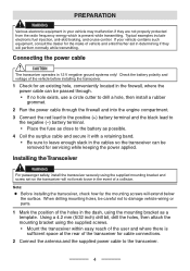
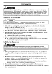
... the power cable through the firewall and into the engine compartment. 3 Connect the red lead to the positive (+) battery terminal and the black lead to the negative (-) battery terminal. • Place the fuse as close to the battery as a template. Check the battery polarity and voltage of a collision. Installing the Transceiver WARNING For passenger safety, install the transceiver securely using the mounting bracket as...
... the power cable through the firewall and into the engine compartment. 3 Connect the red lead to the positive (+) battery terminal and the black lead to the negative (-) battery terminal. • Place the fuse as close to the battery as a template. Check the battery polarity and voltage of a collision. Installing the Transceiver WARNING For passenger safety, install the transceiver securely using the mounting bracket as...

User Manual 1
Page 8
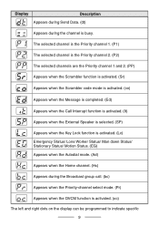
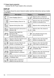
... scan list. (GA) Appears when a zone is removed from the scan list. (Gd) Appears when a channel is added to the scan list. (cA) Appears when a channel is removed from the scan list. (cd) Appears when the Lone Worker function is stunned. (St) Appears when switch the transceiver ON. DISPLAY The display shows the zone/ channel number and the left and right dots show various modes of operation...
... scan list. (GA) Appears when a zone is removed from the scan list. (Gd) Appears when a channel is added to the scan list. (cA) Appears when a channel is removed from the scan list. (cd) Appears when the Lone Worker function is stunned. (St) Appears when switch the transceiver ON. DISPLAY The display shows the zone/ channel number and the left and right dots show various modes of operation...
User Manual 1
Page 9
... External Speaker is selected. (SP) Appears when the Key Lock function is activated. (Lc) Emergency Status/ Lone Worker Status/ Man down Status/ Stationary Status/ Motion Status. (EG) Appears when the Autodial mode. (Ad) Appears when the Home channel. (Hc) Appears during the channel is activated. (oc) The left and right dots on the display can be programmed to indicate specific 9 Display...
... External Speaker is selected. (SP) Appears when the Key Lock function is activated. (Lc) Emergency Status/ Lone Worker Status/ Man down Status/ Stationary Status/ Motion Status. (EG) Appears when the Autodial mode. (Ad) Appears when the Home channel. (Hc) Appears during the channel is activated. (oc) The left and right dots on the display can be programmed to indicate specific 9 Display...
User Manual 1
Page 10
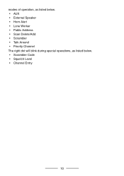
modes of operation, as listed below. • AUX • External Speaker • Horn Alert • Lone Worker • Public Address • Scan Delete/Add • Scrambler • Talk Around • Priority Channel The right dot will blink during special operations, as listed below. • Scrambler Code • Squelch Level • Channel Entry 10
modes of operation, as listed below. • AUX • External Speaker • Horn Alert • Lone Worker • Public Address • Scan Delete/Add • Scrambler • Talk Around • Priority Channel The right dot will blink during special operations, as listed below. • Scrambler Code • Squelch Level • Channel Entry 10
User Manual 1
Page 13
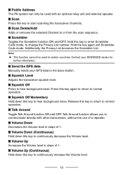
... to communicate directly with an optional relay unit and external speaker. n Volume Down Decreases the Volume level in certain countries. Hold the key again exit Scrambler Code mode. Note: ◆◆ This function cannot be used in steps of 1. n Scan Press this key to start scanning the transceiver channels. n Send the GPS data Manually sends your KENWOOD dealer for further information. Press this key to or from the scan sequence. n Scan Delete/Add...
... to communicate directly with an optional relay unit and external speaker. n Volume Down Decreases the Volume level in certain countries. Hold the key again exit Scrambler Code mode. Note: ◆◆ This function cannot be used in steps of 1. n Scan Press this key to start scanning the transceiver channels. n Send the GPS data Manually sends your KENWOOD dealer for further information. Press this key to or from the scan sequence. n Scan Delete/Add...
User Manual 1
Page 15
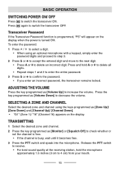
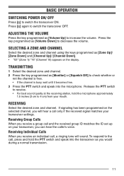
... remains locked. Release the PTT switch to receive. • For best sound quality at the receiving station, hold A or # to delete all digits. • Repeat steps 1 and 2 to enter the entire password. 3 Press S or to increase the volume. To enter the password: 1 Press / to select a digit. • When using the keys programmed as [Monitor] or [Squelch Off] to delete an incorrect digit. SELECTING A ZONE AND CHANNEL Select...
... remains locked. Release the PTT switch to receive. • For best sound quality at the receiving station, hold A or # to delete all digits. • Repeat steps 1 and 2 to enter the entire password. 3 Press S or to increase the volume. To enter the password: 1 Press / to select a digit. • When using the keys programmed as [Monitor] or [Squelch Off] to delete an incorrect digit. SELECTING A ZONE AND CHANNEL Select...
User Manual 1
Page 18
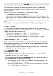
... automatically change to the Priority channel when a call is received on that channel. However, when scanning is added to scan, "cA" appears on the display. Note: ◆◆ To use Scan, there must be at the undesired channel. • The channel is no longer present, at which time Scan resumes. SCAN Scan monitors for a signal on the display during Scan. • When a signal is detected, Scan pauses at that channel, even...
... automatically change to the Priority channel when a call is received on that channel. However, when scanning is added to scan, "cA" appears on the display. Note: ◆◆ To use Scan, there must be at the undesired channel. • The channel is no longer present, at which time Scan resumes. SCAN Scan monitors for a signal on the display during Scan. • When a signal is detected, Scan pauses at that channel, even...
User Manual 1
Page 19
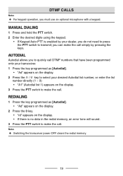
... list number, or enter the list number directly (1 ~ 9) • "A1" (Autodial list 1) appears on the display. • If there is enabled by pressing the keys. MANUAL DIALING 1 Press and hold the PTT switch. 2 Enter the desired digits using the keypad. • If Keypad Auto-PTT is no data in the redial memory, an error tone will sound. 3 Press the PTT switch to select your transceiver. 1 Press the key programmed...
... list number, or enter the list number directly (1 ~ 9) • "A1" (Autodial list 1) appears on the display. • If there is enabled by pressing the keys. MANUAL DIALING 1 Press and hold the PTT switch. 2 Enter the desired digits using the keypad. • If Keypad Auto-PTT is no data in the redial memory, an error tone will sound. 3 Press the PTT switch to select your transceiver. 1 Press the key programmed...
User Manual 1
Page 20
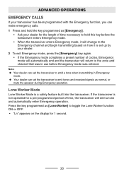
... mode, press the [Emergency] key again. • If the Emergency mode completes a preset number of time, the transceiver will emit a tone and automatically enter Emergency operation. ADVANCED OPERATIONS EMERGENCY CALLS If your transceiver has been programmed with the Emergency function, you can set the transceiver to emit tones and received signals as [Lone Worker] to the zone and channel that was in use...
... mode, press the [Emergency] key again. • If the Emergency mode completes a preset number of time, the transceiver will emit a tone and automatically enter Emergency operation. ADVANCED OPERATIONS EMERGENCY CALLS If your transceiver has been programmed with the Emergency function, you can set the transceiver to emit tones and received signals as [Lone Worker] to the zone and channel that was in use...
User Manual 1
Page 21
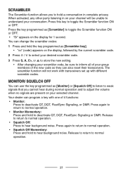
... operation and to adjust the volume when no signals are present on your conversation. Release to return to toggle the Scrambler function ON or OFF. The scrambler function will not work with transceivers set up with one of the new code so they can use the key programmed as [Monitor] or [Squelch Off] to listen to weak signals that you to hold the key programmed...
... operation and to adjust the volume when no signals are present on your conversation. Release to return to toggle the Scrambler function ON or OFF. The scrambler function will not work with transceivers set up with one of the new code so they can use the key programmed as [Monitor] or [Squelch Off] to listen to weak signals that you to hold the key programmed...
User Manual 1
Page 22
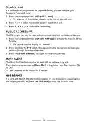
... installed on your transceiver, you can readjust your transceiver's squelch level: 1 Press the key programmed as [Squelch Level]. • "SL" appears on the display for 1 second. Squelch Level If a key has been programmed as [Squelch Level], you can press the key programmed as [Send the GPS data] to store the new setting. HORN ALERT The Horn Alert function can only be used with an optional relay unit and external speaker...
... installed on your transceiver, you can readjust your transceiver's squelch level: 1 Press the key programmed as [Squelch Level]. • "SL" appears on the display for 1 second. Squelch Level If a key has been programmed as [Squelch Level], you can press the key programmed as [Send the GPS data] to store the new setting. HORN ALERT The Horn Alert function can only be used with an optional relay unit and external speaker...
User Manual 1
Page 25
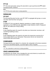
... Card" Group Calling. 2-Tone 2-tone Signaling opens the squelch only when your transceiver receives a call containing matching 2 tones. 5-Tone 5-tone Signaling opens the squelch only when the transceiver receives the 5 tones programmed in your dealer, when changing the zone and channel, an audio voice will announce the new zone and channel number. 25 COMPANDER If programmed by your transceiver. SIGNALING QT/ DQT The Encoder/Decoder function uses...
... Card" Group Calling. 2-Tone 2-tone Signaling opens the squelch only when your transceiver receives a call containing matching 2 tones. 5-Tone 5-tone Signaling opens the squelch only when the transceiver receives the 5 tones programmed in your dealer, when changing the zone and channel, an audio voice will announce the new zone and channel number. 25 COMPANDER If programmed by your transceiver. SIGNALING QT/ DQT The Encoder/Decoder function uses...
User Manual 1
Page 5
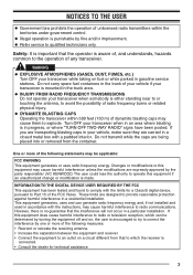
... interference by turning the equipment off and on, the user is made. NOTICES TO THE USER ◆ Government law prohibits the operation of unlicensed radio transmitters within 500 feet (150 m) of dynamite blasting caps may cause harmful interference unless the modifications are designed to which can generate radio frequency energy and, if not installed and used in gasoline service stations. This equipment...
... interference by turning the equipment off and on, the user is made. NOTICES TO THE USER ◆ Government law prohibits the operation of unlicensed radio transmitters within 500 feet (150 m) of dynamite blasting caps may cause harmful interference unless the modifications are designed to which can generate radio frequency energy and, if not installed and used in gasoline service stations. This equipment...
User Manual 1
Page 6
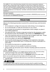
... operates in this equipment on unstable surfaces. • Keep the volume as low as possible to configure the transceiver while driving; The user of this product is too dangerous. • Do not disassemble or modify the transceiver for JVC KENWOOD Corporation. WARNING For passenger safety, install the transceiver securely using the supplied mounting bracket and screw set...
... operates in this equipment on unstable surfaces. • Keep the volume as low as possible to configure the transceiver while driving; The user of this product is too dangerous. • Do not disassemble or modify the transceiver for JVC KENWOOD Corporation. WARNING For passenger safety, install the transceiver securely using the supplied mounting bracket and screw set...
User Manual 1
Page 7
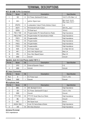
...SPO O External Speaker Output 3 GND - TERMINAL DESCRIPTIONS ACC (D-SUB 15 Pin Connector) Pin No. Input: 10.8 V Max. Name I /O Mic Data Detection Antenna Terminal 50 impedance Specification 13.6 V ±15% Max. 1 A Min. Ground Speaker Jack (3.5 mm Phone Jack) 4 W/ 4 Pin No. Mic Ground 6 MIC I Mic Signal Input 7 HOOK/ RXD I Hook/ PC Serial Data to Radio 8 FNC3 I/O Programmable 9 FNC4 I/O Programmable 10 FNC5 I/O Programmable 11 FNC6 I/O Programmable 12 5MC O DC Power Output 13 HR1 I Ground Microphone Jack Pin No. Input: 16...
...SPO O External Speaker Output 3 GND - TERMINAL DESCRIPTIONS ACC (D-SUB 15 Pin Connector) Pin No. Input: 10.8 V Max. Name I /O Mic Data Detection Antenna Terminal 50 impedance Specification 13.6 V ±15% Max. 1 A Min. Ground Speaker Jack (3.5 mm Phone Jack) 4 W/ 4 Pin No. Mic Ground 6 MIC I Mic Signal Input 7 HOOK/ RXD I Hook/ PC Serial Data to Radio 8 FNC3 I/O Programmable 9 FNC4 I/O Programmable 10 FNC5 I/O Programmable 11 FNC6 I/O Programmable 12 5MC O DC Power Output 13 HR1 I Ground Microphone Jack Pin No. Input: 16...
User Manual 1
Page 8
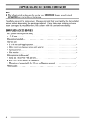
... identify the items listed below before discarding the packing material. If any items are for use by your KENWOOD dealer, an authorized KENWOOD service facility, or the factory. SUPPLIED ACCESSORIES DC power cable (with fuses 1 • 15 A fuse 2 Mounting bracket 1 Screw set • 5 x 16 mm self-tapping screw 4 • M4 x 6 mm hex-headed screw with washer 4 • Spring washer 4 • Flat washer 4 Microphone (with the...
... identify the items listed below before discarding the packing material. If any items are for use by your KENWOOD dealer, an authorized KENWOOD service facility, or the factory. SUPPLIED ACCESSORIES DC power cable (with fuses 1 • 15 A fuse 2 Mounting bracket 1 Screw set • 5 x 16 mm self-tapping screw 4 • M4 x 6 mm hex-headed screw with washer 4 • Spring washer 4 • Flat washer 4 Microphone (with the...
User Manual 1
Page 9
... a hole, then install a rubber grommet. 2 Run the power cable through the firewall and into the engine compartment. 3 Connect the red lead to the positive (+) battery terminal and the black lead to the negative (-) battery terminal. • Place the fuse as close to damage vehicle wiring or parts. 1 Mark the position of the holes in the dash, using the mounting bracket as possible...
... a hole, then install a rubber grommet. 2 Run the power cable through the firewall and into the engine compartment. 3 Connect the red lead to the positive (+) battery terminal and the black lead to the negative (-) battery terminal. • Place the fuse as close to damage vehicle wiring or parts. 1 Mark the position of the holes in the dash, using the mounting bracket as possible...
User Manual 1
Page 12
... connector. Power input connector Connect the DC Power Cable to the scan list. (cA) Appears when the channel is busy. Display Description Display Description Zone Display (Zone 1) Appears when a channel is removed from the scan list. (cd) Channel Display (Channel 16) Appears when the Lone Worker function is activated. (Ln) Appears during Scan. (Sc) Appears when sending data. (dt) Appears during the transceiver is selected. (SP) 10 DISPLAY The display shows the zone/ channel number...
... connector. Power input connector Connect the DC Power Cable to the scan list. (cA) Appears when the channel is busy. Display Description Display Description Zone Display (Zone 1) Appears when a channel is removed from the scan list. (cd) Channel Display (Channel 16) Appears when the Lone Worker function is activated. (Ln) Appears during Scan. (Sc) Appears when sending data. (dt) Appears during the transceiver is selected. (SP) 10 DISPLAY The display shows the zone/ channel number...
User Manual 1
Page 13
.... ADJUSTING THE VOLUME Press the key programmed as [Zone Up]/ [Zone Down] and [Channel Up]/ [Channel Down]. • "G1" (Zone 1)/ "16" (Channel 16) appears on the selected channel, you can hear the caller's voice. Release the PTT switch to 4 cm) from your transceiver settings. To respond to the call, press and hold the microphone approximately 1.5 inches (3 cm to receive. • For best sound...
.... ADJUSTING THE VOLUME Press the key programmed as [Zone Up]/ [Zone Down] and [Channel Up]/ [Channel Down]. • "G1" (Zone 1)/ "16" (Channel 16) appears on the selected channel, you can hear the caller's voice. Release the PTT switch to 4 cm) from your transceiver settings. To respond to the call, press and hold the microphone approximately 1.5 inches (3 cm to receive. • For best sound...


