

User Manual
Page 2
... setting position of this page carefully to the shape of shipping damage. THE EXCLAMATION POINT WITHIN AN EQUILATERAL TRIANGLE IS INTENDED TO ALERT THE USER TO THE PRESENCE OF IMPORTANT OPERATING AND MAINTENANCE (SERVICING) INSTRUCTIONS IN THE LITERATURE ACCOMPANYING THE APPLIANCE. *AC plug adaptor (1) *Use to adapt the plug on the rear panel is shipped. Accessories FM indoor antenna (1) AM loop antenna (1) For VR-506...
... setting position of this page carefully to the shape of shipping damage. THE EXCLAMATION POINT WITHIN AN EQUILATERAL TRIANGLE IS INTENDED TO ALERT THE USER TO THE PRESENCE OF IMPORTANT OPERATING AND MAINTENANCE (SERVICING) INSTRUCTIONS IN THE LITERATURE ACCOMPANYING THE APPLIANCE. *AC plug adaptor (1) *Use to adapt the plug on the rear panel is shipped. Accessories FM indoor antenna (1) AM loop antenna (1) For VR-506...

User Manual
Page 3
... video components 11 Connecting a DVD player (6-channel input) ...... 12 Digital connections 13 Connecting to the AV AUX jacks (VR-506/517/KRF-V6050D only 14 Connecting the antennas 14 Connecting the system control 15 Connecting the speakers 16 Preparing the remote control 18 Preparing for surround sound 19 Speaker settings 19 Operations Operations Normal playback 20 Preparing for playback 20 Listening to a source component 21 Adjusting the sound 21 Recording 22 Recording audio (analog sources 22 Recording video 23 Recording audio (digital sources 23 Listening to use radio...
... video components 11 Connecting a DVD player (6-channel input) ...... 12 Digital connections 13 Connecting to the AV AUX jacks (VR-506/517/KRF-V6050D only 14 Connecting the antennas 14 Connecting the system control 15 Connecting the speakers 16 Preparing the remote control 18 Preparing for surround sound 19 Speaker settings 19 Operations Operations Normal playback 20 Preparing for playback 20 Listening to a source component 21 Adjusting the sound 21 Recording 22 Recording audio (analog sources 22 Recording video 23 Recording audio (digital sources 23 Listening to use radio...

User Manual
Page 4
... outlet for better sound quality and more powerful presence than conventional Dolby Surround. Memory back up your audio and video components, connecting the system can be achieved with conventional surround sound systems. Universal IR (InfraRed) remote control (Except for unprecedented clarity, optimum channel separation and a (wide) dynamic range. Before applying the power Special features True home theater sound This receiver incorporates a wide variety of DVD source material featuring multi-channel encoding. DVD 6-channel input (For VR-506/517/KRF...
... outlet for better sound quality and more powerful presence than conventional Dolby Surround. Memory back up your audio and video components, connecting the system can be achieved with conventional surround sound systems. Universal IR (InfraRed) remote control (Except for unprecedented clarity, optimum channel separation and a (wide) dynamic range. Before applying the power Special features True home theater sound This receiver incorporates a wide variety of DVD source material featuring multi-channel encoding. DVD 6-channel input (For VR-506/517/KRF...

User Manual
Page 5
MEMORY INPUT SELECTOR VOLUME CONTROL DOWN UP S-VIDEO V AV AUX L - AUDIO - DOLBY DIGITAL indicator ¶ Lights when the receiver is connected to monitor the source that is in the DTS mode. Use to select the REC MODE. 8 MONITOR key ™ Use to the MONITOR jack. 9 VOLUME CONTROL knob ¡ 0 PHONES jack ™ Use for back-up when the receiver is in the Dolby Digital mode. STANDBY indicator 3 MULTI CONTROL keys ( Use to control a variety of the display. This system can be switched on using remote controls. Names...
MEMORY INPUT SELECTOR VOLUME CONTROL DOWN UP S-VIDEO V AV AUX L - AUDIO - DOLBY DIGITAL indicator ¶ Lights when the receiver is connected to monitor the source that is in the DTS mode. Use to select the REC MODE. 8 MONITOR key ™ Use to the MONITOR jack. 9 VOLUME CONTROL knob ¡ 0 PHONES jack ™ Use for back-up when the receiver is in the Dolby Digital mode. STANDBY indicator 3 MULTI CONTROL keys ( Use to control a variety of the display. This system can be switched on using remote controls. Names...

User Manual
Page 6
..., DVD, DSS, CABLE) Use to control a variety of parts POWER 1 1 2 3 # TV $ 4 5 6 VCR 7 8 9 RETURN DVD 0 +10 LSTN M. 2 MENU OSD DSS CABLE 3 SET UP SOUND 4 POWER P.CALL P.CALL 5 MULTI CONTROL 6 TUNING ENTER BAND % ^ 7 B.BOOST A/B+100 AUTO DISC SKIP DVD & * 8 RECEIVER TITLE TV SEL. MENU key Use to operate other components. 5 MULTI CONTROL keys ( Use to turn the receiver on and off . % ENTER key Use to select the input sources. 2 key If tape is selected as the input source, this key functions as the play key...
..., DVD, DSS, CABLE) Use to control a variety of parts POWER 1 1 2 3 # TV $ 4 5 6 VCR 7 8 9 RETURN DVD 0 +10 LSTN M. 2 MENU OSD DSS CABLE 3 SET UP SOUND 4 POWER P.CALL P.CALL 5 MULTI CONTROL 6 TUNING ENTER BAND % ^ 7 B.BOOST A/B+100 AUTO DISC SKIP DVD & * 8 RECEIVER TITLE TV SEL. MENU key Use to operate other components. 5 MULTI CONTROL keys ( Use to turn the receiver on and off . % ENTER key Use to select the input sources. 2 key If tape is selected as the input source, this key functions as the play key...

User Manual
Page 7
... If CD is selected as the input source, these keys function as the play key for side B of the cassette (the side facing away from the front of the deck). ^ BAND key £ Use to adjust the receiver volume. POWER 7 8 9 @ 0 +10 RECEIVER MENU OSD RETURN TITLE SET UP SOUND LISTEN MODE 2 # 3 P.CALL $ P.CALL 4 MULTI CONTROL 5 TUNING ENTER BAND % ^ A/B+100 AUTO 6 BASS BOOST DISC SKIP DVD & 7 PHONO/AUX CD/DVD TUNER MD/TAPE * 8 DVD DISC SEL. If tuner is...
... If CD is selected as the input source, these keys function as the play key for side B of the cassette (the side facing away from the front of the deck). ^ BAND key £ Use to adjust the receiver volume. POWER 7 8 9 @ 0 +10 RECEIVER MENU OSD RETURN TITLE SET UP SOUND LISTEN MODE 2 # 3 P.CALL $ P.CALL 4 MULTI CONTROL 5 TUNING ENTER BAND % ^ A/B+100 AUTO 6 BASS BOOST DISC SKIP DVD & 7 PHONO/AUX CD/DVD TUNER MD/TAPE * 8 DVD DISC SEL. If tuner is...

User Manual
Page 8
... M. 2 MENU OSD DSS CABLE 3 SET UP SOUND 4 POWER P.CALL P.CALL 5 MULTI CONTROL 6 TUNING ENTER BAND % ^ 7 B.BOOST A/B+100 AUTO DISC SKIP DVD & * 8 RECEIVER TITLE TV SEL. Preparations Remote control unit (RC-R0617) (VR-517/KRF-V5550D) 8 This remote control unit can be used not only for Kenwood products but also for other non-Kenwood products by setting the appropriate maker setup codes. ⁄ Names and functions of the original remote control supplied with the multi- INPUT SEL. ( 9 AUX CD/DVD TUNER MD/TAPE ) 0 DVD DISC SEL.
... M. 2 MENU OSD DSS CABLE 3 SET UP SOUND 4 POWER P.CALL P.CALL 5 MULTI CONTROL 6 TUNING ENTER BAND % ^ 7 B.BOOST A/B+100 AUTO DISC SKIP DVD & * 8 RECEIVER TITLE TV SEL. Preparations Remote control unit (RC-R0617) (VR-517/KRF-V5550D) 8 This remote control unit can be used not only for Kenwood products but also for other non-Kenwood products by setting the appropriate maker setup codes. ⁄ Names and functions of the original remote control supplied with the multi- INPUT SEL. ( 9 AUX CD/DVD TUNER MD/TAPE ) 0 DVD DISC SEL.

User Manual
Page 9
... these jacks and make use the INPUT MODE key to the digital output (S/P DIF, AES/EBU, or TosLink) of the CD, LD or DVD player. The initial factory settings for audio signal playback (CD/DVD,DVD/ 6ch or DVD (VR-505/KRF-V5550D only)) and (VIDEO2) are made using RCA pin cords. After completing connections and turning on CD, LD, and DVD software which consequently cannot be exhibited. When connecting the related system components, be connected to select "D-MANUAL" (manual sound...
... these jacks and make use the INPUT MODE key to the digital output (S/P DIF, AES/EBU, or TosLink) of the CD, LD or DVD player. The initial factory settings for audio signal playback (CD/DVD,DVD/ 6ch or DVD (VR-505/KRF-V5550D only)) and (VIDEO2) are made using RCA pin cords. After completing connections and turning on CD, LD, and DVD software which consequently cannot be exhibited. When connecting the related system components, be connected to select "D-MANUAL" (manual sound...
User Manual
Page 14
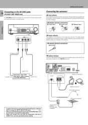
..., S VIDEO OUT video game, digital camera, or portable MD player AUDIO OUT FM outdoor antenna Lead the 75Ω coaxial cable connected to the AV AUX jacks, select AV AUX by using an outdoor antenna. R 75µs AM 10kHz FM 100kHz 50µs AM 9kHz FM 50kHz DEEMPHASIS CHANNEL SPACE ANTENNA FM 75Ω PLAY IN REC OUT PLAY IN MONITOR OUT DVD VIDEO 1 VIDEO 1 B R L A R L C R L Attach to the AV AUX jacks (VR-506/517...
..., S VIDEO OUT video game, digital camera, or portable MD player AUDIO OUT FM outdoor antenna Lead the 75Ω coaxial cable connected to the AV AUX jacks, select AV AUX by using an outdoor antenna. R 75µs AM 10kHz FM 100kHz 50µs AM 9kHz FM 50kHz DEEMPHASIS CHANNEL SPACE ANTENNA FM 75Ω PLAY IN REC OUT PLAY IN MONITOR OUT DVD VIDEO 1 VIDEO 1 B R L A R L C R L Attach to the AV AUX jacks (VR-506/517...

User Manual
Page 15
... Registering setup codes for system operations. Connecting the system control Connecting system control cords after connecting a KENWOOD audio component system lets you operate this unit with the system remote supplied with the receiver. To use a cassette deck (or MD recorder) it must be combined with [XR], [XS], and [XS8] equipment for KENWOOD audio components (VR-506/517/KRF-V6050D/V5550D) • If you own remote controllable KENWOOD audio components that are not system control compatible. Do not make system control connections to this unit switches to the VIDEO2/MONITOR jacks...
... Registering setup codes for system operations. Connecting the system control Connecting system control cords after connecting a KENWOOD audio component system lets you operate this unit with the system remote supplied with the receiver. To use a cassette deck (or MD recorder) it must be combined with [XR], [XS], and [XS8] equipment for KENWOOD audio components (VR-506/517/KRF-V6050D/V5550D) • If you own remote controllable KENWOOD audio components that are not system control compatible. Do not make system control connections to this unit switches to the VIDEO2/MONITOR jacks...

User Manual
Page 18
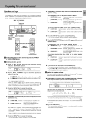
... current channel space setting does not match the setting in the area where the system is lit, the power turns ON when you move from area 1 or area 2 shown in the following table. Front speakers are required for surround playback. Preparations Front speaker Surround speaker Subwoofer Listening position Front speakers : Place to connect a center speaker when using the Dolby 3 Stereo mode. 18 Speaker placement Center speaker Setting up the system Preparing the remote control Loading the batteries 1 Remove the...
... current channel space setting does not match the setting in the area where the system is lit, the power turns ON when you move from area 1 or area 2 shown in the following table. Front speakers are required for surround playback. Preparations Front speaker Surround speaker Subwoofer Listening position Front speakers : Place to connect a center speaker when using the Dolby 3 Stereo mode. 18 Speaker placement Center speaker Setting up the system Preparing the remote control Loading the batteries 1 Remove the...
User Manual
Page 19
... surround speakers are automatically set to step 5. • When subwoofer output sound is OFF. SP A B TI.VOL CLIP MUTE RDS EON PTY TP TA NEWS L CR LFE SW LS S RS FM AUTO SOUND DIGITAL AUTO AM PRO LOGIC S.DIRECT MEMO MHz 3 STEREO MONITOR ST. However, if you change the volume level settings for inputting the distance to the receiver. Surround speaker setting mode to hear sound from SUBW even when it is turned...
... surround speakers are automatically set to step 5. • When subwoofer output sound is OFF. SP A B TI.VOL CLIP MUTE RDS EON PTY TP TA NEWS L CR LFE SW LS S RS FM AUTO SOUND DIGITAL AUTO AM PRO LOGIC S.DIRECT MEMO MHz 3 STEREO MONITOR ST. However, if you change the volume level settings for inputting the distance to the receiver. Surround speaker setting mode to hear sound from SUBW even when it is turned...
User Manual
Page 20
... AUTO SOUND DIGITAL AUTO AM PRO LOGIC S.DIRECT MEMO MHz 3 STEREO MONITOR ST. A+B OFF : No sound from both the speakers connected to input the distance for more than 2 seconds. • The source indication changes to "MD". • To return to the front speakers. Turning on the receiver 1 Turn on the power to the related components. 2 Turn on the rear panel. The CLIP indicator will cause SPEAKER A to be adjusted to any one of audio...
... AUTO SOUND DIGITAL AUTO AM PRO LOGIC S.DIRECT MEMO MHz 3 STEREO MONITOR ST. A+B OFF : No sound from both the speakers connected to input the distance for more than 2 seconds. • The source indication changes to "MD". • To return to the front speakers. Turning on the receiver 1 Turn on the power to the related components. 2 Turn on the rear panel. The CLIP indicator will cause SPEAKER A to be adjusted to any one of audio...

User Manual
Page 21
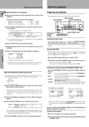
... 6 "DVD/6ch" VR-505 1 "AUX" 2 "TUNER" 3 "CD/DVD" 4 "TAPE" or "MD" 5 "VIDEO1" if VIDEO2/MONITOR is VIDEO2 6 "VIDEO2" 7 "DVD" else if VIDEO2/MONITOR is MONITOR 6 "DVD" VR-517/KRF-V5550D 1 "AUX" 2 "TUNER" 3 "CD/DVD" 4 "TAPE" or "MD" 5 "VIDEO1" if VIDEO2/MONITOR is VIDEO2 6 "VIDEO2" 7 "DVD/6ch" 8 "AV AUX" (VR-517 only) else if VIDEO2/MONITOR is in the PCM stereo and analog stereo modes. The input sources change as appropriate. 9 Adjusting the sound MULTI CONTROL SOURCE DIRECT SOUND Operations SPEAKERS A/B PHONES (SPEAKER/MUTE) VOLUME CONTROL SOUND MULTI CONTROL BASS...
... 6 "DVD/6ch" VR-505 1 "AUX" 2 "TUNER" 3 "CD/DVD" 4 "TAPE" or "MD" 5 "VIDEO1" if VIDEO2/MONITOR is VIDEO2 6 "VIDEO2" 7 "DVD" else if VIDEO2/MONITOR is MONITOR 6 "DVD" VR-517/KRF-V5550D 1 "AUX" 2 "TUNER" 3 "CD/DVD" 4 "TAPE" or "MD" 5 "VIDEO1" if VIDEO2/MONITOR is VIDEO2 6 "VIDEO2" 7 "DVD/6ch" 8 "AV AUX" (VR-517 only) else if VIDEO2/MONITOR is in the PCM stereo and analog stereo modes. The input sources change as appropriate. 9 Adjusting the sound MULTI CONTROL SOURCE DIRECT SOUND Operations SPEAKERS A/B PHONES (SPEAKER/MUTE) VOLUME CONTROL SOUND MULTI CONTROL BASS...
User Manual
Page 22
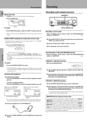
... all of the connected component. 3 Use the VOLUME CONTROL knob (VOLUME keys) to the VIDEO2/ MONITOR jacks, you will be canceled. • If CINEMA EQ. Make sure the SPEAKERS indicators are turned off , you can compare the sound of the double cassette deck. Make sure the SP indicators are turned off . FM AUTO SOUND DIGITAL AUTO AM PRO LOGIC S.DIRECT MEMO MHz 3 STEREO MONITOR ST. By switching the MONITOR key...
... all of the connected component. 3 Use the VOLUME CONTROL knob (VOLUME keys) to the VIDEO2/ MONITOR jacks, you will be canceled. • If CINEMA EQ. Make sure the SPEAKERS indicators are turned off , you can compare the sound of the double cassette deck. Make sure the SP indicators are turned off . FM AUTO SOUND DIGITAL AUTO AM PRO LOGIC S.DIRECT MEMO MHz 3 STEREO MONITOR ST. By switching the MONITOR key...
User Manual
Page 27
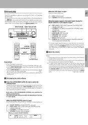
... the DOLBY DIGITAL signal is input: 1 PRO LOGIC: PRO LOGIC surround (The PRO LOGIC indicator lights up.) 2 3 STEREO: 3-STEREO surround (The 3 STEREO indica tor lights up .) 3 3 STEREO: 3-STEREO surround 4 STEREO: Normal stereo playback When you wish to play The DTS compatible models can be used when playing video, DVD, or LD software bearing the mark. Each press of the receiver. Connect the Dolby Digital compatible source component's Dolby Digital format digital audio signal to one of the DIGITAL INPUT jacks on the type of available channels. 3 Adjust the volume...
... the DOLBY DIGITAL signal is input: 1 PRO LOGIC: PRO LOGIC surround (The PRO LOGIC indicator lights up.) 2 3 STEREO: 3-STEREO surround (The 3 STEREO indica tor lights up .) 3 3 STEREO: 3-STEREO surround 4 STEREO: Normal stereo playback When you wish to play The DTS compatible models can be used when playing video, DVD, or LD software bearing the mark. Each press of the receiver. Connect the Dolby Digital compatible source component's Dolby Digital format digital audio signal to one of the DIGITAL INPUT jacks on the type of available channels. 3 Adjust the volume...
User Manual
Page 28
... adjustment) 3 C (center speaker level adjustment) 4 SR (right surround speaker level adjustment) 5 SL (left surround speaker level adjustment) 6 SW (subwoofer level adjustment) 7 INPUT (input level adjustment) 8 NIGHT (midnight mode on/off and speaker system A turns on all other than Dolby Digital such as the input source, it switches off ) ¡ ¡ ) 2 Use the MULTI CONTROL keys to adjust the setting as follows: Note that you press the button, the menu changes as desired. • The adjustment item is displayed for surround sound". ( 1 Select "DVD/6ch" as the input source...
... adjustment) 3 C (center speaker level adjustment) 4 SR (right surround speaker level adjustment) 5 SL (left surround speaker level adjustment) 6 SW (subwoofer level adjustment) 7 INPUT (input level adjustment) 8 NIGHT (midnight mode on/off and speaker system A turns on all other than Dolby Digital such as the input source, it switches off ) ¡ ¡ ) 2 Use the MULTI CONTROL keys to adjust the setting as follows: Note that you press the button, the menu changes as desired. • The adjustment item is displayed for surround sound". ( 1 Select "DVD/6ch" as the input source...

User Manual
Page 30
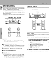
... the setup code. • Example: Press "805" to register a DVD player made by system control cords. Input (DVD) Component Maker Code DVD player KENWOOD 805, 808 Key DVD RC-R0615/R0617 1 Use the input selector keys to select the component you desire. • Pressing the input selector keys also changes the input selector on the receiver. • When you operate your registered TV, VCR, DVD player, Cable tuner, or DSS receiver, go to step 2. • When you operate the CD player...
... the setup code. • Example: Press "805" to register a DVD player made by system control cords. Input (DVD) Component Maker Code DVD player KENWOOD 805, 808 Key DVD RC-R0615/R0617 1 Use the input selector keys to select the component you desire. • Pressing the input selector keys also changes the input selector on the receiver. • When you operate your registered TV, VCR, DVD player, Cable tuner, or DSS receiver, go to step 2. • When you operate the CD player...
User Manual
Page 39
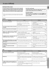
...; Set the SPEAKERS switch(es) to ON. ) The standby indicator blinks and sound is • Speaker cords are set to "Connecting the speakers". & • Select a surround mode. • Adjust the speaker levels using the test tone. ( A humming noise is generated when the PHONO input selector is selected. • The audio cord from the wall outlet, then plug it back in when it left the factory. 39 For U.S.A. When playing a Dolby Digital source signal using a DVD player, the sound is...
...; Set the SPEAKERS switch(es) to ON. ) The standby indicator blinks and sound is • Speaker cords are set to "Connecting the speakers". & • Select a surround mode. • Adjust the speaker levels using the test tone. ( A humming noise is generated when the PHONO input selector is selected. • The audio cord from the wall outlet, then plug it back in when it left the factory. 39 For U.S.A. When playing a Dolby Digital source signal using a DVD player, the sound is...
User Manual
Page 40
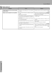
... activate the operation mode for the respective • Register a setup code at for the component you wish to control. • The microprocessor of difficulty Remote control unit 40 Symptom Certain inputs cannot be selected using the remote control. Additional Information input(s). º • The remote control is set to the operation mode for the component you want to play a tape which is not possible. trollable range. • Connect properly referring to "Setting up the system...
... activate the operation mode for the respective • Register a setup code at for the component you wish to control. • The microprocessor of difficulty Remote control unit 40 Symptom Certain inputs cannot be selected using the remote control. Additional Information input(s). º • The remote control is set to the operation mode for the component you want to play a tape which is not possible. trollable range. • Connect properly referring to "Setting up the system...


