

User Manual
Page 3
... discs and tapes 5 System connection (XD-951/XD-A900 6 Connection of the System Accessories 6 System connection (XD-A700 8 Connection of the System Accessories 8 Connection of the surround speakers 10 Connection of Options (Optional Parts 11 Controls and indicators 12 Main Unit 12 Display 14 Remote control Unit 15 Operation of remote control unit 16 CHANNEL SPACE setting 16 Basic section Let's put out some sound 18 Basic use method 18 Playback of CD 20 Playback of tape 22 Searching for the desired music program...
... discs and tapes 5 System connection (XD-951/XD-A900 6 Connection of the System Accessories 6 System connection (XD-A700 8 Connection of the System Accessories 8 Connection of the surround speakers 10 Connection of Options (Optional Parts 11 Controls and indicators 12 Main Unit 12 Display 14 Remote control Unit 15 Operation of remote control unit 16 CHANNEL SPACE setting 16 Basic section Let's put out some sound 18 Basic use method 18 Playback of CD 20 Playback of tape 22 Searching for the desired music program...

User Manual
Page 4
... sub woofer (XD-951/XD-A900 only) ( Each 3-way speaker incorporates an additional sub woofer to reproduce heavy bass more powerfully than conventional system speakers. 3D Wide FL display $ The easy to see graphical display features a large spectrum analyzer. MODE /DEMO To switch over the demonstration: Turn the unit OFF (STANDBY mode) and press the key. If your unit is ON, stations with weak radio waves are muted and their sound...
... sub woofer (XD-951/XD-A900 only) ( Each 3-way speaker incorporates an additional sub woofer to reproduce heavy bass more powerfully than conventional system speakers. 3D Wide FL display $ The easy to see graphical display features a large spectrum analyzer. MODE /DEMO To switch over the demonstration: Turn the unit OFF (STANDBY mode) and press the key. If your unit is ON, stations with weak radio waves are muted and their sound...

User Manual
Page 5
... power XD-951/A900/A700 (En) Handling Hold compact discs so that you do not touch the playing surface. For A side For B side To store cassette tapes Do not store the tapes in its case. It is subject to prevent the recorded contents from the CD player and store it from being erased or recorded on accidentally. Never play only the audio...
... power XD-951/A900/A700 (En) Handling Hold compact discs so that you do not touch the playing surface. For A side For B side To store cassette tapes Do not store the tapes in its case. It is subject to prevent the recorded contents from the CD player and store it from being erased or recorded on accidentally. Never play only the audio...

User Manual
Page 7
In case an associated system component is connected, also read the instruction manual of musical instruments, etc. speaker cords. 3. polarity are inverted, the sound will be produced or noise may result. take. 4. rear panel: 10 cm FM indoor antenna The accessory antenna is variable depending on the model and marketing destination area. 3 Speaker Unit 1 Twist Before connecting the Front Notes Speakers Stick the supplied front speaker cushions to the bottom...
In case an associated system component is connected, also read the instruction manual of musical instruments, etc. speaker cords. 3. polarity are inverted, the sound will be produced or noise may result. take. 4. rear panel: 10 cm FM indoor antenna The accessory antenna is variable depending on the model and marketing destination area. 3 Speaker Unit 1 Twist Before connecting the Front Notes Speakers Stick the supplied front speaker cushions to the bottom...

User Manual
Page 10
... System connection (XD-951/XD-A900/XD-A700) XD-951/A900/A700 (En) Connection of the surround speakers Do not plug the power cord into the power outlet until all of currently available Dolby Surround home video software. MAX. AUX INPUT LEVEL +- This unit is available for CRS-N551) +- Center speaker Subwoofer* Front Speaker Surround speakers (monaural signal) * Optional in this mode. Center speaker Subwoofer* Front Speaker * Optional in this mode. Attach the provided mounting hardware onto the rear panel of the screw projected by hooking...
... System connection (XD-951/XD-A900/XD-A700) XD-951/A900/A700 (En) Connection of the surround speakers Do not plug the power cord into the power outlet until all of currently available Dolby Surround home video software. MAX. AUX INPUT LEVEL +- This unit is available for CRS-N551) +- Center speaker Subwoofer* Front Speaker Surround speakers (monaural signal) * Optional in this mode. Center speaker Subwoofer* Front Speaker * Optional in this mode. Attach the provided mounting hardware onto the rear panel of the screw projected by hooking...

User Manual
Page 11
...;) L SURROUND SPEAKERS (12-16Ω) R SUPER WOOFER PRE OUT Super woofer Extremely low sound is not used. 4. This can be used. Application section Knowledge sections Audio input Audio output Video deck Monitor TV Notes 1. and Canada) DIGITAL OUT jack (OPTICAL) Optical-fiber cable DIGITAL OUT OPTICAL If necessary, remove the cap and plug the optical-fiber cable (optional). Never band or bundle the optical-fiber cable. FM outdoor antenna Lead the 75Ω coaxial cable connected...
...;) L SURROUND SPEAKERS (12-16Ω) R SUPER WOOFER PRE OUT Super woofer Extremely low sound is not used. 4. This can be used. Application section Knowledge sections Audio input Audio output Video deck Monitor TV Notes 1. and Canada) DIGITAL OUT jack (OPTICAL) Optical-fiber cable DIGITAL OUT OPTICAL If necessary, remove the cap and plug the optical-fiber cable (optional). Never band or bundle the optical-fiber cable. FM outdoor antenna Lead the 75Ω coaxial cable connected...

User Manual
Page 12
... external view is variable depending on the model and marketing destination area. BASS SOUND DISPLAY TIMER MODE /DEMO LISTEN MODE 1- and Canada) 8 90! @ # $ %^& 1 2 3 4 5 6 7 ¡ ™ £ • ª º MINI HiFi COMPONENT SYSTEM SRS ( ) UP VOLUME CONTROL ON/STANDBY 3 STEREO PRO LOGIC EX. MIN MAX SET DOWN MULTI CONTROL SRS 3D CD PGM DUBBING ENTER TUNING BAND AUTO PHONES 0 PUSH OPEN 0 PUSH OPEN PLAY REC/ PLAY DISC 1 REV.MODE DOLBY NR 1 2 7 DISC 2 DISC SKIP DISC 3 REC/ARM 3 ¡ A/B 0 4¢ 76 * ( ) Basic section...
... external view is variable depending on the model and marketing destination area. BASS SOUND DISPLAY TIMER MODE /DEMO LISTEN MODE 1- and Canada) 8 90! @ # $ %^& 1 2 3 4 5 6 7 ¡ ™ £ • ª º MINI HiFi COMPONENT SYSTEM SRS ( ) UP VOLUME CONTROL ON/STANDBY 3 STEREO PRO LOGIC EX. MIN MAX SET DOWN MULTI CONTROL SRS 3D CD PGM DUBBING ENTER TUNING BAND AUTO PHONES 0 PUSH OPEN 0 PUSH OPEN PLAY REC/ PLAY DISC 1 REV.MODE DOLBY NR 1 2 7 DISC 2 DISC SKIP DISC 3 REC/ARM 3 ¡ A/B 0 4¢ 76 * ( ) Basic section...
User Manual
Page 13
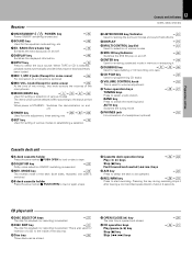
... operated. ¶REC/ARM key ª⁄ Press to start recording. When TAPE or CD is selected, playback starts automatically provided that time. When power is STANDBY: Switches the demonstration on and off. 9 TIMER key YUI Used for time adjustment, timer setting, etc. 0 SET key ( Used for setting of various modes or establishing a selection. 13 Controls and indicators XD-951/A900/A700 (En) !LISTEN MODE key/Indicator Q Used for setting the surround modes and sound field effects. @ DISPLAY $ #MULTI CONTROL...
... operated. ¶REC/ARM key ª⁄ Press to start recording. When TAPE or CD is selected, playback starts automatically provided that time. When power is STANDBY: Switches the demonstration on and off. 9 TIMER key YUI Used for time adjustment, timer setting, etc. 0 SET key ( Used for setting of various modes or establishing a selection. 13 Controls and indicators XD-951/A900/A700 (En) !LISTEN MODE key/Indicator Q Used for setting the surround modes and sound field effects. @ DISPLAY $ #MULTI CONTROL...

User Manual
Page 14
... tape transport direction. 7CD player indicators This section displays the CD playback and pause mode information as well as the disc number being played. 8Track number indicators Indicates the CD track number being played. 9Spectrum analyzer display 0Running indicator This indicator rotates according to the operation modes during the setting of an item using the jog dial. & Knowledge sections Guideline Blinks during operation of the tuner operations and applied CD operations. 3 Character information display Displays the input...
... tape transport direction. 7CD player indicators This section displays the CD playback and pause mode information as well as the disc number being played. 8Track number indicators Indicates the CD track number being played. 9Spectrum analyzer display 0Running indicator This indicator rotates according to the operation modes during the setting of an item using the jog dial. & Knowledge sections Guideline Blinks during operation of the tuner operations and applied CD operations. 3 Character information display Displays the input...

User Manual
Page 15
... & PTY A/B TAPE CD BAND TUNING P.CALL SET MUTE INPUT MENU ENTER VOLUME REMOTE CONTROL UNIT RC-951R @ # $ % ^ & * ( ) ¡ ™ £ ¢ Europe, U.K. and Russia : RC-951R Other countries : RC-951 Model: See left. POWER 1 2 3 TIME 4 5 6 REPEAT EQ ON/OFF 7 8 9 RANDOM SRS 3D DISC SKIP 0 +10 TEST TONE EX. BASS CENTER DOLBY DOLBY PRO LOGIC 3 STEREO STEREO SURROUND TA/NEWS/ INFO. key ‡ The display contents are selected using keys 8. 0ENTER key ( !SET key ( @TIME key...
... & PTY A/B TAPE CD BAND TUNING P.CALL SET MUTE INPUT MENU ENTER VOLUME REMOTE CONTROL UNIT RC-951R @ # $ % ^ & * ( ) ¡ ™ £ ¢ Europe, U.K. and Russia : RC-951R Other countries : RC-951 Model: See left. POWER 1 2 3 TIME 4 5 6 REPEAT EQ ON/OFF 7 8 9 RANDOM SRS 3D DISC SKIP 0 +10 TEST TONE EX. BASS CENTER DOLBY DOLBY PRO LOGIC 3 STEREO STEREO SURROUND TA/NEWS/ INFO. key ‡ The display contents are selected using keys 8. 0ENTER key ( !SET key ( @TIME key...

User Manual
Page 16
... more between radio channels has been set to the one that prevails in the area to be displayed in some areas. To turn power ON. The system enters the standby mode in which the system is incident to the following table. Remote sensor 6m 30˚ 30˚ Operating range (approx.) Notes 1. When the remote controllable distance becomes short, replace both of the batteries with your...
... more between radio channels has been set to the one that prevails in the area to be displayed in some areas. To turn power ON. The system enters the standby mode in which the system is incident to the following table. Remote sensor 6m 30˚ 30˚ Operating range (approx.) Notes 1. When the remote controllable distance becomes short, replace both of the batteries with your...

User Manual
Page 18
... the component connected to read the instruction manual of the tuner. Selecting the desired output 1 TUNER (Radio) § 2 CD ) 3 TAPE ™ 4 AUX (External input) ! ÷ When you select the AUX input, be switched OFF. ÷ The display part becomes dark when the power is selected, playback will start when a disc or a tape already has been inserted into the PHONES jack. ÷ The sounds from all speakers are cut off. 1 ON/STANDBY INPUT 2 UP VOLUME CONTROL 1. Volume adjustment DOWN 3 ÷ Quick turning produces a larger change...
... the component connected to read the instruction manual of the tuner. Selecting the desired output 1 TUNER (Radio) § 2 CD ) 3 TAPE ™ 4 AUX (External input) ! ÷ When you select the AUX input, be switched OFF. ÷ The display part becomes dark when the power is selected, playback will start when a disc or a tape already has been inserted into the PHONES jack. ÷ The sounds from all speakers are cut off. 1 ON/STANDBY INPUT 2 UP VOLUME CONTROL 1. Volume adjustment DOWN 3 ÷ Quick turning produces a larger change...

User Manual
Page 19
... the MODE/DEMO key. CD 01 0 00 123 Volume display VOL 5 7 123 AUTO POWER SAVE function When the power is ON and neither recording nor playback is executed for the XD-A700) XD-951/A900/A700 (En) Adjust the sub woofer level according to the category of current is switched off alternately. ÷ The EX.BASS is controlled. MULTI CONTROL SET SLEEP TIME SET O.T.T. ON/OFF PROG. 1 PROG. 2 AUTO POWER SAVE 3 Select...
... the MODE/DEMO key. CD 01 0 00 123 Volume display VOL 5 7 123 AUTO POWER SAVE function When the power is ON and neither recording nor playback is executed for the XD-A700) XD-951/A900/A700 (En) Adjust the sub woofer level according to the category of current is switched off alternately. ÷ The EX.BASS is controlled. MULTI CONTROL SET SLEEP TIME SET O.T.T. ON/OFF PROG. 1 PROG. 2 AUTO POWER SAVE 3 Select...

User Manual
Page 47
... section Knowledge sections Indicates the center L--y--R Indicates the balance setting Input level adjustment : Rear panel AUX INPUT LEVEL MIN. AUX INPUT LEVEL MIN. Select the sound field mode according to the AUX terminal. Preparation section Basic section Balance adjustment : 1 Press the MODE/DEMO key. Please select the equalizer as required when the volume from external equipment is displayed. ENTER The left and right volume. SRS LEVEL S.W. (Except for the...
... section Knowledge sections Indicates the center L--y--R Indicates the balance setting Input level adjustment : Rear panel AUX INPUT LEVEL MIN. AUX INPUT LEVEL MIN. Select the sound field mode according to the AUX terminal. Preparation section Basic section Balance adjustment : 1 Press the MODE/DEMO key. Please select the equalizer as required when the volume from external equipment is displayed. ENTER The left and right volume. SRS LEVEL S.W. (Except for the...

User Manual
Page 51
... time setting consists of the sound output from the surround speakers with respect to that output from the front speakers. PHANTOM When the center speaker is medium- When the center speaker is not used. 51 Effective Sound Adjustment DOLBY PRO LOGIC surround adjustment XD-951/A900/A700 (En) When video (LD) software carrying mark is closer to the front speakers 20 mS ...... When the listening position is played, this difference in timing of adjusting this mode...
... time setting consists of the sound output from the surround speakers with respect to that output from the front speakers. PHANTOM When the center speaker is medium- When the center speaker is not used. 51 Effective Sound Adjustment DOLBY PRO LOGIC surround adjustment XD-951/A900/A700 (En) When video (LD) software carrying mark is closer to the front speakers 20 mS ...... When the listening position is played, this difference in timing of adjusting this mode...

User Manual
Page 53
... DOLBY 3 STEREO STEREO DSP NORMAL When the center speaker is medium- WIDEBAND ......... or large-sized speaker. RETURN Returns to step 2. ÷ If you are to be adjusted in place of pressing the "@ #" key of the remote control unit. | Scrolled display (DOLBY 3 STEREO) DOLBY 3 sT The center mode display scrolls. TEST L The display and test tone output speaker are switched auto- Basic section Application section Knowledge sections DOLBY 3 STEREO play Use the VOLUME keys of "DOLBY PRO LOGIC surround adjustment...
... DOLBY 3 STEREO STEREO DSP NORMAL When the center speaker is medium- WIDEBAND ......... or large-sized speaker. RETURN Returns to step 2. ÷ If you are to be adjusted in place of pressing the "@ #" key of the remote control unit. | Scrolled display (DOLBY 3 STEREO) DOLBY 3 sT The center mode display scrolls. TEST L The display and test tone output speaker are switched auto- Basic section Application section Knowledge sections DOLBY 3 STEREO play Use the VOLUME keys of "DOLBY PRO LOGIC surround adjustment...

User Manual
Page 58
....) Set a tape into deck B. ON/OFF PROG.1 ...... lights. ÷ If a program No. Adjust the clock before setting the timer. ing. • Preparation section Application section Select the disc to be set and selected to the AUX jacks. ÷ For recording Make prepara- and press the SET key. UP VOLUME CONTROL DOWN 3 Press the TIMER key. ÷ When the timer function is used every day) are available. MULTI CONTROL SET SLEEP TIME SET O.T.T. tions...
....) Set a tape into deck B. ON/OFF PROG.1 ...... lights. ÷ If a program No. Adjust the clock before setting the timer. ing. • Preparation section Application section Select the disc to be set and selected to the AUX jacks. ÷ For recording Make prepara- and press the SET key. UP VOLUME CONTROL DOWN 3 Press the TIMER key. ÷ When the timer function is used every day) are available. MULTI CONTROL SET SLEEP TIME SET O.T.T. tions...
User Manual
Page 59
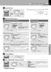
... timer playback 1 Select the mode. MULTI CONTROL Select "TIMER REC". Select the source to be played. ON/OFF" and press the SET key. TIMER PLAY TIMER REC AI PLAY RETURN SET Enter it . 6 Enter the OFF time. 1 MULTI CONTROL 59 Adjust the clock before setting the timer. ENTER MULTI CONTROL TUNER (Radio) CD TAPE AUX (External input) RETURN Enter it . MULTI CONTROL Select the preset station No. TIMER Knowledge sections 9 Select "PROG. TUNER (Radio) AUX (External input) RETURN ENTER Enter it . 2 Select the input source. Timer operation XD-951...
... timer playback 1 Select the mode. MULTI CONTROL Select "TIMER REC". Select the source to be played. ON/OFF" and press the SET key. TIMER PLAY TIMER REC AI PLAY RETURN SET Enter it . 6 Enter the OFF time. 1 MULTI CONTROL 59 Adjust the clock before setting the timer. ENTER MULTI CONTROL TUNER (Radio) CD TAPE AUX (External input) RETURN Enter it . MULTI CONTROL Select the preset station No. TIMER Knowledge sections 9 Select "PROG. TUNER (Radio) AUX (External input) RETURN ENTER Enter it . 2 Select the input source. Timer operation XD-951...

User Manual
Page 61
... carried from power outlet Amplifier POWER status (ON or OFF) Input selection Volume control value Balance level Equalizer's manual memory created by the user SRS 3D level Tuner unit Receiving band Frequency Preset stations Program timer setting contents Cassette deck unit Transport direction DOLBY NR Reverse mode When your unit needs to be repaired, bring the entire set When the front panel or case becomes dirty, wipe with the SOUND RETRIEVAL SYSTEM. for...
... carried from power outlet Amplifier POWER status (ON or OFF) Input selection Volume control value Balance level Equalizer's manual memory created by the user SRS 3D level Tuner unit Receiving band Frequency Preset stations Program timer setting contents Cassette deck unit Transport direction DOLBY NR Reverse mode When your unit needs to be repaired, bring the entire set When the front panel or case becomes dirty, wipe with the SOUND RETRIEVAL SYSTEM. for...

User Manual
Page 62
... weak radio waves are exhausted. ÷ The remote control is ON or due to MIN. Sound is activated. The clock display shows ÷ There was a power failure. ÷ The power cord was not set is installed near the system. ÷ Install the outdoor antenna in the TUNER mode. ÷ Even when DEMO is ON, stations with new batteries. ^ ÷ Operate the unit inside the remote control- ^ lable range. ÷ Set a tape or CD in the component to play...
... weak radio waves are exhausted. ÷ The remote control is ON or due to MIN. Sound is activated. The clock display shows ÷ There was a power failure. ÷ The power cord was not set is installed near the system. ÷ Install the outdoor antenna in the TUNER mode. ÷ Even when DEMO is ON, stations with new batteries. ^ ÷ Operate the unit inside the remote control- ^ lable range. ÷ Set a tape or CD in the component to play...


