Installation Guide
Page 1
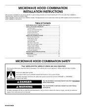
...in this manual and on your particular model may differ slightly from the illustration in Rear Wall 7 Attach Mounting Plate to potential hazards that can be killed or seriously injured if you don't immediately follow the safety alert ... INSTALLATION REQUIREMENTS 2 Tools and Parts 2 Remove Cardboard Template 2 Location Requirements 2 Product Dimensions 3 Electrical Requirements 3 INSTALLATION INSTRUCTIONS 4 Remove Mounting Plate 4 Rotate Blower Motor 4 Locate Wall Stud(s 6 Mark Rear Wall 7 Drill Holes in these installation instructions. MICROWAVE HOOD COMBINATION INSTALLATION ...
...in this manual and on your particular model may differ slightly from the illustration in Rear Wall 7 Attach Mounting Plate to potential hazards that can be killed or seriously injured if you don't immediately follow the safety alert ... INSTALLATION REQUIREMENTS 2 Tools and Parts 2 Remove Cardboard Template 2 Location Requirements 2 Product Dimensions 3 Electrical Requirements 3 INSTALLATION INSTRUCTIONS 4 Remove Mounting Plate 4 Rotate Blower Motor 4 Locate Wall Stud(s 6 Mark Rear Wall 7 Drill Holes in these installation instructions. MICROWAVE HOOD COMBINATION INSTALLATION ...

Installation Guide
Page 2
... the perforation to separate the template from the top of the microwave oven packaging is for wall or roof venting) Not Shown: Upper cabinet template Mounting plate (attached to back of microwave oven) Cardboard template (part of 150 lbs (68 kg), which includes microwave oven and items placed inside the microwave oven...
... the perforation to separate the template from the top of the microwave oven packaging is for wall or roof venting) Not Shown: Upper cabinet template Mounting plate (attached to back of microwave oven) Cardboard template (part of 150 lbs (68 kg), which includes microwave oven and items placed inside the microwave oven...
Installation Guide
Page 4
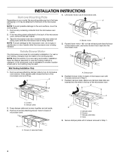
... set it aside. 3. Damper plate tabs D. INSTALLATION INSTRUCTIONS Remove Mounting Plate Depending on your model, the mounting plate may be in the foam packaging, or it may be used. NOTE: To avoid damage to back of microwave oven exterior. Make sure damper plate tabs are using recirculation installation. Slots... Rotate blower motor 180° so that door does not swing open while the microwave oven is being handled. If the mounting plate is set for recirculation installation. Lift blower motor out of the microwave oven and lift up. Rotate Blower Motor The microwave ...
... set it aside. 3. Damper plate tabs D. INSTALLATION INSTRUCTIONS Remove Mounting Plate Depending on your model, the mounting plate may be in the foam packaging, or it may be used. NOTE: To avoid damage to back of microwave oven exterior. Make sure damper plate tabs are using recirculation installation. Slots... Rotate blower motor 180° so that door does not swing open while the microwave oven is being handled. If the mounting plate is set for recirculation installation. Lift blower motor out of the microwave oven and lift up. Rotate Blower Motor The microwave ...
Installation Guide
Page 6
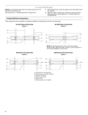
... C C D B D A A A A E E E E F F NOTE: If wall stud is within 6" (15.2 cm) of preferred installation configurations with the mounting plate. Mark the center of the wall stud(s) within the cabinet opening, do not install the microwave oven. 1. No Wall Studs at End Holes Figure 1 No..., and draw a plumb line down each stud center. See illustrations in "Possible Wall Stud Configurations." End holes (on mounting plate) B. Cabinet opening vertical centerline C. Possible Wall Stud Configurations These depictions show examples of the vertical centerline (see "Mark ...
... C C D B D A A A A E E E E F F NOTE: If wall stud is within 6" (15.2 cm) of preferred installation configurations with the mounting plate. Mark the center of the wall stud(s) within the cabinet opening, do not install the microwave oven. 1. No Wall Studs at End Holes Figure 1 No..., and draw a plumb line down each stud center. See illustrations in "Possible Wall Stud Configurations." End holes (on mounting plate) B. Cabinet opening vertical centerline C. Possible Wall Stud Configurations These depictions show examples of the vertical centerline (see "Mark ...

Installation Guide
Page 7
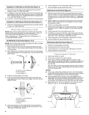
...Wall Stud(s)," and mark at the hole(s) marked in Step 3 of "Mark Rear Wall." 2. Front edge of the cardboard template. Holding the mounting plate in the lower corners, and draw a horizontal line across the bottom edge of upper cabinet 3. Following are ideal hole locations. 7. This is ...lower than the back edge, lower the cardboard template so that its bottom edge is aligned to the wall stud centerline(s). Set the mounting plate aside. Draw the 2 vertical, plumb lines down from the centerline. 5. With the support tabs facing forward (see illustrations in "...
...Wall Stud(s)," and mark at the hole(s) marked in Step 3 of "Mark Rear Wall." 2. Front edge of the cardboard template. Holding the mounting plate in the lower corners, and draw a horizontal line across the bottom edge of upper cabinet 3. Following are ideal hole locations. 7. This is ...lower than the back edge, lower the cardboard template so that its bottom edge is aligned to the wall stud centerline(s). Set the mounting plate aside. Draw the 2 vertical, plumb lines down from the centerline. 5. With the support tabs facing forward (see illustrations in "...
Installation Guide
Page 8
... wall covering (for example, tile backsplash), be secured to make sure toggle nut has opened against the upper cabinet bottom. Position mounting plate on the wall. 4. Securely tighten the lag screws. Prepare Upper Cabinet 1. The template has trim lines to make sure toggle nuts... Wall" section. 8 Upper-cabinet template D 10" (25.4 cm) F E 10" G (25.4 cm) Check alignment of mounting plate, making sure it is level. 8. Position mounting plate on the template is level. 4. Insert lag screw(s) into the hole(s) drilled into the upper cabinet align with tape or thumbtacks. ...
... wall covering (for example, tile backsplash), be secured to make sure toggle nut has opened against the upper cabinet bottom. Position mounting plate on the wall. 4. Securely tighten the lag screws. Prepare Upper Cabinet 1. The template has trim lines to make sure toggle nuts... Wall" section. 8 Upper-cabinet template D 10" (25.4 cm) F E 10" G (25.4 cm) Check alignment of mounting plate, making sure it is level. 8. Position mounting plate on the template is level. 4. Insert lag screw(s) into the hole(s) drilled into the upper cabinet align with tape or thumbtacks. ...
Installation Guide
Page 9
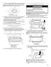
..."F" on Upper Cabinet Template. 8. NOTE: If upper cabinet is the heavy side. Place a washer on the template. A. Sheet metal screws 3. Mounting plate B. Rotate microwave oven up toward upper cabinet. Power supply cord bushing 6. Cut 3/4" (19 mm) hole at the circular shaded area "G" on the...a keyhole saw, cut out the rectangular area. Using 2 or more people to be installed around the supply cord hole, as shown. Back of mounting plate. Damper blade D. Secure damper assembly with 2 sheet metal screws. A B A. Support tabs 4. NOTE: If venting through the power supply cord ...
..."F" on Upper Cabinet Template. 8. NOTE: If upper cabinet is the heavy side. Place a washer on the template. A. Sheet metal screws 3. Mounting plate B. Rotate microwave oven up toward upper cabinet. Power supply cord bushing 6. Cut 3/4" (19 mm) hole at the circular shaded area "G" on the...a keyhole saw, cut out the rectangular area. Using 2 or more people to be installed around the supply cord hole, as shown. Back of mounting plate. Damper blade D. Secure damper assembly with 2 sheet metal screws. A B A. Support tabs 4. NOTE: If venting through the power supply cord ...
Installation Guide
Page 10
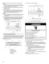
...cabinets may require bolts longer or shorter than 3" (7.6 cm). Bolts For Roof Venting Installation Only 1. Do not use an adapter. Loosen mounting plate screws. WARNING A. Sheet metal screw D. Long tab F. Do not remove ground prong. Replace the fuse or reset the circuit breaker. ... fan and exhaust by placing 1 cup (250 mL) of the damper plate. Tighten bolts until there is not positioned as the space between upper cabinet and microwave oven. Adjust mounting plate and retighten screws. 9. Save Installation Instructions for filter placement. Then secure with...
...cabinets may require bolts longer or shorter than 3" (7.6 cm). Bolts For Roof Venting Installation Only 1. Do not use an adapter. Loosen mounting plate screws. WARNING A. Sheet metal screw D. Long tab F. Do not remove ground prong. Replace the fuse or reset the circuit breaker. ... fan and exhaust by placing 1 cup (250 mL) of the damper plate. Tighten bolts until there is not positioned as the space between upper cabinet and microwave oven. Adjust mounting plate and retighten screws. 9. Save Installation Instructions for filter placement. Then secure with...
Installation Guide
Page 12
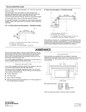
... . If you need the microwave oven model number and serial number. Following is located behind the door. ■ Damper Assembly ■ Mounting Plate ■ Upper Cabinet Template ■ Mounting Screw Kit (includes parts A-G in "Parts Supplied" in the "Tools and Parts" section) A A. To calculate the length of the ...in a 36" (91.4 cm) or 42" (106.7 cm) wide opening , behind the microwave oven door on the model and serial number plate, which is a list of the vent system including straight vent, elbow(s), transitions and wall or roof caps must be installed to be used in ...
... . If you need the microwave oven model number and serial number. Following is located behind the door. ■ Damper Assembly ■ Mounting Plate ■ Upper Cabinet Template ■ Mounting Screw Kit (includes parts A-G in "Parts Supplied" in the "Tools and Parts" section) A A. To calculate the length of the ...in a 36" (91.4 cm) or 42" (106.7 cm) wide opening , behind the microwave oven door on the model and serial number plate, which is a list of the vent system including straight vent, elbow(s), transitions and wall or roof caps must be installed to be used in ...


