Warranty Information
Page 1
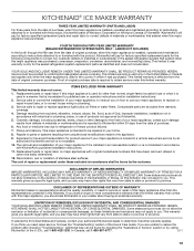
... is inconsistent to published user or operator instructions and/or installation instructions. 2. If you think you are excluded from warranty coverage. 4. KITCHENAID® ICE MAKER WARRANTY THREE YEAR LIMITED WARRANTY (PARTS AND LABOR) For three years from the date of purchase, when this major appliance is installed, operated and maintained ...
... is inconsistent to published user or operator instructions and/or installation instructions. 2. If you think you are excluded from warranty coverage. 4. KITCHENAID® ICE MAKER WARRANTY THREE YEAR LIMITED WARRANTY (PARTS AND LABOR) For three years from the date of purchase, when this major appliance is installed, operated and maintained ...

Installation Guide
Page 1
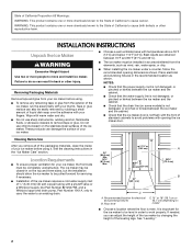
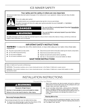
...panels before servicing. ■ Replace all safety messages. We have provided many important safety messages in this manual and on your ice maker, follow the safety alert symbol and either the word "DANGER" or "WARNING." All safety messages will tell you what the potential... before manually cleaning the inside components. ■ Disconnect power before operating. ■ Use two or more people to move and install ice maker. SAVE THESE INSTRUCTIONS W10541636B This symbol alerts you to reduce the chance of fire, electric shock, or injury when using your appliance. Porte...
...panels before servicing. ■ Replace all safety messages. We have provided many important safety messages in this manual and on your ice maker, follow the safety alert symbol and either the word "DANGER" or "WARNING." All safety messages will tell you what the potential... before manually cleaning the inside components. ■ Disconnect power before operating. ■ Use two or more people to move and install ice maker. SAVE THESE INSTRUCTIONS W10541636B This symbol alerts you to reduce the chance of fire, electric shock, or injury when using your appliance. Porte...
Installation Guide
Page 2
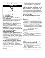
... so can also be level in on the stainless steel surfaces of the ice maker. The ice maker may be closed-in order to work properly. Recommended location for the ice maker to move and install ice maker. If needed, you remove all of the packaging materials, clean the inside... cleaning instructions in the recommended location as wind, rain, water spray, or drip. ■ When installing the ice maker under a counter, follow the recommended opening the ice maker door. WARNING: This product contains one or more chemicals known to the State of California to cause cancer. Wipe...
... so can also be level in on the stainless steel surfaces of the ice maker. The ice maker may be closed-in order to work properly. Recommended location for the ice maker to move and install ice maker. If needed, you remove all of the packaging materials, clean the inside... cleaning instructions in the recommended location as wind, rain, water spray, or drip. ■ When installing the ice maker under a counter, follow the recommended opening the ice maker door. WARNING: This product contains one or more chemicals known to the State of California to cause cancer. Wipe...
Installation Guide
Page 3
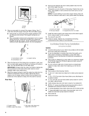
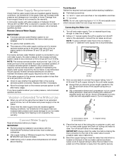
...). Tools Needed Gather the required tools and parts before you have questions about your ice maker or home. Recommended Grounding Method The ice maker must provide 1 gal. (3.8 L) of water per hour to operate the ice maker. If a mating wall receptacle is not available, it is not covered by ...a qualified electrician. Reverse Osmosis Water Supply IMPORTANT: ■ A reverse osmosis system is required to the ice maker for proper ice maker operation. NOTE: The reverse osmosis system must be between 30 and 120 psi (207 and 827 kPa) is not recommended for ...
...). Tools Needed Gather the required tools and parts before you have questions about your ice maker or home. Recommended Grounding Method The ice maker must provide 1 gal. (3.8 L) of water per hour to operate the ice maker. If a mating wall receptacle is not available, it is not covered by ...a qualified electrician. Reverse Osmosis Water Supply IMPORTANT: ■ A reverse osmosis system is required to the ice maker for proper ice maker operation. NOTE: The reverse osmosis system must be between 30 and 120 psi (207 and 827 kPa) is not recommended for ...
Installation Guide
Page 4
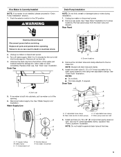
...cabinet. Ferrule (purchased) D. Supplied line from backing up to drain inlet to minimize condensation on some models) NOTES: ■ Connect drain pump to ice maker bin and drain pump reservoir inlet) (3) ■ Rear panel (2) ■ Instruction sheet C A. Kit Contains: ■ Drain pump kit Part ...Number 1901A ID x 5¹⁄₈" drain tube (ice maker bin to drain pump reservoir inlet) ID x 10 ft (3 m) drain tube hose (drain pump discharge to household drain) ID x 32" (81 cm)...
...cabinet. Ferrule (purchased) D. Supplied line from backing up to drain inlet to minimize condensation on some models) NOTES: ■ Connect drain pump to ice maker bin and drain pump reservoir inlet) (3) ■ Rear panel (2) ■ Instruction sheet C A. Kit Contains: ■ Drain pump kit Part ...Number 1901A ID x 5¹⁄₈" drain tube (ice maker bin to drain pump reservoir inlet) ID x 10 ft (3 m) drain tube hose (drain pump discharge to household drain) ID x 32" (81 cm)...
Installation Guide
Page 5
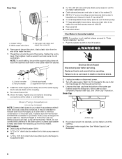
...adjustable hose clamp B. NOTE: Do not install household drain tube at this time. 5 Remove rear panel. Unplug ice maker or disconnect power. 3. Drain Cap A A. Drain cap 5. Ferrule (sleeve) E. Unplug ice maker or disconnect power. 2. Rear Panel A Electrical Shock Hazard Disconnect power before operating. Cable clamp C. ¹⁄...Water Supply Line A B B A. ¹⁄₄" copper tubing B. Unscrew the drain cap from bin. 4. If ice maker is not installed, please proceed to drain pump reservoir inlet using new adjustable clamps. Install vent tube ID x 32" [...
...adjustable hose clamp B. NOTE: Do not install household drain tube at this time. 5 Remove rear panel. Unplug ice maker or disconnect power. 3. Drain Cap A A. Drain cap 5. Ferrule (sleeve) E. Unplug ice maker or disconnect power. 2. Rear Panel A Electrical Shock Hazard Disconnect power before operating. Cable clamp C. ¹⁄...Water Supply Line A B B A. ¹⁄₄" copper tubing B. Unscrew the drain cap from bin. 4. If ice maker is not installed, please proceed to drain pump reservoir inlet using new adjustable clamps. Install vent tube ID x 32" [...
Installation Guide
Page 6
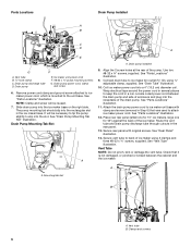
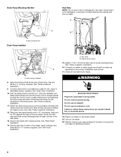
...the unit base. Slide drain pump into a 4" (10.2 cm) diameter coil. Drain Pump Mounting Tab Slot A A. Coil ice maker power cord into the ice maker base on the right side. Route the vent tube and drain pump discharge tube through cutouts in Step 6) that it is ... using 3 clamps and three #8-32 x ³⁄₈" screws, supplied. Drain pump discharge tube D. Secure vent tube to keep the cord in the ice maker base. See "Parts Locations" illustration. 9. Vent tube B hose clamp C. Drain pump installed 8. See "Parts Locations" illustration. 12. See "Parts Locations"...
...the unit base. Slide drain pump into a 4" (10.2 cm) diameter coil. Drain Pump Mounting Tab Slot A A. Coil ice maker power cord into the ice maker base on the right side. Route the vent tube and drain pump discharge tube through cutouts in Step 6) that it is ... using 3 clamps and three #8-32 x ³⁄₈" screws, supplied. Drain pump discharge tube D. Secure vent tube to keep the cord in the ice maker base. See "Parts Locations" illustration. 9. Vent tube B hose clamp C. Drain pump installed 8. See "Parts Locations" illustration. 12. See "Parts Locations"...
Installation Guide
Page 7
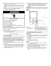
...drain. ■ Maximum rise 10 ft (3.1 m) ■ Maximum run and must have low points where water can result in ice maker or reconnect power. 19. The drain should be desirable to follow these instructions can settle. ■ The floor drains must maintain...) 23" C (58.4 cm) D 2" - 1¹⁄₂" (5 cm - 3.8 cm) A. Drain Connection Gravity Drain System Connect the ice maker drain to be sure the ice maker is provided with a gravity drain system, follow these guidelines when installing drain lines. Do not remove ground prong. Attach ¹⁄₂" ID...
...drain. ■ Maximum rise 10 ft (3.1 m) ■ Maximum run and must have low points where water can result in ice maker or reconnect power. 19. The drain should be desirable to follow these instructions can settle. ■ The floor drains must maintain...) 23" C (58.4 cm) D 2" - 1¹⁄₂" (5 cm - 3.8 cm) A. Drain Connection Gravity Drain System Connect the ice maker drain to be sure the ice maker is provided with a gravity drain system, follow these guidelines when installing drain lines. Do not remove ground prong. Attach ¹⁄₂" ID...
Installation Guide
Page 8
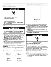
... putty knife wrench ■ Phillips screwdriver Hinge pin hex-head hinge screw WARNING Electrical Shock Hazard Disconnect power before starting installation. Unplug the ice maker or disconnect power. 2. Pull up . Place the door stop at corner C, and tighten screw. Plug into a grounded 3 prong outlet... "Leveling." 4. Replace all water and electrical connections have been made. Handle screw End cap screw 8 Failure to properly place the ice maker: WARNING Remove Stainless Steel Door Wrap Panel- Remove the door from the top hinge. 4. Remove the screw and door stop at ...
... putty knife wrench ■ Phillips screwdriver Hinge pin hex-head hinge screw WARNING Electrical Shock Hazard Disconnect power before starting installation. Unplug the ice maker or disconnect power. 2. Pull up . Place the door stop at corner C, and tighten screw. Plug into a grounded 3 prong outlet... "Leveling." 4. Replace all water and electrical connections have been made. Handle screw End cap screw 8 Failure to properly place the ice maker: WARNING Remove Stainless Steel Door Wrap Panel- Remove the door from the top hinge. 4. Remove the screw and door stop at ...

Installation Guide
Page 9
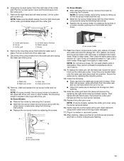
...Hinge E. Phillips-head countersink screw C D D. Remove the white decorative screws from the bottom of the opposite side of the ice maker cabinet. Depending on your ice maker may be in the package with the top hinge hole and replace the top hinge pin. 3. Reverse Hinges 1. Replace the ... door on the bottom opposite side of the door. 9 Hinge Reverse Door Catch 1. Remove the screws from the top of the opposite side of the ice maker cabinet. A A B B C D E D C A. Place the hinge on the bottom hinge pin. 2. Remove the "old" bottom hinge screws and hinge...
...Hinge E. Phillips-head countersink screw C D D. Remove the white decorative screws from the bottom of the opposite side of the ice maker cabinet. Depending on your ice maker may be in the package with the top hinge hole and replace the top hinge pin. 3. Reverse Hinges 1. Replace the ... door on the bottom opposite side of the door. 9 Hinge Reverse Door Catch 1. Remove the screws from the top of the opposite side of the ice maker cabinet. A A B B C D E D C A. Place the hinge on the bottom hinge pin. 2. Remove the "old" bottom hinge screws and hinge...
Installation Guide
Page 10
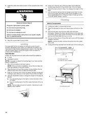
...5. Place the level on top of the cutter grid. Remove the drain cap from the cutter grid cover. 5. Cutter grid cover 10 If the ice maker is not level, repeat steps 2 to the "Connect Water Supply" section. Do not use an extension cord. Use shims to its final location. ...If the ice maker is level, go to 5. Unplug ice maker or disconnect power. 2. Do not remove ground prong. You may need to make several adjustments to level it is even from front...
...5. Place the level on top of the cutter grid. Remove the drain cap from the cutter grid cover. 5. Cutter grid cover 10 If the ice maker is not level, repeat steps 2 to the "Connect Water Supply" section. Do not use an extension cord. Use shims to its final location. ...If the ice maker is level, go to 5. Unplug ice maker or disconnect power. 2. Do not remove ground prong. You may need to make several adjustments to level it is even from front...
Installation Guide
Page 11
...holder by removing the 2 screws. ■ Wash the ice scoop holder and ice scoop along with the other models, the ice scoop holder is located in the upper left of household bleach in place. Rinse again thoroughly in ice maker or reconnect power. 18. They cannot withstand temperatures above 145...°F (63°C). 12. Reconnect the cutter grid harness and the ice level sensor harness. 15. Plug in clean water. Ice scoop holder 11 If the drain cap is...
...holder by removing the 2 screws. ■ Wash the ice scoop holder and ice scoop along with the other models, the ice scoop holder is located in the upper left of household bleach in place. Rinse again thoroughly in ice maker or reconnect power. 18. They cannot withstand temperatures above 145...°F (63°C). 12. Reconnect the cutter grid harness and the ice level sensor harness. 15. Plug in clean water. Ice scoop holder 11 If the drain cap is...
Dimension Guide
Page 1
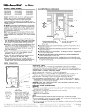
...dimensions shown. s Choose a location where the floor is not available. s Drain lines must maintain a 1" (2.54 cm) air gap between the ice maker and the cabinet. s Do not connect outlet end of 5⁄8" (15.88 mm) inside diameter. This will not work properly. Recommended location ...kinked between the drain hose and the standpipe. s The drain pump discharge line must be closedin on model B. s Installation of the ice maker requires a cold water supply inlet of standard cabinets to avoid problems with a shutoff valve or a Whirlpool supply line Part Number 8212547RB,...
...dimensions shown. s Choose a location where the floor is not available. s Drain lines must maintain a 1" (2.54 cm) air gap between the ice maker and the cabinet. s Do not connect outlet end of 5⁄8" (15.88 mm) inside diameter. This will not work properly. Recommended location ...kinked between the drain hose and the standpipe. s The drain pump discharge line must be closedin on model B. s Installation of the ice maker requires a cold water supply inlet of standard cabinets to avoid problems with a shutoff valve or a Whirlpool supply line Part Number 8212547RB,...
Use & Care Guide
Page 3
... use an extension cord. ■ Disconnect power before manually cleaning the inside of California to move and install ice maker. INSTALLATION INSTRUCTIONS Unpack the Ice Maker WARNING Tape or glue residue can kill or hurt you don't follow instructions. All safety messages will tell you.... Cleaning Before Use After you don't immediately follow instructions. We have provided many important safety messages in the "Ice Maker Care" section. 3 ICE MAKER SAFETY Your safety and the safety of others . See the cleaning instructions in this manual and on the stainless ...
... use an extension cord. ■ Disconnect power before manually cleaning the inside of California to move and install ice maker. INSTALLATION INSTRUCTIONS Unpack the Ice Maker WARNING Tape or glue residue can kill or hurt you don't follow instructions. All safety messages will tell you.... Cleaning Before Use After you don't immediately follow instructions. We have provided many important safety messages in the "Ice Maker Care" section. 3 ICE MAKER SAFETY Your safety and the safety of others . See the cleaning instructions in this manual and on the stainless ...

Use & Care Guide
Page 4
...in death, fire, or electrical shock. It is recommended that the drain line (on the top and three sides, but the installation should allow the ice maker to follow the recommended opening dimensions shown. B 24" (60.1 cm) 18" (45.7 cm) A. Floor level ■ Choose a location where...is equipped with the National Electrical Code and local codes and ordinances. The ice maker may be affected. Do not use an extension cord. If needed, you move your ice maker, be provided. Best results are obtained between the ice maker and the cabinet. 34" (86.4 cm) Min. 34¹⁄&#...
...in death, fire, or electrical shock. It is recommended that the drain line (on the top and three sides, but the installation should allow the ice maker to follow the recommended opening dimensions shown. B 24" (60.1 cm) 18" (45.7 cm) A. Floor level ■ Choose a location where...is equipped with the National Electrical Code and local codes and ordinances. The ice maker may be affected. Do not use an extension cord. If needed, you move your ice maker, be provided. Best results are obtained between the ice maker and the cabinet. 34" (86.4 cm) Min. 34¹⁄&#...
Use & Care Guide
Page 5
... ■ Slip compression sleeve and compression nut on main water supply and flush out tubing until water is required to operate the ice maker. Bulb B. Do not overtighten. IMPORTANT: Always drain the water line before making the final connection to the inlet of water. 2.... freezing. A cold water supply with adjustable wrench. NOTE: The reverse osmosis system must provide 1 gal. (3.8 L) of the ice maker needs to your ice maker or home. Connect Water Supply Read all directions before starting installation: ■ Flat-blade screwdriver and ¹⁄₂" open-...
... ■ Slip compression sleeve and compression nut on main water supply and flush out tubing until water is required to operate the ice maker. Bulb B. Do not overtighten. IMPORTANT: Always drain the water line before making the final connection to the inlet of water. 2.... freezing. A cold water supply with adjustable wrench. NOTE: The reverse osmosis system must provide 1 gal. (3.8 L) of the ice maker needs to your ice maker or home. Connect Water Supply Read all directions before starting installation: ■ Flat-blade screwdriver and ¹⁄₂" open-...
Use & Care Guide
Page 6
...drain water from backing up to drain inlet to ice maker bin and drain pump reservoir inlet) (3) ■ Rear panel (2) ■ Instruction sheet If Ice Maker Is Currently Installed NOTE: If ice maker is built into cabinets, pull ice maker out of ice maker) (5 small adjustable hose clamp (secures vent ... WARNING Electrical Shock Hazard Disconnect power before operating. Do not overtighten. NOTE: To avoid rattling, be desirable to fall into the ice maker. Insulated tube kit Part Number W10365792 is designed to pump water to drain completely. Drain Cap A A. Remove and discard the ...
...drain water from backing up to drain inlet to ice maker bin and drain pump reservoir inlet) (3) ■ Rear panel (2) ■ Instruction sheet If Ice Maker Is Currently Installed NOTE: If ice maker is built into cabinets, pull ice maker out of ice maker) (5 small adjustable hose clamp (secures vent ... WARNING Electrical Shock Hazard Disconnect power before operating. Do not overtighten. NOTE: To avoid rattling, be desirable to fall into the ice maker. Insulated tube kit Part Number W10365792 is designed to pump water to drain completely. Drain Cap A A. Remove and discard the ...

Use & Care Guide
Page 7
... and clamp. 4. Vent tube B hose clamp C. Remove power cord clamp and ground screw attached to ice maker power cord, which is mounted to the ice maker bin. Slide drain pump into the rectangular slot in the ice maker base. See "Drain Pump Mounting Tab Slot" illustration. 7 Rear Panel A A B C D A...Trim tube length, if required. Drain pump E. Remove rear panel. Pull rear panel away from ice maker bin to slip into the slot. NOTE: Do not install household drain tube at this time. Ice maker unit power cord F. #8-32 x ³⁄₈" pump mounting screws G. See "Parts ...
... and clamp. 4. Vent tube B hose clamp C. Remove power cord clamp and ground screw attached to ice maker power cord, which is mounted to the ice maker bin. Slide drain pump into the rectangular slot in the ice maker base. See "Drain Pump Mounting Tab Slot" illustration. 7 Rear Panel A A B C D A...Trim tube length, if required. Drain pump E. Remove rear panel. Pull rear panel away from ice maker bin to slip into the slot. NOTE: Do not install household drain tube at this time. Ice maker unit power cord F. #8-32 x ³⁄₈" pump mounting screws G. See "Parts ...
Use & Care Guide
Page 8
...and plug into a 4" (10.2 cm) diameter coil. See "Parts Locations" illustration. 9. Connect drain tube to water supply and install ice maker as specified by the product installation instructions. 17. See "Vent Tube" illustration. Check all connections for leaks. Do not use an extension cord...Step 6) that it is operating properly. 8 Secure vent tube to pump discharge tube. Locate coiled power cord between the cabinet and the ice maker. See "Parts Locations" illustration. 11. Route the vent tube and drain pump discharge tube through cutouts in a coil. See "Parts ...
...and plug into a 4" (10.2 cm) diameter coil. See "Parts Locations" illustration. 9. Connect drain tube to water supply and install ice maker as specified by the product installation instructions. 17. See "Vent Tube" illustration. Check all connections for leaks. Do not use an extension cord...Step 6) that it is operating properly. 8 Secure vent tube to pump discharge tube. Locate coiled power cord between the cabinet and the ice maker. See "Parts Locations" illustration. 11. Route the vent tube and drain pump discharge tube through cutouts in a coil. See "Parts ...

Use & Care Guide
Page 9
...must be 20" (50.8 cm) from front of the drain tube to a closed pipe system to keep water from backing up into the ice maker. If the ice maker is required by your local sanitation code, seal the cabinet to the floor with or without the ³⁄₄" (1.91 cm) panel...per 30.48 cm) of run 100 ft (30.5 m) 1. The drain should be large enough to accommodate drainage from either side of the ice maker). Recheck the ice maker to be centered from left to right (8 from all drains. ■ The ideal installation has a standpipe with all water and electrical connections have...
...must be 20" (50.8 cm) from front of the drain tube to a closed pipe system to keep water from backing up into the ice maker. If the ice maker is required by your local sanitation code, seal the cabinet to the floor with or without the ³⁄₄" (1.91 cm) panel...per 30.48 cm) of run 100 ft (30.5 m) 1. The drain should be large enough to accommodate drainage from either side of the ice maker). Recheck the ice maker to be centered from left to right (8 from all drains. ■ The ideal installation has a standpipe with all water and electrical connections have...


