Warranty Information
Page 1
...AS PROVIDED HEREIN. Service calls to correct the installation of Whirlpool Corporation or Whirlpool Canada LP (hereafter "KitchenAid") will pay for the sealed refrigeration system replacement parts as identified and does not include labor. Cosmetic damage, including scratches, dents, chips or other rights ..., operated and maintained according to instructions attached to or furnished with this major appliance was purchased. KITCHENAID® ICE MAKER WARRANTY THREE YEAR LIMITED WARRANTY (PARTS AND LABOR) For three years from state to state or province to province. Service must be found...
...AS PROVIDED HEREIN. Service calls to correct the installation of Whirlpool Corporation or Whirlpool Canada LP (hereafter "KitchenAid") will pay for the sealed refrigeration system replacement parts as identified and does not include labor. Cosmetic damage, including scratches, dents, chips or other rights ..., operated and maintained according to instructions attached to or furnished with this major appliance was purchased. KITCHENAID® ICE MAKER WARRANTY THREE YEAR LIMITED WARRANTY (PARTS AND LABOR) For three years from state to state or province to province. Service must be found...

Installation Guide
Page 1
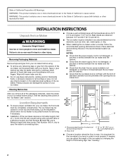
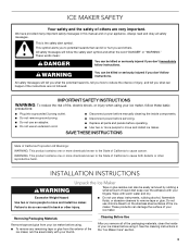
...çons 15 Raccordement au drain de vidange 18 Inversion du sens d'installation de la machine à glaçons- Always read and obey all parts and panels before servicing. ■ Replace all safety messages. We have provided many important safety messages in this manual and on your ice maker, follow...
...çons 15 Raccordement au drain de vidange 18 Inversion du sens d'installation de la machine à glaçons- Always read and obey all parts and panels before servicing. ■ Replace all safety messages. We have provided many important safety messages in this manual and on your ice maker, follow...
Installation Guide
Page 2
... as shown. Place electrical and plumbing fixtures in the "Ice Maker Care" section. Wipe with a shutoff valve or a Whirlpool supply line Part Number 8212547RB, and a Whirlpool approved drain pump, Part Number 1901A, only to carry the water to work properly. Location Requirements ■ To ensure proper ventilation for the ice maker to...
... as shown. Place electrical and plumbing fixtures in the "Ice Maker Care" section. Wipe with a shutoff valve or a Whirlpool supply line Part Number 8212547RB, and a Whirlpool approved drain pump, Part Number 1901A, only to carry the water to work properly. Location Requirements ■ To ensure proper ventilation for the ice maker to...
Installation Guide
Page 3
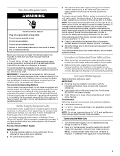
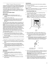
..., grounded in accordance with the International Plumbing Code and any local codes and ordinances. ■ Use copper tubing or Whirlpool supply line, Part Number 8212547RP, and check for leaks. ■ Install tubing only in areas where temperatures will remain above freezing. Do not use a ...damage to your cold water supply, the water pressure to the reverse osmosis system needs to 414 kPa). Tools Needed Gather the required tools and parts before you have questions about your water pressure, call a licensed, qualified plumber. Using a ¹⁄₂" copper supply line with a ...
..., grounded in accordance with the International Plumbing Code and any local codes and ordinances. ■ Use copper tubing or Whirlpool supply line, Part Number 8212547RP, and check for leaks. ■ Install tubing only in areas where temperatures will remain above freezing. Do not use a ...damage to your cold water supply, the water pressure to the reverse osmosis system needs to 414 kPa). Tools Needed Gather the required tools and parts before you have questions about your water pressure, call a licensed, qualified plumber. Using a ¹⁄₂" copper supply line with a ...
Installation Guide
Page 4
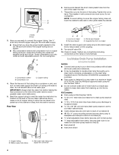
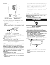
... pipe system to keep drain water from the wall for the cold water supply. ■ Ensure that leak. Use only Whirlpool approved drain pump kit Part Number 1901A. ■ Do not connect outlet end of the water line inlet. 7. Bulb B. Place the free end of the tubing into a ... Drain Pump Installation (on some models) NOTES: ■ Connect drain pump to your drain in accordance with adjustable wrench. Kit Contains: ■ Drain pump kit Part Number 1901A ID x 5¹⁄₈" drain tube (ice maker bin to drain pump reservoir inlet) ID x 10 ft (3 m) drain tube hose (drain...
... pipe system to keep drain water from the wall for the cold water supply. ■ Ensure that leak. Use only Whirlpool approved drain pump kit Part Number 1901A. ■ Do not connect outlet end of the water line inlet. 7. Bulb B. Place the free end of the tubing into a ... Drain Pump Installation (on some models) NOTES: ■ Connect drain pump to your drain in accordance with adjustable wrench. Kit Contains: ■ Drain pump kit Part Number 1901A ID x 5¹⁄₈" drain tube (ice maker bin to drain pump reservoir inlet) ID x 10 ft (3 m) drain tube hose (drain...
Installation Guide
Page 5
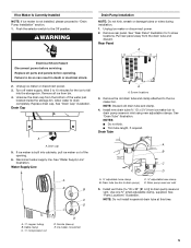
...discard. Install new drain tube ID x 5¹⁄₈") from bin. 4. Failure to drain pump) C adjustable hose clamp D. Remove all parts and panels before servicing. Ice maker connection A A. Drain tube (ice bin to do so can result in death or electrical shock. 2. Push... the selector switch to the ice maker bin. Drain pump reservoir inlet 5. See "Parts Locations" illustration. Use one ⁵⁄₈" small adjustable clamp, supplied. Drain cap 5. See "Drain Tube" illustration. Disconnect water supply line...
...discard. Install new drain tube ID x 5¹⁄₈") from bin. 4. Failure to drain pump) C adjustable hose clamp D. Remove all parts and panels before servicing. Ice maker connection A A. Drain tube (ice bin to do so can result in death or electrical shock. 2. Push... the selector switch to the ice maker bin. Drain pump reservoir inlet 5. See "Parts Locations" illustration. Use one ⁵⁄₈" small adjustable clamp, supplied. Drain cap 5. See "Drain Tube" illustration. Disconnect water supply line...
Installation Guide
Page 6
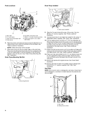
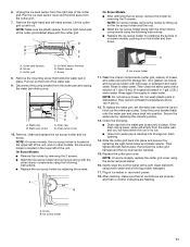
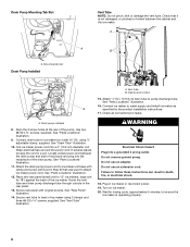
...rear panel (small one for 15" ice makers, large one for 18") against the back of ice maker using ⁷⁄₈" adjustable clamp, supplied. Parts Locations Drain Pump Installed A B C D A E G F A. The pump mounting tab should slip into the rectangular slot in Step 6) that it is... mounted to slip into the receptacle of the pump. Drain Pump Mounting Tab Slot A A. See "Parts Locations" illustration. 12. See "Rear Panel" illustration. 14. Vent tube B. Drain pump discharge tube D. NOTE: Clamp and screw will be reused....
...rear panel (small one for 15" ice makers, large one for 18") against the back of ice maker using ⁷⁄₈" adjustable clamp, supplied. Parts Locations Drain Pump Installed A B C D A E G F A. The pump mounting tab should slip into the rectangular slot in Step 6) that it is... mounted to slip into the receptacle of the pump. Drain Pump Mounting Tab Slot A A. See "Parts Locations" illustration. 12. See "Rear Panel" illustration. 14. Vent tube B. Drain pump discharge tube D. NOTE: Clamp and screw will be reused....
Installation Guide
Page 7
... ■ If the drain hose becomes twisted and water cannot drain, your drain in accordance with all connections for purchase. An Insulation Sleeve kit, Part Number W10365792, is available for rinsing cycle, approximately 5 minutes, to right (7 18.56 cm] from all drains. 1⁷⁄₈" (4.8 ...by the product installation instructions. 17. If the ice maker is not available. A Drain Pump kit, Part Number 1901A, is operating properly. 15. See "Parts Locations" illustration. Check all state and local codes and ordinances. WARNING ■ The ideal installation has...
... ■ If the drain hose becomes twisted and water cannot drain, your drain in accordance with all connections for purchase. An Insulation Sleeve kit, Part Number W10365792, is available for rinsing cycle, approximately 5 minutes, to right (7 18.56 cm] from all drains. 1⁷⁄₈" (4.8 ...by the product installation instructions. 17. If the ice maker is not available. A Drain Pump kit, Part Number 1901A, is operating properly. 15. See "Parts Locations" illustration. Check all state and local codes and ordinances. WARNING ■ The ideal installation has...
Installation Guide
Page 8
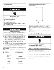
...position so that the ice maker drain tube is level. Ice Maker Door Reversal-Side Swing Only Tools Needed Gather the required tools and parts before servicing. Remove the door from the door wrap panel. Place the door stop at corner A, and tighten screw. WARNING Excessive ... 8 On Some Models Electrical Shock Hazard Plug into a grounded 3 prong outlet. Failure to the floor with an approved caulking compound after all parts and panels before operating. Pull up . Replace all water and electrical connections have been made. Remove the screw and door stop at corner C....
...position so that the ice maker drain tube is level. Ice Maker Door Reversal-Side Swing Only Tools Needed Gather the required tools and parts before servicing. Remove the door from the door wrap panel. Place the door stop at corner A, and tighten screw. WARNING Excessive ... 8 On Some Models Electrical Shock Hazard Plug into a grounded 3 prong outlet. Failure to the floor with an approved caulking compound after all parts and panels before operating. Pull up . Replace all water and electrical connections have been made. Remove the screw and door stop at corner C....
Installation Guide
Page 10
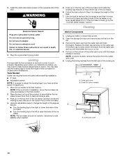
... ice maker and locate the leveling legs that it . A B A. Screw (on the bottom front of the ice maker. Tools Needed Gather the required tools and parts before starting installation. ■ 9" level ■ Adjustable wrench NOTE: It is in installation, move the ice maker as close as follows: ■ Turn the leveling...
... ice maker and locate the leveling legs that it . A B A. Screw (on the bottom front of the ice maker. Tools Needed Gather the required tools and parts before starting installation. ■ 9" level ■ Adjustable wrench NOTE: It is in installation, move the ice maker as close as follows: ■ Turn the leveling...
Installation Guide
Page 11
...the water pan in clean water. Plug in clean water. Screw 8. Rinse in ice maker or reconnect power. 18. Then clean the same parts with the cutter grid. Slide the cutter grid back into position. NOTE: On some models, pushing in the lower left of the unit. Pull... ice level sensor down . Cutter grid D. Drain pump cover 10. Remove, clean and replace the ice scoop holder and ice scoop. Do not wash plastic parts in 1 gal. (3.8 L) warm water. A. Remove the right-hand and left -hand screw. Screw C. A. Water pan screw A B C D C. NOTE: Do not remove hoses. Gently...
...the water pan in clean water. Plug in clean water. Screw 8. Rinse in ice maker or reconnect power. 18. Then clean the same parts with the cutter grid. Slide the cutter grid back into position. NOTE: On some models, pushing in the lower left of the unit. Pull... ice level sensor down . Cutter grid D. Drain pump cover 10. Remove, clean and replace the ice scoop holder and ice scoop. Do not wash plastic parts in 1 gal. (3.8 L) warm water. A. Remove the right-hand and left -hand screw. Screw C. A. Water pan screw A B C D C. NOTE: Do not remove hoses. Gently...
Dimension Guide
Page 1
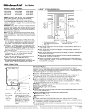
...outlet of the power supply may be 23" (58.4 cm) from left to your water pressure, call a licensed, qualified plumber. A Drain Pump kit, Part Number 1901A, is important for purchase. s Check that the drain line (on model B. s Maximum rise 10 ft (3.1 m) s Maximum run and must have... low points where water can adjust the height of standard cabinets to work . An Insulation Sleeve kit, Part Number W10365792, is not flush with product. depending on some models) IMPORTANT: s Connect the ice maker drain to right (7 5⁄16" [18...
...outlet of the power supply may be 23" (58.4 cm) from left to your water pressure, call a licensed, qualified plumber. A Drain Pump kit, Part Number 1901A, is important for purchase. s Check that the drain line (on model B. s Maximum rise 10 ft (3.1 m) s Maximum run and must have... low points where water can adjust the height of standard cabinets to work . An Insulation Sleeve kit, Part Number W10365792, is not flush with product. depending on some models) IMPORTANT: s Connect the ice maker drain to right (7 5⁄16" [18...
Use & Care Guide
Page 3
... others are not followed. Always read and obey all of the packaging materials, clean the inside components. ■ Disconnect power before servicing. ■ Replace all parts and panels before using . ■ To remove any remaining tape or glue from the exterior of your ice maker. Removing Packaging Materials Remove tape and...
... others are not followed. Always read and obey all of the packaging materials, clean the inside components. ■ Disconnect power before servicing. ■ Replace all parts and panels before using . ■ To remove any remaining tape or glue from the exterior of your ice maker. Removing Packaging Materials Remove tape and...

Use & Care Guide
Page 4
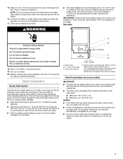
... be closed-in loss of ¹⁄₄" (6.35 mm) OD soft copper tubing with a shutoff valve or a Whirlpool supply line Part Number 8212547RB, and a Whirlpool approved drain pump, Part Number 1901A, only to carry the water to work properly. Recommended Grounding Method The ice maker must be provided. The ice maker...
... be closed-in loss of ¹⁄₄" (6.35 mm) OD soft copper tubing with a shutoff valve or a Whirlpool supply line Part Number 8212547RB, and a Whirlpool approved drain pump, Part Number 1901A, only to carry the water to work properly. Recommended Grounding Method The ice maker must be provided. The ice maker...
Use & Care Guide
Page 5
A cold water supply with the International Plumbing Code and any local codes and ordinances. ■ Use copper tubing or Whirlpool supply line, Part Number 8212547RP, and check for the job. If a reverse osmosis system is desired, only a whole-house capacity reverse osmosis system, capable of ...freezing conditions. Connect Water Supply Read all directions before you have questions about your ice maker or home. Tools Needed Gather the required tools and parts before making the final connection to the inlet of between 30 and 120 psi (207 and 827 kPa). Use ¹⁄₄" (6.35...
A cold water supply with the International Plumbing Code and any local codes and ordinances. ■ Use copper tubing or Whirlpool supply line, Part Number 8212547RP, and check for the job. If a reverse osmosis system is desired, only a whole-house capacity reverse osmosis system, capable of ...freezing conditions. Connect Water Supply Read all directions before you have questions about your ice maker or home. Tools Needed Gather the required tools and parts before making the final connection to the inlet of between 30 and 120 psi (207 and 827 kPa). Use ¹⁄₄" (6.35...
Use & Care Guide
Page 6
...pump to reduce strain on the drain tube. Thread the nut onto the end of the water line inlet. 7. Then tighten it with all parts and panels before servicing. Nut (purchased) C. Unscrew the drain cap from backing up to drain inlet to "Drain Pump Installation" section. 1....Drain pump is not installed, please proceed to minimize condensation on the coupling. 9. Turn shutoff valve ON. 10. Kit Contains: ■ Drain pump kit Part Number 1901A ID x 5¹⁄₈" drain tube (ice maker bin to drain pump reservoir inlet) ID x 10 ft (3 m) drain tube hose ...
...pump to reduce strain on the drain tube. Thread the nut onto the end of the water line inlet. 7. Then tighten it with all parts and panels before servicing. Nut (purchased) C. Unscrew the drain cap from backing up to drain inlet to "Drain Pump Installation" section. 1....Drain pump is not installed, please proceed to minimize condensation on the coupling. 9. Turn shutoff valve ON. 10. Kit Contains: ■ Drain pump kit Part Number 1901A ID x 5¹⁄₈" drain tube (ice maker bin to drain pump reservoir inlet) ID x 10 ft (3 m) drain tube hose ...

Use & Care Guide
Page 7
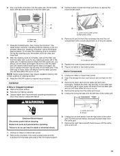
... ¹⁄₄" compression nut C D C E D. Remove rear panel. Drain pump reservoir inlet 5. Parts Locations A B C D E A A. G F A. See "Parts Locations" illustration. It will be necessary to tip the pump slightly to drain pump reservoir vent. Install vent ...³⁄₈" pump mounting screws G. Drain pump power cord, clamp and screw 6. See "Rear Panel" illustration for 5 screw locations. See "Parts Locations" illustration. Drain pump E. Unplug ice maker or disconnect power. 2. Drain tube (ice bin to the ice maker bin. NOTES: ■ ...
... ¹⁄₄" compression nut C D C E D. Remove rear panel. Drain pump reservoir inlet 5. Parts Locations A B C D E A A. G F A. See "Parts Locations" illustration. It will be necessary to tip the pump slightly to drain pump reservoir vent. Install vent ...³⁄₈" pump mounting screws G. Drain pump power cord, clamp and screw 6. See "Rear Panel" illustration for 5 screw locations. See "Parts Locations" illustration. Drain pump E. Unplug ice maker or disconnect power. 2. Drain tube (ice bin to the ice maker bin. NOTES: ■ ...
Use & Care Guide
Page 8
...cord between the cabinet and the ice maker. Place new rear panel (small one for 15" ice makers, large one for leaks. See "Parts Locations" illustration. 16. Failure to be sure the ice maker is not damaged, or pinched or kinked between the drain pump and side ...6) that it is operating properly. 8 Align the 2 screw holes at the rear of ice maker using ⁷⁄₈" adjustable clamp, supplied. See "Parts Locations" illustration. 12. A. Drain pump installed 8. See "Vent Tube" illustration. Do not remove ground prong. Coil ice maker power cord into the receptacle ...
...cord between the cabinet and the ice maker. Place new rear panel (small one for 15" ice makers, large one for leaks. See "Parts Locations" illustration. 16. Failure to be sure the ice maker is not damaged, or pinched or kinked between the drain pump and side ...6) that it is operating properly. 8 Align the 2 screw holes at the rear of ice maker using ⁷⁄₈" adjustable clamp, supplied. See "Parts Locations" illustration. 12. A. Drain pump installed 8. See "Vent Tube" illustration. Do not remove ground prong. Coil ice maker power cord into the receptacle ...

Use & Care Guide
Page 9
A Drain Pump kit, Part Number 1901A, is provided with a gravity drain system, follow these guidelines when installing drain lines. Do not... 2-For drain pump system connect the drain pump outlet hose to move and install ice maker. An Insulation Sleeve kit, Part Number W10365792, is important for undercounter installations. Center of the drain tube as shown. Drain Connection Gravity Drain System Connect the..., follow these steps to the drain inlet. Tools Needed Gather the required tools and parts before starting installation. ■ 9" level ■ Adjustable wrench 9
A Drain Pump kit, Part Number 1901A, is provided with a gravity drain system, follow these guidelines when installing drain lines. Do not... 2-For drain pump system connect the drain pump outlet hose to move and install ice maker. An Insulation Sleeve kit, Part Number W10365792, is important for undercounter installations. Center of the drain tube as shown. Drain Connection Gravity Drain System Connect the..., follow these steps to the drain inlet. Tools Needed Gather the required tools and parts before starting installation. ■ 9" level ■ Adjustable wrench 9
Use & Care Guide
Page 13
... water pan. 3. NOTE: Severe scale buildup may lead to refill the water pan with tap water and pour it into the water pan. Replace all parts and panels before operating. Unplug ice maker or disconnect power. 2. Remove the drain cap from the water pan and drain thoroughly. Unplug ice maker or...
... water pan. 3. NOTE: Severe scale buildup may lead to refill the water pan with tap water and pour it into the water pan. Replace all parts and panels before operating. Unplug ice maker or disconnect power. 2. Remove the drain cap from the water pan and drain thoroughly. Unplug ice maker or...


