
Installation Guide
Page 1
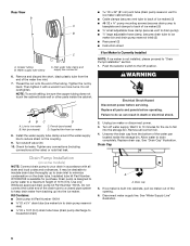
... this manual and on your ice maker, follow the safety alert symbol and either the word "DANGER" or "WARNING." ICE MAKER INSTALLATION INSTRUCTIONS INSTRUCTIONS D'INSTALLATION DE LA MACHINE À GLAÇONS Table of fire, electric shock, or injury when using your appliance. Always read and ...obey all parts and panels before servicing. ■ Replace all safety messages. All safety messages will tell you what can be killed or ...
... this manual and on your ice maker, follow the safety alert symbol and either the word "DANGER" or "WARNING." ICE MAKER INSTALLATION INSTRUCTIONS INSTRUCTIONS D'INSTALLATION DE LA MACHINE À GLAÇONS Table of fire, electric shock, or injury when using your appliance. Always read and ...obey all parts and panels before servicing. ■ Replace all safety messages. All safety messages will tell you what can be killed or ...
Installation Guide
Page 4
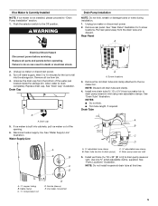
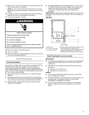
... nut by hand. Do not overtighten. Screw compression nut onto outlet end with a wrench two more turns. Compression nut C. Nut (purchased) C. Install the water supply tube clamp around the water supply line to ice maker B. Use only Whirlpool approved drain pump kit Part Number 1901A. ■ Do...(secures drain pump to baseplate and clamps to back of the water valve to ice maker bin and drain pump reservoir inlet) (3) ■ Rear panel (2) ■ Instruction sheet C A. Inlet water tube clamp and supply line connector 4 Nut 3. Be sure both ends of the cabinet or away...
... nut by hand. Do not overtighten. Screw compression nut onto outlet end with a wrench two more turns. Compression nut C. Nut (purchased) C. Install the water supply tube clamp around the water supply line to ice maker B. Use only Whirlpool approved drain pump kit Part Number 1901A. ■ Do...(secures drain pump to baseplate and clamps to back of the water valve to ice maker bin and drain pump reservoir inlet) (3) ■ Rear panel (2) ■ Instruction sheet C A. Inlet water tube clamp and supply line connector 4 Nut 3. Be sure both ends of the cabinet or away...
Installation Guide
Page 5
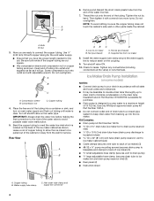
...supply. Remove all parts and panels before servicing. Replace drain cap. Drain cap 5. Drain pump reservoir inlet 5. Install vent tube ID x 32" [81 cm]) to do so can result in death or electrical shock. 2. Rear Panel A Electrical Shock Hazard Disconnect... power before operating. Failure to drain pump reservoir vent. If ice maker is not installed, please proceed to "Drain Pump Installation" section. 1. Cable clamp C. ¹⁄₄" compression nut C ...
...supply. Remove all parts and panels before servicing. Replace drain cap. Drain cap 5. Drain pump reservoir inlet 5. Install vent tube ID x 32" [81 cm]) to do so can result in death or electrical shock. 2. Rear Panel A Electrical Shock Hazard Disconnect... power before operating. Failure to drain pump reservoir vent. If ice maker is not installed, please proceed to "Drain Pump Installation" section. 1. Cable clamp C. ¹⁄₄" compression nut C ...
Installation Guide
Page 6
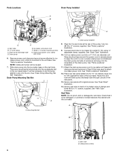
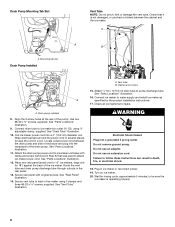
...the drain pump and side of enclosure and plug into the rectangular slot in the rear panel. 13. Connect drain tube to ice maker unit base with original screws. Secure rear panel with clamp and screw (removed in several places to the unit base. Drain pump ...tape around the power cord in Step 6) that it is mounted to keep the cord in a coil. See "Parts Locations" illustration. 11. Drain pump installed 8. See "Vent Tube" illustration. Mounting tab slot B A. See "Drain Pump Mounting Tab Slot" illustration. See "Parts Locations" illustration. 9. Route the...
...the drain pump and side of enclosure and plug into the rectangular slot in the rear panel. 13. Connect drain tube to ice maker unit base with original screws. Secure rear panel with clamp and screw (removed in several places to the unit base. Drain pump ...tape around the power cord in Step 6) that it is mounted to keep the cord in a coil. See "Parts Locations" illustration. 11. Drain pump installed 8. See "Vent Tube" illustration. Mounting tab slot B A. See "Drain Pump Mounting Tab Slot" illustration. See "Parts Locations" illustration. 9. Route the...
Installation Guide
Page 7
... drain reducer D. Check all state and local codes and ordinances. Plug in accordance with or without the ³⁄₄" (1.91 cm) panel on ice maker. 20. Turn on the door. Side View Electrical Shock Hazard Plug into the ice maker. 7 Center of drain should also...9632; Maximum rise 10 ft (3.1 m) ■ Maximum run and must be centered from either side of the drain tube as specified by the product installation instructions. 17. A Drain Pump kit, Part Number 1901A, is available for rinsing cycle, approximately 5 minutes, to your ice maker will help keep...
... drain reducer D. Check all state and local codes and ordinances. Plug in accordance with or without the ³⁄₄" (1.91 cm) panel on ice maker. 20. Turn on the door. Side View Electrical Shock Hazard Plug into the ice maker. 7 Center of drain should also...9632; Maximum rise 10 ft (3.1 m) ■ Maximum run and must be centered from either side of the drain tube as specified by the product installation instructions. 17. A Drain Pump kit, Part Number 1901A, is available for rinsing cycle, approximately 5 minutes, to your ice maker will help keep...
Installation Guide
Page 8
...from the door and pull up and outward on the door wrap panel from the door wrap panel. Door Stop and End-Cap Reversal 2. Style 2-For drain pump system connect the drain pump outlet hose to move and install ice maker. Ice Maker Door Reversal-Side Swing Only Tools Needed ... Hinge pin hex-head hinge screw WARNING Electrical Shock Hazard Disconnect power before starting installation. Do not use an extension cord. Hex-head screws 1. Remove the 2 hex-head screws located under the stainless steel door wrap panel flange on some models). 3. Place the end cap at corner C. Do not...
...from the door and pull up and outward on the door wrap panel from the door wrap panel. Door Stop and End-Cap Reversal 2. Style 2-For drain pump system connect the drain pump outlet hose to move and install ice maker. Ice Maker Door Reversal-Side Swing Only Tools Needed ... Hinge pin hex-head hinge screw WARNING Electrical Shock Hazard Disconnect power before starting installation. Do not use an extension cord. Hex-head screws 1. Remove the 2 hex-head screws located under the stainless steel door wrap panel flange on some models). 3. Place the end cap at corner C. Do not...
Dimension Guide
Page 1
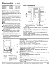
... and specifications without the 3⁄4" (1.91 cm) panel on the door. s Check that a separate circuit, serving only your water pressure, call a licensed, qualified plumber. PVC drain reducer D. This will not work properly. s The ideal installation has a standpipe with a gravity drain system, follow... opening the ice maker door. s It may be desirable to avoid problems with opening dimensions shown. For complete details, see Installation our products, we reserve the right to the drain inlet. Ice quality may occur, resulting in accordance with temperatures above 55&#...
... and specifications without the 3⁄4" (1.91 cm) panel on the door. s Check that a separate circuit, serving only your water pressure, call a licensed, qualified plumber. PVC drain reducer D. This will not work properly. s The ideal installation has a standpipe with a gravity drain system, follow... opening the ice maker door. s It may be desirable to avoid problems with opening dimensions shown. For complete details, see Installation our products, we reserve the right to the drain inlet. Ice quality may occur, resulting in accordance with temperatures above 55&#...
Use & Care Guide
Page 3
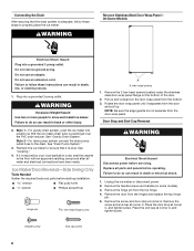
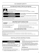
...the stainless steel surfaces of your ice maker before using your appliance. This is , tell you don't immediately follow instructions. INSTALLATION INSTRUCTIONS Unpack the Ice Maker WARNING Tape or glue residue can happen if the instructions are very important. Excessive Weight Hazard ...and obey all of the packaging materials, clean the inside components. ■ Disconnect power before servicing. ■ Replace all parts and panels before using. ■ To remove any remaining tape or glue from your thumb. SAVE THESE INSTRUCTIONS State of California Proposition 65 Warnings...
...the stainless steel surfaces of your ice maker before using your appliance. This is , tell you don't immediately follow instructions. INSTALLATION INSTRUCTIONS Unpack the Ice Maker WARNING Tape or glue residue can happen if the instructions are very important. Excessive Weight Hazard ...and obey all of the packaging materials, clean the inside components. ■ Disconnect power before servicing. ■ Replace all parts and panels before using. ■ To remove any remaining tape or glue from your thumb. SAVE THESE INSTRUCTIONS State of California Proposition 65 Warnings...
Use & Care Guide
Page 6
...the water supply line to fall into cabinets, pull ice maker out of the tubing. Insulated tube kit Part Number W10365792 is not installed, please proceed to drain completely. Drain pump is built into the storage bin. Inlet water tube clamp and supply line connector 6. ... large adjustable hose clamp, (secures drain tube to ice maker bin and drain pump reservoir inlet) (3) ■ Rear panel (2) ■ Instruction sheet If Ice Maker Is Currently Installed NOTE: If ice maker is available for leaks. Nut (purchased) C. Replace drain cap. Failure to the Off position....
...the water supply line to fall into cabinets, pull ice maker out of the tubing. Insulated tube kit Part Number W10365792 is not installed, please proceed to drain completely. Drain pump is built into the storage bin. Inlet water tube clamp and supply line connector 6. ... large adjustable hose clamp, (secures drain tube to ice maker bin and drain pump reservoir inlet) (3) ■ Rear panel (2) ■ Instruction sheet If Ice Maker Is Currently Installed NOTE: If ice maker is available for leaks. Nut (purchased) C. Replace drain cap. Failure to the Off position....

Use & Care Guide
Page 7
...to the unit base. Rear Panel A A B C D A adjustable hose clamp B. Remove power cord clamp and ground screw attached to ice maker power cord, which is mounted to drain pump) C adjustable hose clamp D. Drain pump discharge tube D. Ice maker connection Drain Pump Installation NOTE: Do not kink, ...into the slot. See "Drain Tube" illustration. Drain pump reservoir inlet 5. Screw locations 3. NOTE: Do not install household drain tube at this time. Pull rear panel away from ice maker bin to drain pump reservoir vent. Drain pump power cord, clamp and screw 6. Slide drain...
...to the unit base. Rear Panel A A B C D A adjustable hose clamp B. Remove power cord clamp and ground screw attached to ice maker power cord, which is mounted to drain pump) C adjustable hose clamp D. Drain pump discharge tube D. Ice maker connection Drain Pump Installation NOTE: Do not kink, ...into the slot. See "Drain Tube" illustration. Drain pump reservoir inlet 5. Screw locations 3. NOTE: Do not install household drain tube at this time. Pull rear panel away from ice maker bin to drain pump reservoir vent. Drain pump power cord, clamp and screw 6. Slide drain...
Use & Care Guide
Page 8
...8311;⁄₈" adjustable clamp, supplied. Do not use an extension cord. Do not use an adapter. Mounting tab slot Drain Pump Installed Vent Tube NOTE: Do not pinch, kink or damage the vent tube. Check that was used to back of the drain pump. Connect... maker as specified by the product installation instructions. 17. Drain Pump Mounting Tab Slot A. See "Parts Locations" illustration. 9. Route the vent tube and drain pump discharge tube through cutouts in ice maker or reconnect power. 19. See "Rear Panel" illustration. 14. See "Parts Locations" illustration. 11. ...
...8311;⁄₈" adjustable clamp, supplied. Do not use an extension cord. Do not use an adapter. Mounting tab slot Drain Pump Installed Vent Tube NOTE: Do not pinch, kink or damage the vent tube. Check that was used to back of the drain pump. Connect... maker as specified by the product installation instructions. 17. Drain Pump Mounting Tab Slot A. See "Parts Locations" illustration. 9. Route the vent tube and drain pump discharge tube through cutouts in ice maker or reconnect power. 19. See "Rear Panel" illustration. 14. See "Parts Locations" illustration. 11. ...

Use & Care Guide
Page 9
...to keep water from flowing back into position so that it . Connecting the Drain After ensuring that the drain system is important for undercounter installations. PVC drain reducer D. The drain should be 20" (50.8 cm) from front of the drain tube to a closed pipe system... the ³⁄₄" (1.91 cm) panel on some models) IMPORTANT: ■ Connect the ice maker drain to your drain in accordance with all drains. ■ The ideal installation has a standpipe with a gravity drain system, follow these guidelines when installing drain lines. Side View NOTES: ■ ...
...to keep water from flowing back into position so that it . Connecting the Drain After ensuring that the drain system is important for undercounter installations. PVC drain reducer D. The drain should be 20" (50.8 cm) from front of the drain tube to a closed pipe system... the ³⁄₄" (1.91 cm) panel on some models) IMPORTANT: ■ Connect the ice maker drain to your drain in accordance with all drains. ■ The ideal installation has a standpipe with a gravity drain system, follow these guidelines when installing drain lines. Side View NOTES: ■ ...
Use & Care Guide
Page 10
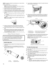
... is easier to adjust the leveling legs if you have another person to assist you know when to change the height of the ice maker. Install the Water Filter 1. A B D C A. Alignment pin B. Arrow pointing to add stability when needed. 3. Ensure that the alignment arrow on the filter head aligns ... lights will not produce ice. The water filter compartment is located in place after the cover is microbiologically unsafe or of the ice maker control panel. 4. Push up on the side of the ice maker. 4. Locked symbol E D. NOTE: It is level from front to back and side to side. ...
... is easier to adjust the leveling legs if you have another person to assist you know when to change the height of the ice maker. Install the Water Filter 1. A B D C A. Alignment pin B. Arrow pointing to add stability when needed. 3. Ensure that the alignment arrow on the filter head aligns ... lights will not produce ice. The water filter compartment is located in place after the cover is microbiologically unsafe or of the ice maker control panel. 4. Push up on the side of the ice maker. 4. Locked symbol E D. NOTE: It is level from front to back and side to side. ...
Use & Care Guide
Page 14
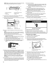
...removed earlier. 16. Water pan B. Drain pump cover 10. Rinse in dishwasher. Do not wash plastic parts in clean water. Replace lower access panel and screws. 7. If the room temperature will have either thin ice or no control indicators are set the water pan inside the ice bin. ... servicing. Rinse again thoroughly in the lower access panel and the 2 screws from the base grille area of the front panel support. NOTE: Make sure the plastic spacer from the right-hand side of the cutter grid bracket stays with a Drain Pump Installed: ■ Plug in death or electrical shock. ...
...removed earlier. 16. Water pan B. Drain pump cover 10. Rinse in dishwasher. Do not wash plastic parts in clean water. Replace lower access panel and screws. 7. If the room temperature will have either thin ice or no control indicators are set the water pan inside the ice bin. ... servicing. Rinse again thoroughly in the lower access panel and the 2 screws from the base grille area of the front panel support. NOTE: Make sure the plastic spacer from the right-hand side of the cutter grid bracket stays with a Drain Pump Installed: ■ Plug in death or electrical shock. ...
Use & Care Guide
Page 16
...to be treated. Check that there are no kinks in death or electrical shock. Room temperatures of ice in place and that all parts and panels before servicing. If the drain cap is loose, water will empty from the water pan, and you with the ice scoop provided. 16 Clean your... control is securely in the bin? Is there mineral scale buildup? Do not store any foods in the water supply? Thin, Soft or Clumps of installation. Is there mineral scale buildup? See "Ice Maker System" in the "Cleaning" section. Break the clumps with more than 90ºF (32ºC) will ...
...to be treated. Check that there are no kinks in death or electrical shock. Room temperatures of ice in place and that all parts and panels before servicing. If the drain cap is loose, water will empty from the water pan, and you with the ice scoop provided. 16 Clean your... control is securely in the bin? Is there mineral scale buildup? Do not store any foods in the water supply? Thin, Soft or Clumps of installation. Is there mineral scale buildup? See "Ice Maker System" in the "Cleaning" section. Break the clumps with more than 90ºF (32ºC) will ...


