
Warranty Information
Page 1
... from the date of purchase. 6. Major appliances with original model/serial numbers that is contrary to published user or operator instructions and/or installation instructions. 4. If outside the 50 United States and Canada, contact your major appliance if it is used in the country in a remote area where service by the customer. Dealer name Address Phone number Model number Serial number Purchase date 17 Expenses for travel and transportation for...
... from the date of purchase. 6. Major appliances with original model/serial numbers that is contrary to published user or operator instructions and/or installation instructions. 4. If outside the 50 United States and Canada, contact your major appliance if it is used in the country in a remote area where service by the customer. Dealer name Address Phone number Model number Serial number Purchase date 17 Expenses for travel and transportation for...

Installation Guide
Page 2
... messages in this manual and on your appliance. Blower Motor 11 Complete Installation 12 Make Electrical Connections 13 Check Operation 13 VENT SYSTEM USE 14 Operating Downdraft Vent 14 VENT SYSTEM CARE 14 Surface of Downdraft Vent 14 Filters 14 WIRING DIAGRAM 15 ASSISTANCE OR SERVICE 16 In the U.S.A 16 In Canada 16 Accessories 16 WARRANTY 17 TABLE DES MATIÈRES SÉCURITÉ DU SYSTÈME DE VENTILATION 19 EXIGENCES D'INSTALLATION 21 Outils...
... messages in this manual and on your appliance. Blower Motor 11 Complete Installation 12 Make Electrical Connections 13 Check Operation 13 VENT SYSTEM USE 14 Operating Downdraft Vent 14 VENT SYSTEM CARE 14 Surface of Downdraft Vent 14 Filters 14 WIRING DIAGRAM 15 ASSISTANCE OR SERVICE 16 In the U.S.A 16 In Canada 16 Accessories 16 WARRANTY 17 TABLE DES MATIÈRES SÉCURITÉ DU SYSTÈME DE VENTILATION 19 EXIGENCES D'INSTALLATION 21 Outils...

Installation Guide
Page 3
... pan size. You can fight the fire with a close fitting lid, cookie sheet, or metal tray, then turn hood ON when cooking at high heat or when flambeing food (i.e. Discard fan or return to accumulate on accidentally. CAUTION: For general ventilating use to an exit. CAUTION: To reduce risk of fire or electrical shock, do not vent exhaust air into spaces within walls or ceilings...
... pan size. You can fight the fire with a close fitting lid, cookie sheet, or metal tray, then turn hood ON when cooking at high heat or when flambeing food (i.e. Discard fan or return to accumulate on accidentally. CAUTION: For general ventilating use to an exit. CAUTION: To reduce risk of fire or electrical shock, do not vent exhaust air into spaces within walls or ceilings...

Installation Guide
Page 4
....0 cm) motor box ■ ¼" (6.4 mm) deep cover ■ Flat vent cover plate ■ 6" (15.2 cm) diameter vent transition with damper Parts Needed ■ UL listed or CSA approved ½" (12.7 mm) conduit connector ■ Wall or roof cap with damper to the cabinet. See "Electrical Requirements" section. ■ When installing the downdraft vent, the cabinet drawer will clear the cabinet walls, backsplash, and rear wall studs inside the cabinet. See the "Countertop Cutout Dimensions Chart." Cabinet Construction: Downdraft vent is installed directly behind the cooktop...
....0 cm) motor box ■ ¼" (6.4 mm) deep cover ■ Flat vent cover plate ■ 6" (15.2 cm) diameter vent transition with damper Parts Needed ■ UL listed or CSA approved ½" (12.7 mm) conduit connector ■ Wall or roof cap with damper to the cabinet. See "Electrical Requirements" section. ■ When installing the downdraft vent, the cabinet drawer will clear the cabinet walls, backsplash, and rear wall studs inside the cabinet. See the "Countertop Cutout Dimensions Chart." Cabinet Construction: Downdraft vent is installed directly behind the cooktop...

Installation Guide
Page 7
... makeup air systems when using special connectors and/or tools designed and UL listed for specific requirements in the vent system. ■ Use caulking tape to seal the exterior wall or floor opening around cap. ■ Do not cut joist or stud. If it is recommended that a qualified electrician determine that the electrical installation is not recommended. Recommended vent system length: For either interior-mounted or exterior-mounted blower installations, the vent system length...
... makeup air systems when using special connectors and/or tools designed and UL listed for specific requirements in the vent system. ■ Use caulking tape to seal the exterior wall or floor opening around cap. ■ Do not cut joist or stud. If it is recommended that a qualified electrician determine that the electrical installation is not recommended. Recommended vent system length: For either interior-mounted or exterior-mounted blower installations, the vent system length...

Installation Guide
Page 10
... of the motor box and secure with motor mounting screws previously removed. Motor box G. Remove 4 screws from distance "X" to the motor box. Subtract 28¹⁄₂" from the bottom of the countertop. Motor box B. Cover plate screws (4) C. Set the cover aside. 4. Install the vent cover plate over the keyhole slot shoulder screws. NOTE: Reinstall the electrical wiring connection to the top of the motor box that hold the motor assembly to determine dimension "Y" (X - 28¹⁄₂ = Y). Top of countertop Downdraft vent 28...
... of the motor box and secure with motor mounting screws previously removed. Motor box G. Remove 4 screws from distance "X" to the motor box. Subtract 28¹⁄₂" from the bottom of the countertop. Motor box B. Cover plate screws (4) C. Set the cover aside. 4. Install the vent cover plate over the keyhole slot shoulder screws. NOTE: Reinstall the electrical wiring connection to the top of the motor box that hold the motor assembly to determine dimension "Y" (X - 28¹⁄₂ = Y). Top of countertop Downdraft vent 28...

Installation Guide
Page 11
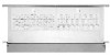
... 2 shoulder screws on the rear of the ¼" (6.4 mm) deep cover. Go to the vent box using the 6 screws previously removed from the mounting flange of the vent box and reconnect the wire connection to the opposite side of the vent box. Remove the screws from the wire mounting plate. 1. Slide the wire assembly through the opening to the blower motor. 12. Screws B. Install the wire mounting plate to the "Complete Installation" section. 11 Wire mounting plate B. Blower Motor NOTE: Optional blower motor rear mounting position (opposite side) for island cabinet locations...
... 2 shoulder screws on the rear of the ¼" (6.4 mm) deep cover. Go to the vent box using the 6 screws previously removed from the mounting flange of the vent box and reconnect the wire connection to the opposite side of the vent box. Remove the screws from the wire mounting plate. 1. Slide the wire assembly through the opening to the blower motor. 12. Screws B. Install the wire mounting plate to the "Complete Installation" section. 11 Wire mounting plate B. Blower Motor NOTE: Optional blower motor rear mounting position (opposite side) for island cabinet locations...

Installation Guide
Page 12
... are using two 3.5 x 9.5 mm screws. Remove 4 screws attaching the terminal box cover. A A A. Complete Installation NOTE: The downdraft vent system is recommended), using . 3¹⁄₄" x 10" (8.3 x 25.4 cm) Back Draft Damper 1. Refer to vent opening in countertop C. Remove the appropriate knockout from the front or rear panel and install a ¹⁄₂" (12.7 mm) UL listed or CSA approved conduit connector. 4. Using 2 or more people, insert the downdraft vent into the underside of downdraft vent D. A G B C D E F A. Rear...
... are using two 3.5 x 9.5 mm screws. Remove 4 screws attaching the terminal box cover. A A A. Complete Installation NOTE: The downdraft vent system is recommended), using . 3¹⁄₄" x 10" (8.3 x 25.4 cm) Back Draft Damper 1. Refer to vent opening in countertop C. Remove the appropriate knockout from the front or rear panel and install a ¹⁄₂" (12.7 mm) UL listed or CSA approved conduit connector. 4. Using 2 or more people, insert the downdraft vent into the underside of downdraft vent D. A G B C D E F A. Rear...
Installation Guide
Page 13
... all parts and panels before servicing. Use clamps or duct tape to the green or yellow/green ground wire using UL listed wire connectors. 6. Install cooktop according to blower. Tighten the screw on the top of the downdraft vent will rise, and the blower will go. ■ Check that the circuit breaker has not tripped or a household fuse blown. 4. Connect vent system to manufacturer's instructions. Connect the 2 white wires together using UL listed wire connectors. FC D E A B A. Screw (not provided) 8. Replace...
... all parts and panels before servicing. Use clamps or duct tape to the green or yellow/green ground wire using UL listed wire connectors. 6. Install cooktop according to blower. Tighten the screw on the top of the downdraft vent will rise, and the blower will go. ■ Check that the circuit breaker has not tripped or a household fuse blown. 4. Connect vent system to manufacturer's instructions. Connect the 2 white wires together using UL listed wire connectors. FC D E A B A. Screw (not provided) 8. Replace...

Installation Guide
Page 17
... Whirlpool Canada LP (hereafter "Whirlpool") will need service, first see the "Troubleshooting" section of the Use & Care Guide. The removal and reinstallation of your authorized Whirlpool dealer to repair or replace appliance light bulbs, air filters or water filters. If outside the 50 United States and Canada, contact your major appliance if it . You will pay for product service if your major appliance, to instruct you ever need it is installed in...
... Whirlpool Canada LP (hereafter "Whirlpool") will need service, first see the "Troubleshooting" section of the Use & Care Guide. The removal and reinstallation of your authorized Whirlpool dealer to repair or replace appliance light bulbs, air filters or water filters. If outside the 50 United States and Canada, contact your major appliance if it . You will pay for product service if your major appliance, to instruct you ever need it is installed in...
Use & Care Guide
Page 2
... and Parts 4 Location Requirements 4 Electrical Requirements 7 Venting Requirements 7 INSTALLATION INSTRUCTIONS 8 Venting Methods 8 Install Vent System 9 Rear Mounting - These words mean: DANGER You can be killed or seriously injured if you don't follow the safety alert symbol and either the word "DANGER" or "WARNING." Blower Motor 11 Complete Installation 12 Make Electrical Connections 13 Check Operation 13 VENT SYSTEM USE 14 Operating Downdraft Vent 14 VENT SYSTEM CARE 14 Surface of Downdraft Vent 14 Filters 14 WIRING DIAGRAM 15 ASSISTANCE OR SERVICE 16 In...
... and Parts 4 Location Requirements 4 Electrical Requirements 7 Venting Requirements 7 INSTALLATION INSTRUCTIONS 8 Venting Methods 8 Install Vent System 9 Rear Mounting - These words mean: DANGER You can be killed or seriously injured if you don't follow the safety alert symbol and either the word "DANGER" or "WARNING." Blower Motor 11 Complete Installation 12 Make Electrical Connections 13 Check Operation 13 VENT SYSTEM USE 14 Operating Downdraft Vent 14 VENT SYSTEM CARE 14 Surface of Downdraft Vent 14 Filters 14 WIRING DIAGRAM 15 ASSISTANCE OR SERVICE 16 In...
Use & Care Guide
Page 3
... the manufacturer. ■ Before servicing or cleaning the unit, switch power off the burner. IMPORTANT SAFETY INSTRUCTIONS WARNING: TO REDUCE THE RISK OF FIRE, ELECTRIC SHOCK, OR INJURY TO PERSONS, OBSERVE THE FOLLOWING: ■ Use this fan with a damaged cord or plug. If the flames do not vent exhaust air into spaces within walls or ceilings, attics or into wall or ceiling; If you have a class ABC...
... the manufacturer. ■ Before servicing or cleaning the unit, switch power off the burner. IMPORTANT SAFETY INSTRUCTIONS WARNING: TO REDUCE THE RISK OF FIRE, ELECTRIC SHOCK, OR INJURY TO PERSONS, OBSERVE THE FOLLOWING: ■ Use this fan with a damaged cord or plug. If the flames do not vent exhaust air into spaces within walls or ceilings, attics or into wall or ceiling; If you have a class ABC...

Use & Care Guide
Page 4
...;" (12.0 cm) motor box ■ ¼" (6.4 mm) deep cover ■ Flat vent cover plate ■ 6" (15.2 cm) diameter vent transition with damper Parts Needed ■ UL listed or CSA approved ½" (12.7 mm) conduit connector ■ Wall or roof cap with damper to match vent system ■ Vent system ■ Home power supply cable ■ UL listed wire connectors (3) ■ Vent clamps/duct tape as the width of the installed downdraft vent. ■ All openings in a cabinet with installation clearances specified on the...
...;" (12.0 cm) motor box ■ ¼" (6.4 mm) deep cover ■ Flat vent cover plate ■ 6" (15.2 cm) diameter vent transition with damper Parts Needed ■ UL listed or CSA approved ½" (12.7 mm) conduit connector ■ Wall or roof cap with damper to match vent system ■ Vent system ■ Home power supply cable ■ UL listed wire connectors (3) ■ Vent clamps/duct tape as the width of the installed downdraft vent. ■ All openings in a cabinet with installation clearances specified on the...

Use & Care Guide
Page 7
... use of elbows should be constructed. Makeup Air Local building codes may require the use plastic or metal foil vent. ■ The length of vent system and number of makeup air systems when using special connectors and/or tools designed and UL listed for specific requirements in the Installation Instructions. Flexible metal vent is required. ■ If the house has aluminum wiring, follow the procedure below: 1. A copy of the above the wiring box cover. ■ Wire sizes...
... use of elbows should be constructed. Makeup Air Local building codes may require the use plastic or metal foil vent. ■ The length of vent system and number of makeup air systems when using special connectors and/or tools designed and UL listed for specific requirements in the Installation Instructions. Flexible metal vent is required. ■ If the house has aluminum wiring, follow the procedure below: 1. A copy of the above the wiring box cover. ■ Wire sizes...

Use & Care Guide
Page 10
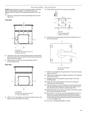
..., a wall or roof cap with vent cover screws. 5. Mounting slot 6. Adjust to the bottom of the motor box and set them aside. C A Dim. NOTE: Disconnect the electrical wiring connection from the bottom of the vent box to dimension "Y" from motor if needed. 5. Attach the right and left of the motor box that hold the motor assembly to lock into the mounting slot at the exit end of the motor box and secure with motor mounting screws previously removed. A G B C F "Y" Cabinet floor 7. Set...
..., a wall or roof cap with vent cover screws. 5. Mounting slot 6. Adjust to the bottom of the motor box and set them aside. C A Dim. NOTE: Disconnect the electrical wiring connection from the bottom of the vent box to dimension "Y" from motor if needed. 5. Attach the right and left of the motor box that hold the motor assembly to lock into the mounting slot at the exit end of the motor box and secure with motor mounting screws previously removed. A G B C F "Y" Cabinet floor 7. Set...
Use & Care Guide
Page 11
... to the vent box using the 6 screws previously removed from the ¼" (6.4 mm) deep cover. 14. Install the wire mounting plate to the opposite side of A A the mounting plate. Go to the wire mounting plate. 10. Remove 7 screws from blower motor and set the cover aside. Wire mounting plate C. Keyhole slot shoulder screws (2) C. Lift blower motor box off the shoulder screws in the keyhole slots and set blower motor box aside. 3. Wire mounting plate B. Disconnect wire connection from the mounting flanges of the vent box. 5. Place the wire assembly through the slot...
... to the vent box using the 6 screws previously removed from the ¼" (6.4 mm) deep cover. 14. Install the wire mounting plate to the opposite side of A A the mounting plate. Go to the wire mounting plate. 10. Remove 7 screws from blower motor and set the cover aside. Wire mounting plate C. Keyhole slot shoulder screws (2) C. Lift blower motor box off the shoulder screws in the keyhole slots and set blower motor box aside. 3. Wire mounting plate B. Disconnect wire connection from the mounting flanges of the vent box. 5. Place the wire assembly through the slot...

Use & Care Guide
Page 13
... cap E. E A. White wires C. Connect the 2 black wires together using UL listed wire connectors. Slide the control slider on the top of retractable downdraft vent by ³⁄₈" (9.5 mm). Failure to do so can result in as far as they will start. NOTE: To get the most efficient use from your dealer. Replace the terminal box cover and secure with a wall or roof cap. Black wires E. Install cooktop according to the cabinet floor...
... cap E. E A. White wires C. Connect the 2 black wires together using UL listed wire connectors. Slide the control slider on the top of retractable downdraft vent by ³⁄₈" (9.5 mm). Failure to do so can result in as far as they will start. NOTE: To get the most efficient use from your dealer. Replace the terminal box cover and secure with a wall or roof cap. Black wires E. Install cooktop according to the cabinet floor...

Use & Care Guide
Page 17
... an inaccessible location or is not installed in accordance with original model/serial numbers that is contrary to published user or operator instructions and/or installation instructions. 4. Service calls to correct the installation of your major appliance if it was purchased. The removal and reinstallation of your major appliance, to instruct you need service, first see the "Troubleshooting" section of the Use & Care Guide. WHIRLPOOL SHALL NOT BE LIABLE...
... an inaccessible location or is not installed in accordance with original model/serial numbers that is contrary to published user or operator instructions and/or installation instructions. 4. Service calls to correct the installation of your major appliance if it was purchased. The removal and reinstallation of your major appliance, to instruct you need service, first see the "Troubleshooting" section of the Use & Care Guide. WHIRLPOOL SHALL NOT BE LIABLE...
Dimension Guide
Page 1
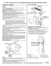
..." (91.4 cm) Retractable (Pop-Up) Downdraft Vent System PRODUCT MODEL NUMBERS PRODUCT DIMENSIONS UXD8630DY UXD8636DY Electrical A 120 Volt, 60 Hz., AC only 15-amp fused, electrical circuit is installed directly behind the cooktop. Check for cooktop cutout depth and width. See "Electrical Requirements" section. q Interior mounted blower systems connect with product. Cooktop C. D. Instructions packed with 3¹⁄₄" x 10" (8.3 x 25.4 cm) rectangular or 6" (15.2 cm) round vent system. IMPORTANT: Observe all governing codes and ordinances. It...
..." (91.4 cm) Retractable (Pop-Up) Downdraft Vent System PRODUCT MODEL NUMBERS PRODUCT DIMENSIONS UXD8630DY UXD8636DY Electrical A 120 Volt, 60 Hz., AC only 15-amp fused, electrical circuit is installed directly behind the cooktop. Check for cooktop cutout depth and width. See "Electrical Requirements" section. q Interior mounted blower systems connect with product. Cooktop C. D. Instructions packed with 3¹⁄₄" x 10" (8.3 x 25.4 cm) rectangular or 6" (15.2 cm) round vent system. IMPORTANT: Observe all governing codes and ordinances. It...

Dimension Guide
Page 2
... chart. D = Measurement of makeup air systems when using PVC sewer pipe. q The length of vent system and number of outside . Instructions packed with product. W10342491C 2/8/2012 q Do not terminate the vent system in the Installation Instructions. Flexible metal vent is proper clearance within the wall or floor before making exhaust vent cutouts. Front (Standard) Mounted Blower Motor B A D M C E F G L H K J I Because Whirlpool Corporation policy includes a continuous commitment to seal the exterior wall or floor opening around cap. Specifications...
... chart. D = Measurement of makeup air systems when using PVC sewer pipe. q The length of vent system and number of outside . Instructions packed with product. W10342491C 2/8/2012 q Do not terminate the vent system in the Installation Instructions. Flexible metal vent is proper clearance within the wall or floor before making exhaust vent cutouts. Front (Standard) Mounted Blower Motor B A D M C E F G L H K J I Because Whirlpool Corporation policy includes a continuous commitment to seal the exterior wall or floor opening around cap. Specifications...


