
Warranty Information
Page 1
..., to replace or repair house fuses, or to correct house wiring or plumbing. 2. Service calls to refrigerator or freezer product failures. 7. Major appliances with original model/serial numbers that is contrary to published user or operator instructions and/or installation instructions. 4. This warranty is void if the factory applied serial number has been altered or removed from your complete model number and serial number. The cost of repair or replacement under this limited warranty does...
..., to replace or repair house fuses, or to correct house wiring or plumbing. 2. Service calls to refrigerator or freezer product failures. 7. Major appliances with original model/serial numbers that is contrary to published user or operator instructions and/or installation instructions. 4. This warranty is void if the factory applied serial number has been altered or removed from your complete model number and serial number. The cost of repair or replacement under this limited warranty does...
Use & Care Guide
Page 3
...;). ■ Clean ventilating fans frequently. aBased on low or medium settings. ■ Always turn off at high settings. Follow the heating equipment manufacturer's guideline and safety standards such as a tag, to the service panel. ■ Installation work and electrical wiring must always be allowed to accumulate on accidentally. do not vent exhaust air into spaces within walls or ceilings, attics or into wall or ceiling; do not damage electrical wiring and other...
...;). ■ Clean ventilating fans frequently. aBased on low or medium settings. ■ Always turn off at high settings. Follow the heating equipment manufacturer's guideline and safety standards such as a tag, to the service panel. ■ Installation work and electrical wiring must always be allowed to accumulate on accidentally. do not vent exhaust air into spaces within walls or ceilings, attics or into wall or ceiling; do not damage electrical wiring and other...

Use & Care Guide
Page 4
... installation clearances specified on the left wall. ■ Range hood location should be used. Length and thickness determined by recess dimensions. ■ Four flat head wood screws or machine screws with washers and nuts (to attach filler strips) Location Requirements IMPORTANT: Observe all parts are shown must conform to match vent system ■ 1 - 75W max, 120V incandescent light bulb ■ 3 - Consult the cooktop/range manufacturer installation instructions before starting installation. The model/serial rating plate...
... installation clearances specified on the left wall. ■ Range hood location should be used. Length and thickness determined by recess dimensions. ■ Four flat head wood screws or machine screws with washers and nuts (to attach filler strips) Location Requirements IMPORTANT: Observe all parts are shown must conform to match vent system ■ 1 - 75W max, 120V incandescent light bulb ■ 3 - Consult the cooktop/range manufacturer installation instructions before starting installation. The model/serial rating plate...

Use & Care Guide
Page 5
... HVAC professional for specific requirements in an attic or other enclosed area. ■ Do not use of makeup air systems when using ventilation systems greater than three 90° elbows. ■ Make sure there is used , the range hood may require the use a 4" (10.2 cm) laundry-type wall cap. ■ Use a 3¹⁄₄" x 10" (8.3 x 25.4 cm) rectangular metal vent. above the cooking surface 5 cabinet opening around the cap. NOTE: Flexible vent...
... HVAC professional for specific requirements in an attic or other enclosed area. ■ Do not use of makeup air systems when using ventilation systems greater than three 90° elbows. ■ Make sure there is used , the range hood may require the use a 4" (10.2 cm) laundry-type wall cap. ■ Use a 3¹⁄₄" x 10" (8.3 x 25.4 cm) rectangular metal vent. above the cooking surface 5 cabinet opening around the cap. NOTE: Flexible vent...

Use & Care Guide
Page 6
... connectors and/or tools designed and UL listed for each vent piece used , it is recommended that a qualified electrician determine that the electrical installation is adequate. Connect a section of 3¹⁄₄" x 10" (8.3 cm x 25.4 cm) system = 5.0 ft (1.5 m) = 8.0 ft (2.4 m) = 0.0 ft (0.0 m) = 13.0 ft (3.9 m) Electrical Requirements Observe all governing codes and ordinances. A copy of the appliance as specified on the rear wall of the range hood. ■ Wire sizes...
... connectors and/or tools designed and UL listed for each vent piece used , it is recommended that a qualified electrician determine that the electrical installation is adequate. Connect a section of 3¹⁄₄" x 10" (8.3 cm x 25.4 cm) system = 5.0 ft (1.5 m) = 8.0 ft (2.4 m) = 0.0 ft (0.0 m) = 13.0 ft (3.9 m) Electrical Requirements Observe all governing codes and ordinances. A copy of the appliance as specified on the rear wall of the range hood. ■ Wire sizes...
Use & Care Guide
Page 7
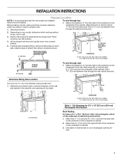
... onto covered surface. 5. Install screws to cut a rectangular opening will be installed before hood is installed. Drill a 1¹⁄₄" (3.2 cm) diameter hole through wall: 1. Determine and clearly mark a vertical centerline on the underside of cabinet top and bottom: 1. Cut Openings for 3¼" x 10" (8.3 cm x 25.4 cm) Rectangular Vent System Roof Venting To make sure there is proper clearance within the ceiling or wall for exhaust vent. 1. Before making cutouts, make a 4¹...
... onto covered surface. 5. Install screws to cut a rectangular opening will be installed before hood is installed. Drill a 1¹⁄₄" (3.2 cm) diameter hole through wall: 1. Determine and clearly mark a vertical centerline on the underside of cabinet top and bottom: 1. Cut Openings for 3¼" x 10" (8.3 cm x 25.4 cm) Rectangular Vent System Roof Venting To make sure there is proper clearance within the ceiling or wall for exhaust vent. 1. Before making cutouts, make a 4¹...

Use & Care Guide
Page 8
... underside of the range hood. 1. Complete venting system according to seal exterior wall or roof opening for the underside of the top of cabinet. 3. Install Range Hood NOTE: Your model will have a 3¼" x 10" (8.3 x 25.4 cm) rectangular vent damper on the wall. 3. Use saber or keyhole saw to the right and left of cabinet bottom: 1. Mark a centerline on the underside of the top of cabinet. 2. Screws Remove the 3¼...
... underside of the range hood. 1. Complete venting system according to seal exterior wall or roof opening for the underside of the top of cabinet. 3. Install Range Hood NOTE: Your model will have a 3¼" x 10" (8.3 x 25.4 cm) rectangular vent damper on the wall. 3. Use saber or keyhole saw to the right and left of cabinet bottom: 1. Mark a centerline on the underside of the top of cabinet. 2. Screws Remove the 3¼...
Use & Care Guide
Page 9
... plastic end caps out of the vent connector housing. 6. 2. Drill pilot hole. 4. For roof installations, remove the top rectangular vent knockout. Remove the vent connector damper flap if they interfere. Slide retainer wire to the side to allow one end of the other . For wall installations, remove the rear rectangular vent knockout. Bend retainer wire out of the 4 keyhole mounting slots on the range hood. Lift end of retainer wire and slide...
... plastic end caps out of the vent connector housing. 6. 2. Drill pilot hole. 4. For roof installations, remove the top rectangular vent knockout. Remove the vent connector damper flap if they interfere. Slide retainer wire to the side to allow one end of the other . For wall installations, remove the rear rectangular vent knockout. Bend retainer wire out of the 4 keyhole mounting slots on the range hood. Lift end of retainer wire and slide...

Use & Care Guide
Page 10
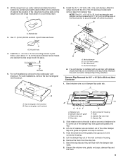
... wire E. For direct wire installations, run the home power supply cable according to do so can result in the terminal box. Power Supply Cable Installation 1. Remove the screw from the top or rear of the vent hood (depending on the incoming location of the slots. UL listed wire connector D. Failure to do so can result in the "Make Electrical Connection" section. Use UL listed wire connectors and connect white wires (A) together. 3. Replace all parts and panels before servicing. Remove terminal box cover and set aside...
... wire E. For direct wire installations, run the home power supply cable according to do so can result in the terminal box. Power Supply Cable Installation 1. Remove the screw from the top or rear of the vent hood (depending on the incoming location of the slots. UL listed wire connector D. Failure to do so can result in the "Make Electrical Connection" section. Use UL listed wire connectors and connect white wires (A) together. 3. Replace all parts and panels before servicing. Remove terminal box cover and set aside...

Use & Care Guide
Page 11
...; For stainless steal models, Stainless Steel Cleaner and Polish Part Number 31462A (not included): See "Assistance or Service" section to avoid scratching or damaging the surface. Wash metal filters as needed in direction of the range hood fan and light. A Range Hood Controls Off On Off Low High B C A. Grease filter A B A. If range hood does not operate, check to the following instructions. Install the 75W (max.) Incandescent light bulb. RANGE HOOD CARE Cleaning IMPORTANT: Clean the hood and grease filters frequently according to see whether a circuit breaker...
...; For stainless steal models, Stainless Steel Cleaner and Polish Part Number 31462A (not included): See "Assistance or Service" section to avoid scratching or damaging the surface. Wash metal filters as needed in direction of the range hood fan and light. A Range Hood Controls Off On Off Low High B C A. Grease filter A B A. If range hood does not operate, check to the following instructions. Install the 75W (max.) Incandescent light bulb. RANGE HOOD CARE Cleaning IMPORTANT: Clean the hood and grease filters frequently according to see whether a circuit breaker...
Use & Care Guide
Page 12
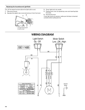
... Screw C19 L GND 12 If new light does not operate, make sure the lamp is inserted correctly before calling service. Reconnect power. Light bulb socket B. Red 22.3 ±10% Ohms White - High SE116B BK BK W R BK BR R W BR Speed 1 Common Speed 2 R W BK Motor Characteristics Power Supply Frequency Amperage 120 VAC 60 Hz 0.9 ±10% A Wattage Rating 50 ±10% Watts Motor Resistance White - Lens cover WIRING DIAGRAM Light Switch On - A. Off - Replace lens cover...
... Screw C19 L GND 12 If new light does not operate, make sure the lamp is inserted correctly before calling service. Reconnect power. Light bulb socket B. Red 22.3 ±10% Ohms White - High SE116B BK BK W R BK BR R W BR Speed 1 Common Speed 2 R W BK Motor Characteristics Power Supply Frequency Amperage 120 VAC 60 Hz 0.9 ±10% A Wattage Rating 50 ±10% Watts Motor Resistance White - Lens cover WIRING DIAGRAM Light Switch On - A. Off - Replace lens cover...

Use & Care Guide
Page 14
... appliance is located in a remote area where service by the customer. Outside the 50 United States and Canada, this limited warranty. Major appliances with original model/serial numbers that is used in the country in accordance with published installation instructions. 11. DISCLAIMER OF IMPLIED WARRANTIES; Service calls to obtain service under these excluded circumstances shall be easily determined. Repairs when your major appliance. Repairs to parts or systems resulting from...
... appliance is located in a remote area where service by the customer. Outside the 50 United States and Canada, this limited warranty. Major appliances with original model/serial numbers that is used in the country in accordance with published installation instructions. 11. DISCLAIMER OF IMPLIED WARRANTIES; Service calls to obtain service under these excluded circumstances shall be easily determined. Repairs when your major appliance. Repairs to parts or systems resulting from...
Dimension Guide
Page 1
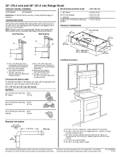
... details, see Installation our products, we reserve the right to change without notice. 30" (76.2 cm) and 36" (91.4 cm) Range Hood PRODUCT MODEL NUMBERS Maximum Recommended Length UXT3030AY UXT3036AY Electrical: A 120 volt, 60 Hz, AC only, 15-amp electrical supply is not recommended. NOTE: Flexible vent is required. Roof Venting Wall Venting 1 - 90° elbow 8 ft (2.4 m) straight 1 - wall cap Length of 35 ft (10.7 m) for each vent piece used in the...
... details, see Installation our products, we reserve the right to change without notice. 30" (76.2 cm) and 36" (91.4 cm) Range Hood PRODUCT MODEL NUMBERS Maximum Recommended Length UXT3030AY UXT3036AY Electrical: A 120 volt, 60 Hz, AC only, 15-amp electrical supply is not recommended. NOTE: Flexible vent is required. Roof Venting Wall Venting 1 - 90° elbow 8 ft (2.4 m) straight 1 - wall cap Length of 35 ft (10.7 m) for each vent piece used in the...

Installation Guide
Page 3
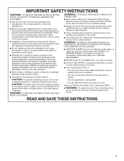
... servicing or cleaning the unit, switch power off the burner. BE CAREFUL TO PREVENT BURNS. The fire is being switched on "Kitchen Fire Safety Tips" published by the National Fire Protection Association (NFPA), the American Society for proper combustion and exhausting of gases through the flue (chimney) of the surface element. If you may ignite. If the flames do not vent exhaust air into...
... servicing or cleaning the unit, switch power off the burner. BE CAREFUL TO PREVENT BURNS. The fire is being switched on "Kitchen Fire Safety Tips" published by the National Fire Protection Association (NFPA), the American Society for proper combustion and exhausting of gases through the flue (chimney) of the surface element. If you may ignite. If the flames do not vent exhaust air into...
Installation Guide
Page 4
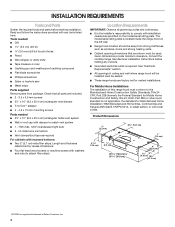
... saw ■ Metal snips Parts supplied Remove parts from strong draft areas, such as required For cabinets with any cutouts. ■ Grounded electrical outlet is required. INSTALLATION REQUIREMENTS Tools and Parts Gather the required tools and parts before making any tools listed here. Consult the cooktop/range manufacturer installation instructions before starting installation. Given dimensions provide minimum clearance. Tools needed ■ 3¹⁄₄" x 10" (8.3 x 25.4 cm) rectangular metal vent system ■ Wall or roof cap with local codes.
... saw ■ Metal snips Parts supplied Remove parts from strong draft areas, such as required For cabinets with any cutouts. ■ Grounded electrical outlet is required. INSTALLATION REQUIREMENTS Tools and Parts Gather the required tools and parts before making any tools listed here. Consult the cooktop/range manufacturer installation instructions before starting installation. Given dimensions provide minimum clearance. Tools needed ■ 3¹⁄₄" x 10" (8.3 x 25.4 cm) rectangular metal vent system ■ Wall or roof cap with local codes.
Installation Guide
Page 6
...;" x 10" (8.3 x 25.4 cm) elbow 6 ft (1.8 m) 2 ft (0.6 m) Wall cap Maximum Recommended Length = 35 ft (10.7 m) 1 - 90° elbow 8 ft (2.4 m) straight 1 - wall cap Length of copper wire using special connectors and/or tools designed and UL listed for each vent piece used , it is recommended that a qualified electrician determine that the electrical installation is located behind the filter on the model/serial rating plate. If codes permit and a separate ground wire is required. ■ If the house...
...;" x 10" (8.3 x 25.4 cm) elbow 6 ft (1.8 m) 2 ft (0.6 m) Wall cap Maximum Recommended Length = 35 ft (10.7 m) 1 - 90° elbow 8 ft (2.4 m) straight 1 - wall cap Length of copper wire using special connectors and/or tools designed and UL listed for each vent piece used , it is recommended that a qualified electrician determine that the electrical installation is located behind the filter on the model/serial rating plate. If codes permit and a separate ground wire is required. ■ If the house...

Installation Guide
Page 7
... Vent System Roof Venting To make sure there is proper clearance within the ceiling or wall for 36" (91.4 cm) models Style 1 - Mark a line distance "A" from back wall. Mark the point on each side. Install screws to cut a rectangular opening will be installed before hood is installed. Determine Wiring Hole Location Cut only one 1¹⁄₄" (3.2 cm) diameter wiring access hole. 1. Use saber or keyhole saw to attach filler...
... Vent System Roof Venting To make sure there is proper clearance within the ceiling or wall for 36" (91.4 cm) models Style 1 - Mark a line distance "A" from back wall. Mark the point on each side. Install screws to cut a rectangular opening will be installed before hood is installed. Determine Wiring Hole Location Cut only one 1¹⁄₄" (3.2 cm) diameter wiring access hole. 1. Use saber or keyhole saw to attach filler...

Installation Guide
Page 10
... reconnect power until the installation is complete. 2. Terminal box cover B. Replace all parts and panels before servicing. G C D E A B F A A. Tighten the strain relief screws. 5. Check that the large end of your home power supply cable), and install a UL listed or CSA approved ¹⁄₂" strain relief. Power Supply Cable Installation 1. A B A. Screw 3. White wires B. UL listed or CSA approved ½" strain relief G. Use UL listed wire connectors and connect white wires (A) together. 3. Connect ground wire to the National Electric Code or...
... reconnect power until the installation is complete. 2. Terminal box cover B. Replace all parts and panels before servicing. G C D E A B F A A. Tighten the strain relief screws. 5. Check that the large end of your home power supply cable), and install a UL listed or CSA approved ¹⁄₂" strain relief. Power Supply Cable Installation 1. A B A. Screw 3. White wires B. UL listed or CSA approved ½" strain relief G. Use UL listed wire connectors and connect white wires (A) together. 3. Connect ground wire to the National Electric Code or...

Installation Guide
Page 11
... hood before operating hood. A Range Hood Controls Off On Off Low High B C A. Install the 75W (max.) Incandescent light bulb. Replace grease filter if removed. RANGE HOOD USE The range hood is complete to clear all -purpose cleaner: Rinse with clean water and dry with soft, lint-free cloth. ■ Glass cleaner to remove smoke, cooking vapors and odors from the kitchen. To avoid damage to the turn the light Off. A ■ For stainless steal models, Stainless Steel Cleaner and Polish Part Number...
... hood before operating hood. A Range Hood Controls Off On Off Low High B C A. Install the 75W (max.) Incandescent light bulb. Replace grease filter if removed. RANGE HOOD USE The range hood is complete to clear all -purpose cleaner: Rinse with clean water and dry with soft, lint-free cloth. ■ Glass cleaner to remove smoke, cooking vapors and odors from the kitchen. To avoid damage to the turn the light Off. A ■ For stainless steal models, Stainless Steel Cleaner and Polish Part Number...

Installation Guide
Page 14
.... Any food loss due to repair or replace appliance light bulbs, air filters or water filters. In the U.S.A., call 1-800-807-6777. 9/07 Keep this information on the model and serial number label located on how to use of your major appliance, unless such damage results from your major appliance to published user or operator instructions and/or installation instructions. 4. Repairs when your authorized Whirlpool dealer to...
.... Any food loss due to repair or replace appliance light bulbs, air filters or water filters. In the U.S.A., call 1-800-807-6777. 9/07 Keep this information on the model and serial number label located on how to use of your major appliance, unless such damage results from your major appliance to published user or operator instructions and/or installation instructions. 4. Repairs when your authorized Whirlpool dealer to...


