

Installation Guide
Page 1
...website at www.whirlpool.ca HOTTE D'ASPIRATION DE 30" (76,2 CM) ET 36" (91,4 CM) Instructions d'installation et Guide d'utilisation et d'entretien Au Canada, pour assistance, installation ou service, composer le 1-800-807-6777 ou visiter notre site Web à www.whirlpool.ca Table of ...Contents/Table des matières 2 Models/Modèles: UXT4230AY/UXT4236AY IMPORTANT: READ AND SAVE THESE INSTRUCTIONS. IMPORTANT : ...
...website at www.whirlpool.ca HOTTE D'ASPIRATION DE 30" (76,2 CM) ET 36" (91,4 CM) Instructions d'installation et Guide d'utilisation et d'entretien Au Canada, pour assistance, installation ou service, composer le 1-800-807-6777 ou visiter notre site Web à www.whirlpool.ca Table of ...Contents/Table des matières 2 Models/Modèles: UXT4230AY/UXT4236AY IMPORTANT: READ AND SAVE THESE INSTRUCTIONS. IMPORTANT : ...

Installation Guide
Page 2
... follow instructions. TABLE OF CONTENTS RANGE HOOD SAFETY 2 INSTALLATION REQUIREMENTS 4 Tools and Parts 4 Location Requirements 4 Venting Requirements 5 Electrical Requirements 6 INSTALLATION INSTRUCTIONS 7 Prepare Location 7 Install Range Hood 9 Make Electrical Connection 11 Complete Installation 11 RANGE HOOD USE 11 Range Hood Controls 11 RANGE...TABLE DES MATIÈRES SÉCURITÉ DE LA HOTTE DE CUISINIÈRE 17 EXIGENCES D'INSTALLATION 19 Outils et pièces 19 Exigences d'emplacement 19 Exigences concernant l'évacuation 20 Spécifications é...
... follow instructions. TABLE OF CONTENTS RANGE HOOD SAFETY 2 INSTALLATION REQUIREMENTS 4 Tools and Parts 4 Location Requirements 4 Venting Requirements 5 Electrical Requirements 6 INSTALLATION INSTRUCTIONS 7 Prepare Location 7 Install Range Hood 9 Make Electrical Connection 11 Complete Installation 11 RANGE HOOD USE 11 Range Hood Controls 11 RANGE...TABLE DES MATIÈRES SÉCURITÉ DE LA HOTTE DE CUISINIÈRE 17 EXIGENCES D'INSTALLATION 19 Outils et pièces 19 Exigences d'emplacement 19 Exigences concernant l'évacuation 20 Spécifications é...
Installation Guide
Page 3
... being switched on low or medium settings. ■ Always turn off at service panel and lock the service disconnecting means to the service panel. ■ Installation work and electrical wiring must always be allowed to prevent backdrafting. Crepes Suzette, Cherries Jubilee, Peppercorn Beef Flambé). ■ Clean ventilating fans frequently. You...
... being switched on low or medium settings. ■ Always turn off at service panel and lock the service disconnecting means to the service panel. ■ Installation work and electrical wiring must always be allowed to prevent backdrafting. Crepes Suzette, Cherries Jubilee, Peppercorn Beef Flambé). ■ Clean ventilating fans frequently. You...

Installation Guide
Page 4
.... ■ These range hoods are shown must be used. For information on the model/serial rating plate. Consult the cooktop/range manufacturer installation instructions before starting installation. Models that are included. ■ 2 - 3.5 x 9.5 mm screws ■ 3¹⁄₄" x 10" (8.3 x ... screws Parts needed ■ Drill ■ 1¹⁄₄" (3.0 cm) drill bit 3.0 mm) drill bit for Manufactured Home Installation 1982 (Manufactured Home Sites, Communities and Setups) ANSI A225.1/NFPA 501A, or latest edition, or with damper to the Manufactured Home Construction...
.... ■ These range hoods are shown must be used. For information on the model/serial rating plate. Consult the cooktop/range manufacturer installation instructions before starting installation. Models that are included. ■ 2 - 3.5 x 9.5 mm screws ■ 3¹⁄₄" x 10" (8.3 x ... screws Parts needed ■ Drill ■ 1¹⁄₄" (3.0 cm) drill bit 3.0 mm) drill bit for Manufactured Home Installation 1982 (Manufactured Home Sites, Communities and Setups) ANSI A225.1/NFPA 501A, or latest edition, or with damper to the Manufactured Home Construction...

Installation Guide
Page 5
...base cabinet height Venting Requirements ■ Vent system must have a damper. The break should be on your HVAC professional for nonvented (recirculating) installations. ■ Do not terminate the vent system in an attic or other enclosed area. ■ Do not use of makeup air systems ... minimize conduction of elbows should be kept to a minimum to seal exterior wall or roof opening around the cap. Consult your installation requirements. Installation Clearances C B D A E A. 18" (45.7 cm) min. Use 3¹⁄₄" x 10" (8.3 x 25.4 cm) rectangular with a maximum vent ...
...base cabinet height Venting Requirements ■ Vent system must have a damper. The break should be on your HVAC professional for nonvented (recirculating) installations. ■ Do not terminate the vent system in an attic or other enclosed area. ■ Do not use of makeup air systems ... minimize conduction of elbows should be kept to a minimum to seal exterior wall or roof opening around the cap. Consult your installation requirements. Installation Clearances C B D A E A. 18" (45.7 cm) min. Use 3¹⁄₄" x 10" (8.3 x 25.4 cm) rectangular with a maximum vent ...

Installation Guide
Page 6
... of the system you need, add the equivalent feet (meters) for each vent piece used , it is recommended that a qualified electrician determine that the electrical installation is adequate and in the system. 7" (17.8 cm) Round Vent System Vent Piece Round 45° elbow 2.5 ft (0.8 m) 90° elbow 5.0 ft (1.5 m) 7" (17.8 cm) wall...
... of the system you need, add the equivalent feet (meters) for each vent piece used , it is recommended that a qualified electrician determine that the electrical installation is adequate and in the system. 7" (17.8 cm) Round Vent System Vent Piece Round 45° elbow 2.5 ft (0.8 m) 90° elbow 5.0 ft (1.5 m) 7" (17.8 cm) wall...

Installation Guide
Page 7
... wire to use: roof, wall or non-vented (recirculating). 3. Select a flat surface for exhaust vent. 1. The model/serial plate is installed. A A. Mark the point on the model/serial rating plate. Before making cutouts, make sure there is 2.2 cm) from back wall. ... centerline on the underside of copper wire using special connectors and/or tools designed and UL listed for 36" (91.4 cm) models 7 Disconnect power. 2. Install screws to aluminum. Depending on this point. 3" (7.6 cm) Wall ⁷⁄₈" (2.2 cm) A Centerline A. 8³⁄₈" (21.3 cm...
... wire to use: roof, wall or non-vented (recirculating). 3. Select a flat surface for exhaust vent. 1. The model/serial plate is installed. A A. Mark the point on the model/serial rating plate. Before making cutouts, make sure there is 2.2 cm) from back wall. ... centerline on the underside of copper wire using special connectors and/or tools designed and UL listed for 36" (91.4 cm) models 7 Disconnect power. 2. Install screws to aluminum. Depending on this point. 3" (7.6 cm) Wall ⁷⁄₈" (2.2 cm) A Centerline A. 8³⁄₈" (21.3 cm...

Installation Guide
Page 9
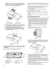
... of the 4 keyhole mounting slots on the inside of the range hood. 1. Remove top rectangular and round vent knockouts. For roof installations, remove the top rectangular vent knockout. Do not remove any knockouts. 6. A B C D A. E A. 7" (17.8 cm...accessory. A 5. For information on the inside your range hood. Complete venting system according to range hood 3.5 x 9.5 mm screws provided. Install Vent System 1. A B C A. Round vent knockout B. Install 7" (17.8 cm) round vent mounting plate or 3¼" x 10" (8.3 x 25.4 cm) vent damper, depending on ordering, see...
... of the 4 keyhole mounting slots on the inside of the range hood. 1. Remove top rectangular and round vent knockouts. For roof installations, remove the top rectangular vent knockout. Do not remove any knockouts. 6. A B C D A. E A. 7" (17.8 cm...accessory. A 5. For information on the inside your range hood. Complete venting system according to range hood 3.5 x 9.5 mm screws provided. Install Vent System 1. A B C A. Round vent knockout B. Install 7" (17.8 cm) round vent mounting plate or 3¼" x 10" (8.3 x 25.4 cm) vent damper, depending on ordering, see...
Installation Guide
Page 10
.... Remove terminal box cover and set aside. C A. A B A HG F A. Damper flap 10 A. Horizontal damper ■ If a vent damper is installed with a wall cap with damper, check that the large end of the keyhole slots are in the hood electrical terminal box. Remove the two screws...wire and slide it out of the other . A B A. Terminal box cover B. Bend the stop tab. 7. For optional power supply cord kit installations, follow the instructions in the terminal box. Screw 3. Plastic end caps D. Discard the retainer wire, plastic end caps, damper flap and the foam. ...
.... Remove terminal box cover and set aside. C A. A B A HG F A. Damper flap 10 A. Horizontal damper ■ If a vent damper is installed with a wall cap with damper, check that the large end of the keyhole slots are in the hood electrical terminal box. Remove the two screws...wire and slide it out of the other . A B A. Terminal box cover B. Bend the stop tab. 7. For optional power supply cord kit installations, follow the instructions in the terminal box. Screw 3. Plastic end caps D. Discard the retainer wire, plastic end caps, damper flap and the foam. ...
Installation Guide
Page 11
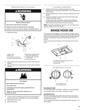
... relief G. Use UL listed wire connectors and connect black wires (B) together. WARNING B C A. Grease filter retainer C. Turn the light switch to the right 1 position for High. Install the 75W (max.) Incandescent light bulb. The hood controls are located on the front panel of the range hood fan and light. Green (or bare... left to clear all parts and panels before operating. See the "Range Hood Care" section. 3. For best results, start the hood before servicing. Black wires C. Install terminal box cover. 6. Failure to green ground screw in the "Range Hood Care" section. 2.
... relief G. Use UL listed wire connectors and connect black wires (B) together. WARNING B C A. Grease filter retainer C. Turn the light switch to the right 1 position for High. Install the 75W (max.) Incandescent light bulb. The hood controls are located on the front panel of the range hood fan and light. Green (or bare... left to clear all parts and panels before operating. See the "Range Hood Care" section. 3. For best results, start the hood before servicing. Black wires C. Install terminal box cover. 6. Failure to green ground screw in the "Range Hood Care" section. 2.

Installation Guide
Page 12
...clean water and dry with normal use. Replace screw in the channel at rear of grain to remove fingerprints. AB For vented installations: 1. Filter retainer 3. A. Light bulb socket B. Replace lens cover by placing the back edge in the grease filter retainer... hood and grease filters frequently according to release filter. Replace grease filter before calling service. 12 For non-vented (recirculating) installations: The charcoal filter is inserted correctly before operating hood. For information on ordering, see the "Accessories" section. Disconnect power....
...clean water and dry with normal use. Replace screw in the channel at rear of grain to remove fingerprints. AB For vented installations: 1. Filter retainer 3. A. Light bulb socket B. Replace lens cover by placing the back edge in the grease filter retainer... hood and grease filters frequently according to release filter. Replace grease filter before calling service. 12 For non-vented (recirculating) installations: The charcoal filter is inserted correctly before operating hood. For information on ordering, see the "Accessories" section. Disconnect power....
Installation Guide
Page 14
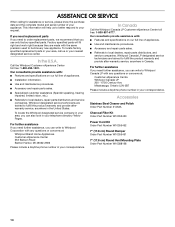
ASSISTANCE OR SERVICE When calling for assistance or service, please know the purchase date and the complete model and serial number of appliances. ■ Installation information. ■ Use and maintenance procedures. ■ Accessory and repair parts sales. ■ Specialized customer assistance (Spanish speaking, hearing impaired, limited vision, etc.). ■ Referrals ...
ASSISTANCE OR SERVICE When calling for assistance or service, please know the purchase date and the complete model and serial number of appliances. ■ Installation information. ■ Use and maintenance procedures. ■ Accessory and repair parts sales. ■ Specialized customer assistance (Spanish speaking, hearing impaired, limited vision, etc.). ■ Referrals ...

Installation Guide
Page 15
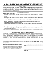
... 15 This limited warranty is valid only in materials or workmanship and is contrary to published user or operator instructions and/or installation instructions. 4. Consumable parts are excluded from your major appliance to better help by checking the "Assistance or Service" section or...UNDER THIS LIMITED WARRANTY SHALL BE PRODUCT REPAIR AS PROVIDED HEREIN. You will pay for future reference. Service calls to correct the installation of your major appliance is located in materials or workmanship. Cosmetic damage, including scratches, dents, chips or other than normal, ...
... 15 This limited warranty is valid only in materials or workmanship and is contrary to published user or operator instructions and/or installation instructions. 4. Consumable parts are excluded from your major appliance to better help by checking the "Assistance or Service" section or...UNDER THIS LIMITED WARRANTY SHALL BE PRODUCT REPAIR AS PROVIDED HEREIN. You will pay for future reference. Service calls to correct the installation of your major appliance is located in materials or workmanship. Cosmetic damage, including scratches, dents, chips or other than normal, ...

Dimension Guide
Page 1
...the equivalent feet (meters) for each vent piece used in the system. 7" (17.8 cm) Round Vent System Vent Piece Round 45° elbow 2.5 ft (0.8 m) Installation Clearances C B D A E 90° elbow 5.0 ft (1.5 m) 7" (17.8 cm) wall cap 0.0 ft (0.0 m) Because Whirlpool Corporation policy includes a continuous ... the wall or out the top (purchased separately) B. 30" (76.2 cm) and 36" (91.4 cm) Range Hood PRODUCT MODEL NUMBERS UXT4230AY UXT4236AY Electrical: q A 120 volt, 60 Hz., AC only, 15-amp, fused electrical circuit is not recommended. q Wire sizes and connections...
...the equivalent feet (meters) for each vent piece used in the system. 7" (17.8 cm) Round Vent System Vent Piece Round 45° elbow 2.5 ft (0.8 m) Installation Clearances C B D A E 90° elbow 5.0 ft (1.5 m) 7" (17.8 cm) wall cap 0.0 ft (0.0 m) Because Whirlpool Corporation policy includes a continuous ... the wall or out the top (purchased separately) B. 30" (76.2 cm) and 36" (91.4 cm) Range Hood PRODUCT MODEL NUMBERS UXT4230AY UXT4236AY Electrical: q A 120 volt, 60 Hz., AC only, 15-amp, fused electrical circuit is not recommended. q Wire sizes and connections...
Warranty Information
Page 1
...This limited warranty does not cover: 1. Damage resulting from accident, alteration, misuse, abuse, fire, flood, acts of God, improper installation, installation not in which it is designed to better help by checking the "Assistance or Service" section or by Whirlpool. 5. IMPLIED WARRANTIES...your major appliance if it . The removal and reinstallation of your major appliance. Service must provide proof of purchase or installation date for repairs. Service calls to the appliance. 9. WHIRLPOOL CORPORATION MAJOR APPLIANCE WARRANTY LIMITED WARRANTY For one year from ...
...This limited warranty does not cover: 1. Damage resulting from accident, alteration, misuse, abuse, fire, flood, acts of God, improper installation, installation not in which it is designed to better help by checking the "Assistance or Service" section or by Whirlpool. 5. IMPLIED WARRANTIES...your major appliance if it . The removal and reinstallation of your major appliance. Service must provide proof of purchase or installation date for repairs. Service calls to the appliance. 9. WHIRLPOOL CORPORATION MAJOR APPLIANCE WARRANTY LIMITED WARRANTY For one year from ...

Use & Care Guide
Page 1
...201;SIDENTIELLE UNIQUEMENT. LI3Z4B/W10400322C IMPORTANT : LIRE ET CONSERVER CES INSTRUCTIONS. 30" (76.2 CM) AND 36" (91.4 CM) RANGE HOOD Installation Instructions and Use & Care Guide For questions about features, operation/performance, parts, accessories or service, call: 1-800-253-1301 or visit our ... website at www.whirlpool.ca HOTTE D'ASPIRATION DE 30" (76,2 CM) ET 36" (91,4 CM) Instructions d'installation et Guide d'utilisation et d'entretien Au Canada, pour assistance, installation ou service, composer le 1-800-807-6777 ou visiter notre site Web à www.whirlpool.ca Table of Contents/...
...201;SIDENTIELLE UNIQUEMENT. LI3Z4B/W10400322C IMPORTANT : LIRE ET CONSERVER CES INSTRUCTIONS. 30" (76.2 CM) AND 36" (91.4 CM) RANGE HOOD Installation Instructions and Use & Care Guide For questions about features, operation/performance, parts, accessories or service, call: 1-800-253-1301 or visit our ... website at www.whirlpool.ca HOTTE D'ASPIRATION DE 30" (76,2 CM) ET 36" (91,4 CM) Instructions d'installation et Guide d'utilisation et d'entretien Au Canada, pour assistance, installation ou service, composer le 1-800-807-6777 ou visiter notre site Web à www.whirlpool.ca Table of Contents/...

Use & Care Guide
Page 2
... 14 WARRANTY 15 TABLE DES MATIÈRES SÉCURITÉ DE LA HOTTE DE CUISINIÈRE 17 EXIGENCES D'INSTALLATION 19 Outils et pièces 19 Exigences d'emplacement 19 Exigences concernant l'évacuation 20 Spécifications électriques 22 INSTRUCTIONS... D'INSTALLATION 22 Préparation de l'emplacement 22 Installation de la hotte 24 Raccordement électrique 27 Achever l'installation 27 UTILISATION DE LA HOTTE 27 Commandes de la hotte de cuisinière 27...
... 14 WARRANTY 15 TABLE DES MATIÈRES SÉCURITÉ DE LA HOTTE DE CUISINIÈRE 17 EXIGENCES D'INSTALLATION 19 Outils et pièces 19 Exigences d'emplacement 19 Exigences concernant l'évacuation 20 Spécifications électriques 22 INSTRUCTIONS... D'INSTALLATION 22 Préparation de l'emplacement 22 Installation de la hotte 24 Raccordement électrique 27 Achever l'installation 27 UTILISATION DE LA HOTTE 27 Commandes de la hotte de cuisinière 27...

Use & Care Guide
Page 3
... being switched on low or medium settings. ■ Always turn off at service panel and lock the service disconnecting means to the service panel. ■ Installation work and electrical wiring must always be sure to an authorized service facility for the size of fire and to properly exhaust air, be vented...
... being switched on low or medium settings. ■ Always turn off at service panel and lock the service disconnecting means to the service panel. ■ Installation work and electrical wiring must always be sure to an authorized service facility for the size of fire and to properly exhaust air, be vented...

Use & Care Guide
Page 4
... filters. For information on the model/serial rating plate. Location Requirements IMPORTANT: Observe all parts are capable of being installed as windows, doors and strong heating vents. ■ Cabinet opening dimensions that all governing codes and ordinances. ■.... ■ Range hood location should be used. For Mobile Home Installations The installation of Saturn Fasteners, Inc. 4 Consult the cooktop/range manufacturer installation instructions before starting installation. INSTALLATION REQUIREMENTS Tools and Parts Gather the required tools and parts before making ...
... filters. For information on the model/serial rating plate. Location Requirements IMPORTANT: Observe all parts are capable of being installed as windows, doors and strong heating vents. ■ Cabinet opening dimensions that all governing codes and ordinances. ■.... ■ Range hood location should be used. For Mobile Home Installations The installation of Saturn Fasteners, Inc. 4 Consult the cooktop/range manufacturer installation instructions before starting installation. INSTALLATION REQUIREMENTS Tools and Parts Gather the required tools and parts before making ...

Use & Care Guide
Page 5
... both back pressure and air turbulence that greatly reduce performance. above the cooking surface 5 clearance - The damper should be installed to minimize conduction of outside temperatures as possible to the outdoors, except for vent system. The specified CFM varies from the.... If roof or wall cap has a damper, remove the damper flap from locale to provide efficient performance. Cold Weather Installations An additional back draft damper should be installed to 24" (61.0 cm) suggested max. - NOTE: Flexible vent is not recommended. cabinet width for 36" (...
... both back pressure and air turbulence that greatly reduce performance. above the cooking surface 5 clearance - The damper should be installed to minimize conduction of outside temperatures as possible to the outdoors, except for vent system. The specified CFM varies from the.... If roof or wall cap has a damper, remove the damper flap from locale to provide efficient performance. Cold Weather Installations An additional back draft damper should be installed to 24" (61.0 cm) suggested max. - NOTE: Flexible vent is not recommended. cabinet width for 36" (...
