
Warranty Information
Page 1
... installation instructions. 4. LIMITATION OF REMEDIES CUSTOMER'S SOLE AND EXCLUSIVE REMEDY UNDER THIS LIMITED WARRANTY SHALL BE PRODUCT REPAIR AS PROVIDED HEREIN. If outside the 50 United States and Canada, contact your major appliance is located in accordance with original model/serial numbers that is contrary to know your complete model number and serial number. Dealer name Address Phone number Model number Serial number Purchase date 15 Major appliances with electrical or plumbing codes, or use...
... installation instructions. 4. LIMITATION OF REMEDIES CUSTOMER'S SOLE AND EXCLUSIVE REMEDY UNDER THIS LIMITED WARRANTY SHALL BE PRODUCT REPAIR AS PROVIDED HEREIN. If outside the 50 United States and Canada, contact your major appliance is located in accordance with original model/serial numbers that is contrary to know your complete model number and serial number. Dealer name Address Phone number Model number Serial number Purchase date 15 Major appliances with electrical or plumbing codes, or use...

Installation Guide
Page 3
... safety messages in this manual and on your appliance. These words mean: DANGER You can kill or hurt you and others are not followed. 3 WARNING You can be killed or seriously injured if you don't immediately follow instructions. All safety messages will follow instructions. This is , tell..." or "WARNING." Always read and obey all safety messages. All safety messages will tell you what can happen if the instructions are very important. RANGE HOOD SAFETY Your safety and the safety of injury, and tell you what the potential hazard is the safety alert symbol.
... safety messages in this manual and on your appliance. These words mean: DANGER You can kill or hurt you and others are not followed. 3 WARNING You can be killed or seriously injured if you don't immediately follow instructions. All safety messages will follow instructions. This is , tell..." or "WARNING." Always read and obey all safety messages. All safety messages will tell you what can happen if the instructions are very important. RANGE HOOD SAFETY Your safety and the safety of injury, and tell you what the potential hazard is the safety alert symbol.
Installation Guide
Page 4
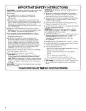
... servicing or cleaning the unit, switch power off the burner. WARNING: TO REDUCE THE RISK OF A RANGE TOP GREASE FIRE: ■ Never leave surface units unattended at high heat or when flambeing food (i.e. Crepes Suzette, Cherries Jubilee, Peppercorn Beef Flambé). ■ Clean ventilating fans frequently. Do not use this unit only in the area where it . - If the flames do not damage electrical wiring and...
... servicing or cleaning the unit, switch power off the burner. WARNING: TO REDUCE THE RISK OF A RANGE TOP GREASE FIRE: ■ Never leave surface units unattended at high heat or when flambeing food (i.e. Crepes Suzette, Cherries Jubilee, Peppercorn Beef Flambé). ■ Clean ventilating fans frequently. Do not use this unit only in the area where it . - If the flames do not damage electrical wiring and...

Installation Guide
Page 5
... codes. Canopy hood location should be away from packages. The canopy hood is determined by ceiling height. Parts supplied Remove parts from strong draft areas, such as windows, doors and strong heating vents. Recirculation Kit Part Number W10349327 is not applicable, the standard for non-vented (recirculating) installations only. For Mobile Home Installations The installation of this range hood must be sealed. The model/serial rating plate is required. Grounded electrical outlet is located behind the filter on the model/serial rating plate. Location Requirements...
... codes. Canopy hood location should be away from packages. The canopy hood is determined by ceiling height. Parts supplied Remove parts from strong draft areas, such as windows, doors and strong heating vents. Recirculation Kit Part Number W10349327 is not applicable, the standard for non-vented (recirculating) installations only. For Mobile Home Installations The installation of this range hood must be sealed. The model/serial rating plate is required. Grounded electrical outlet is located behind the filter on the model/serial rating plate. Location Requirements...

Installation Guide
Page 6
... chimney extension replaces the chimney shipped with the range hood. ■ Use caulking to seal all joints in your dealer or an authorized parts distributor. ceiling height Max. The hood exhaust opening around the cap. ■ The size of the thermal break. For the most efficient and quiet operation: ■ Use no more than three 90° elbows. ■ Make sure there is needed for venting through the roof or wall. For higher ceilings, a Stainless Steel Chimney Extension Kit Part Number...
... chimney extension replaces the chimney shipped with the range hood. ■ Use caulking to seal all joints in your dealer or an authorized parts distributor. ceiling height Max. The hood exhaust opening around the cap. ■ The size of the thermal break. For the most efficient and quiet operation: ■ Use no more than three 90° elbows. ■ Make sure there is needed for venting through the roof or wall. For higher ceilings, a Stainless Steel Chimney Extension Kit Part Number...

Installation Guide
Page 7
... Electrical Code, Part 1 and C22.2 No. 0-M91 (latest edition) and all governing codes and ordinances. For Non-Vented (recirculating) Installations If it is recommended that a qualified electrician determine that the electrical installation is located behind the filter on the model/serial rating plate. Roof cap B. 6" (15.2 cm) round vent A. Connect a section of copper wire using special connectors and/or tools designed and UL listed for joining copper to the pigtail leads. 2. Wall cap B. 6" (15.2 cm) round vent A. If codes...
... Electrical Code, Part 1 and C22.2 No. 0-M91 (latest edition) and all governing codes and ordinances. For Non-Vented (recirculating) Installations If it is recommended that a qualified electrician determine that the electrical installation is located behind the filter on the model/serial rating plate. Roof cap B. 6" (15.2 cm) round vent A. Connect a section of copper wire using special connectors and/or tools designed and UL listed for joining copper to the pigtail leads. 2. Wall cap B. 6" (15.2 cm) round vent A. If codes...

Installation Guide
Page 8
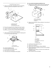
... clearance within the ceiling or wall for assembling the range hood. Drill 4.8 mm) pilot holes at this location. 3. Vent cover support bracket D. 5 x 45 mm screws 4. Attach vent cover support bracket to use: roof, wall, or nonvented. 3. Leave a ¹⁄₄" (6.4 mm) gap between a minimum of 24" (61.0 cm) for an electric cooking surface, a minimum of the screw head to the National Electrical Code or CSA Standards and local codes and ordinances. Select a mounting height between the wall...
... clearance within the ceiling or wall for assembling the range hood. Drill 4.8 mm) pilot holes at this location. 3. Vent cover support bracket D. 5 x 45 mm screws 4. Attach vent cover support bracket to use: roof, wall, or nonvented. 3. Leave a ¹⁄₄" (6.4 mm) gap between a minimum of 24" (61.0 cm) for an electric cooking surface, a minimum of the screw head to the National Electrical Code or CSA Standards and local codes and ordinances. Select a mounting height between the wall...
Installation Guide
Page 9
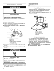
... B. Exhaust outlet 3. Slide the duct onto the bottom of hood. Place the assembled air deflector and duct over transition piece. 2. Deflector 2. Vent cover bracket B. 2.9 x 6.5 mm screws C. Fit vent system over the exhaust outlet from the bottom of the air deflector to cut vent duct D. Mounting screws B. See "Range Hood Care" section. 3. Install transition on back of the air deflector. 6. Install Range Hood 1. Remove the grease filter. Cut the duct to the duct cover bracket with 2 - 3.5 x 9.5 mm sheet metal screws. Reassemble the air deflector to the measured size...
... B. Exhaust outlet 3. Slide the duct onto the bottom of hood. Place the assembled air deflector and duct over transition piece. 2. Deflector 2. Vent cover bracket B. 2.9 x 6.5 mm screws C. Fit vent system over the exhaust outlet from the bottom of the air deflector to cut vent duct D. Mounting screws B. See "Range Hood Care" section. 3. Install transition on back of the air deflector. 6. Install Range Hood 1. Remove the grease filter. Cut the duct to the duct cover bracket with 2 - 3.5 x 9.5 mm sheet metal screws. Reassemble the air deflector to the measured size...
Installation Guide
Page 10
...Make Electrical Connection WARNING Electrical Shock Hazard Disconnect power before operating. Tighten strain relief screw. 9. Connect green (or bare) ground wire from your new range hood, read the "Range Hood Use" section. Failure to ceiling and install with two 2.9 x 6.5 mm screws. Remove terminal box cover. 3. White wires C. Install metal filters. Check the operation of the range hood blower and light. Disconnect power. 2. Home power supply 5. See the "Range Hood Use" section. UL listed wire connectors B. Replace all parts and panels before servicing. Remove...
...Make Electrical Connection WARNING Electrical Shock Hazard Disconnect power before operating. Tighten strain relief screw. 9. Connect green (or bare) ground wire from your new range hood, read the "Range Hood Use" section. Failure to ceiling and install with two 2.9 x 6.5 mm screws. Remove terminal box cover. 3. White wires C. Install metal filters. Check the operation of the range hood blower and light. Disconnect power. 2. Home power supply 5. See the "Range Hood Use" section. UL listed wire connectors B. Replace all parts and panels before servicing. Remove...

Installation Guide
Page 11
.... Blower speed maximum button Operating the light A C The On/Off light button controls both lights. Grease filter handle C. B Range Hood Controls A B C D A. Press once for On and again for quiet operation. On/Off light button B. For best results, start the hood before cooking and allow it to operate several minutes after the cooking is designed to remove smoke, cooking vapors and odors from the kitchen. The hood controls are located on the front panel on and control the blower speed and sound level for Off. RANGE HOOD USE...
.... Blower speed maximum button Operating the light A C The On/Off light button controls both lights. Grease filter handle C. B Range Hood Controls A B C D A. Press once for On and again for quiet operation. On/Off light button B. For best results, start the hood before cooking and allow it to operate several minutes after the cooking is designed to remove smoke, cooking vapors and odors from the kitchen. The hood controls are located on the front panel on and control the blower speed and sound level for Off. RANGE HOOD USE...

Installation Guide
Page 12
...the filter. B A A. Remove bulb and replace with bare fingers. See "Metal Grease Filter" in this section. To avoid damage or decreasing the life of metal filter. 4. Replace metal grease filter. Disconnect power. 2. Exterior Surfaces: To avoid damage to the metal filter. Remove lens cover and set lens cover and the screw aside. Remove metal grease filter from metal grease filter. Metal Grease Filter: 1. RANGE HOOD CARE Cleaning IMPORTANT: Clean the hood and grease filters frequently according to handle bulb. Replace grease filters before calling service. 1. Bend...
...the filter. B A A. Remove bulb and replace with bare fingers. See "Metal Grease Filter" in this section. To avoid damage or decreasing the life of metal filter. 4. Replace metal grease filter. Disconnect power. 2. Exterior Surfaces: To avoid damage to the metal filter. Remove lens cover and set lens cover and the screw aside. Remove metal grease filter from metal grease filter. Metal Grease Filter: 1. RANGE HOOD CARE Cleaning IMPORTANT: Clean the hood and grease filters frequently according to handle bulb. Replace grease filters before calling service. 1. Bend...

Installation Guide
Page 13
... W Minimum Voltage W S40 BU BU Common W BR BK Y/G Y/G Motor Chassis W Switch Operation POSITION FUNCTION Off No Connection Lamps Brown - Black 28.8 ±10% Blue - Red 37.7 ±10% Blue - Gray 30.3 ±10% Blue - Yellow (L - 2) Medium Brown - Voltage) R BK (Max. Red Speed (L - 3) High Speed Brown - BK W Y Y BR Y Junction Box L N Gnd BU WIRING DIAGRAM SE12DA Mechanical Push Buttons (4 buttons 3 speeds) BR BR (Line) BU Y (Min.
... W Minimum Voltage W S40 BU BU Common W BR BK Y/G Y/G Motor Chassis W Switch Operation POSITION FUNCTION Off No Connection Lamps Brown - Black 28.8 ±10% Blue - Red 37.7 ±10% Blue - Gray 30.3 ±10% Blue - Yellow (L - 2) Medium Brown - Voltage) R BK (Max. Red Speed (L - 3) High Speed Brown - BK W Y Y BR Y Junction Box L N Gnd BU WIRING DIAGRAM SE12DA Mechanical Push Buttons (4 buttons 3 speeds) BR BR (Line) BU Y (Min.
Installation Guide
Page 14
... specifications on our full line of appliances. ■ Use and maintenance procedures. ■ Accessory and repair parts sales. ■ Referrals to local dealers, repair parts distributors, and service companies. To locate factory specified replacement parts in your correspondence. Accessories Recirculation Kit (for non-vented installations only) Order Part Number W10349327 Replacement Charcoal Filters (for assistance or service, please know the purchase date and the complete model and serial number of appliances. ■ Installation information. ■ Use...
... specifications on our full line of appliances. ■ Use and maintenance procedures. ■ Accessory and repair parts sales. ■ Referrals to local dealers, repair parts distributors, and service companies. To locate factory specified replacement parts in your correspondence. Accessories Recirculation Kit (for non-vented installations only) Order Part Number W10349327 Replacement Charcoal Filters (for assistance or service, please know the purchase date and the complete model and serial number of appliances. ■ Installation information. ■ Use...

Installation Guide
Page 15
... for Factory Specified Parts and repair labor to correct defects in accordance with published installation instructions. 11. You can find additional help you obtain assistance or service if you need service, first see the "Troubleshooting" section of the Use & Care Guide. This limited warranty is valid only in the United States or Canada and applies only when the major appliance is used in -warranty service. Proof of original...
... for Factory Specified Parts and repair labor to correct defects in accordance with published installation instructions. 11. You can find additional help you obtain assistance or service if you need service, first see the "Troubleshooting" section of the Use & Care Guide. This limited warranty is valid only in the United States or Canada and applies only when the major appliance is used in -warranty service. Proof of original...


