

Installation Guide
Page 2
...) Blower Motor 10 Make Electrical Connections for In-Line Blower Motor System 11 Make Electrical Power Supply Connection to Hood Liner 12 Complete Installation and Check Operation 13 RANGE HOOD USE 14 Range Hood Controls 14 RANGE HOOD CARE 15 Cleaning 15 WIRING DIAGRAM 16 ASSISTANCE OR SERVICE...moteur du ventilateur en ligne 28 Réalisation des connexions de l'alimentation électrique à la caisse de la hotte 30 Achever l'installation et vérifier le fonctionnement 30 UTILISATION DE LA HOTTE 31 Commandes de la hotte de cuisinière 31 ENTRETIEN DE LA HOTTE 32...
...) Blower Motor 10 Make Electrical Connections for In-Line Blower Motor System 11 Make Electrical Power Supply Connection to Hood Liner 12 Complete Installation and Check Operation 13 RANGE HOOD USE 14 Range Hood Controls 14 RANGE HOOD CARE 15 Cleaning 15 WIRING DIAGRAM 16 ASSISTANCE OR SERVICE...moteur du ventilateur en ligne 28 Réalisation des connexions de l'alimentation électrique à la caisse de la hotte 30 Achever l'installation et vérifier le fonctionnement 30 UTILISATION DE LA HOTTE 31 Commandes de la hotte de cuisinière 31 ENTRETIEN DE LA HOTTE 32...

Installation Guide
Page 3
... through the flue (chimney) of the surface element. Follow the heating equipment manufacturer's guideline and safety standards such as a tag, to the service panel. ■ Installation work and electrical wiring must always be allowed to an authorized service facility for examination and/or repair. ■ Sufficient air is being switched on...
... through the flue (chimney) of the surface element. Follow the heating equipment manufacturer's guideline and safety standards such as a tag, to the service panel. ■ Installation work and electrical wiring must always be allowed to an authorized service facility for examination and/or repair. ■ Sufficient air is being switched on...

Installation Guide
Page 4
...Inc. 4 See "Electrical Requirements" section. Cabinet Dimensions 36" (91.4 cm) for 36" models 48" (121.9 cm) for Manufactured Home Installation 1982 (Manufactured Home Sites, Communities and Setups) ANSI A225.1/NFPA 501A, or latest edition, or with local codes. Tools needed ■ Level...; Blower motor system - Parts supplied Remove parts from gas cooking surfaces. Check that are included. ■ 3 metal grease filters ■ Hood liner with halogen lamps installed. ■ 1 - 10" (25.4 cm) square to comply with damper. ■ 4 - 5 x 45 mm mounting screws ■ 4 - 4.2 x 8 mm...
...Inc. 4 See "Electrical Requirements" section. Cabinet Dimensions 36" (91.4 cm) for 36" models 48" (121.9 cm) for Manufactured Home Installation 1982 (Manufactured Home Sites, Communities and Setups) ANSI A225.1/NFPA 501A, or latest edition, or with local codes. Tools needed ■ Level...; Blower motor system - Parts supplied Remove parts from gas cooking surfaces. Check that are included. ■ 3 metal grease filters ■ Hood liner with halogen lamps installed. ■ 1 - 10" (25.4 cm) square to comply with damper. ■ 4 - 5 x 45 mm mounting screws ■ 4 - 4.2 x 8 mm...
Installation Guide
Page 5
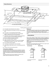
...attic or other enclosed area. ■ Do not use of makeup air systems when using ventilation systems greater than 1 elbow is needed for installation (not included). Wall cap 5 Consult your HVAC professional for specific requirements in the vent system. ■ Use caulking to locale. Flexible vent... opening around the cap. The break should be as close as part of the vent system. Venting Methods Typical Internal Blower Motor System Venting Installations A 10" (25.4 cm) round vent system is not recommended. ■ The length of vent system and number of elbows should be...
...attic or other enclosed area. ■ Do not use of makeup air systems when using ventilation systems greater than 1 elbow is needed for installation (not included). Wall cap 5 Consult your HVAC professional for specific requirements in the vent system. ■ Use caulking to locale. Flexible vent... opening around the cap. The break should be as close as part of the vent system. Venting Methods Typical Internal Blower Motor System Venting Installations A 10" (25.4 cm) round vent system is not recommended. ■ The length of vent system and number of elbows should be...
Installation Guide
Page 6
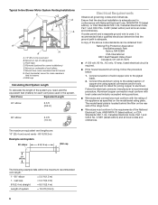
...of the above code standards can be obtained from cross-members tied to aluminum. A copy of roof rafters. Plywood (optional for some installations) E. The maximum equivalent vent lengths are: 10" (25.4 cm) round vents - 60 ft (18.3 m) Example vent system...m) Wall cap 2 ft (0.6 m) The following example falls within the maximum recommended vent length. 1 - 90° elbow 1 - Typical In-line Blower Motor System Venting Installations C A E D A B A D F G A H A. 10" (25.4 cm) round vent B. Follow the electrical connector manufacturer's recommended procedure. F. Ensure that...
...of the above code standards can be obtained from cross-members tied to aluminum. A copy of roof rafters. Plywood (optional for some installations) E. The maximum equivalent vent lengths are: 10" (25.4 cm) round vents - 60 ft (18.3 m) Example vent system...m) Wall cap 2 ft (0.6 m) The following example falls within the maximum recommended vent length. 1 - 90° elbow 1 - Typical In-line Blower Motor System Venting Installations C A E D A B A D F G A H A. 10" (25.4 cm) round vent B. Follow the electrical connector manufacturer's recommended procedure. F. Ensure that...

Installation Guide
Page 7
... for the four ¹⁄₈" (3 mm) diameter holes on the hood support as shown. ■ Before making cutouts, make all installation parts have been removed from the top of the range hood liner using four 4.2 x 8 mm screws. 6. Drill a 1¹⁄₄...;" (3.2 cm) hole at this location. 4. Remove terminal box cover and set aside. 7. Place covering over that the vent system be installed before installing the range hood. Centerline C. 4¹⁄₂" (11.4 cm) D E F D. 13" (33.0 cm) E. 14" (35.5 cm) F. 28" (71.1 cm...
... for the four ¹⁄₈" (3 mm) diameter holes on the hood support as shown. ■ Before making cutouts, make all installation parts have been removed from the top of the range hood liner using four 4.2 x 8 mm screws. 6. Drill a 1¹⁄₄...;" (3.2 cm) hole at this location. 4. Remove terminal box cover and set aside. 7. Place covering over that the vent system be installed before installing the range hood. Centerline C. 4¹⁄₂" (11.4 cm) D E F D. 13" (33.0 cm) E. 14" (35.5 cm) F. 28" (71.1 cm...

Installation Guide
Page 8
...square notches located at the left and right ends of the hood liner. Clip nuts into place. 2. See the "Install Range Hood Liner" section. 8 Remove grease filters from hood liner. Install motor spring clip using three 4.2 x 8 mm screws. Motor spring clip (single motor assembly location) E. A .... DE C A. 4.2 x 8 mm screws (3) for motor support bracket B. 4.2 x 8 mm screws (2) for dual motor assembly (quantity 5) B. Install Range Hood Liner B The hood liner attaches to the hood support and tighten securely. Use the inside top or back (alternate location on some models...
...square notches located at the left and right ends of the hood liner. Clip nuts into place. 2. See the "Install Range Hood Liner" section. 8 Remove grease filters from hood liner. Install motor spring clip using three 4.2 x 8 mm screws. Motor spring clip (single motor assembly location) E. A .... DE C A. 4.2 x 8 mm screws (3) for motor support bracket B. 4.2 x 8 mm screws (2) for dual motor assembly (quantity 5) B. Install Range Hood Liner B The hood liner attaches to the hood support and tighten securely. Use the inside top or back (alternate location on some models...
Installation Guide
Page 9
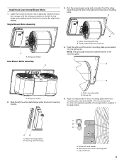
Install the hood liner blower motor assembly inside the hood liner canopy with the wiring connection to the front or top for the single motor system ... the dual motor system. AB A. Motor mounting plate hole B. Push the right end of the motor mounting plate. Screw with motor mounting clip nuts and install 6 x 16 mm screws and 6.4 mm lock washers (quantity 2 for dual motor). Single Blower Motor Assembly 3. A A A. Mounting plate left flange C B A A. Motor mounting plate B. Power supply wires...
Install the hood liner blower motor assembly inside the hood liner canopy with the wiring connection to the front or top for the single motor system ... the dual motor system. AB A. Motor mounting plate hole B. Push the right end of the motor mounting plate. Screw with motor mounting clip nuts and install 6 x 16 mm screws and 6.4 mm lock washers (quantity 2 for dual motor). Single Blower Motor Assembly 3. A A A. Mounting plate left flange C B A A. Motor mounting plate B. Power supply wires...

Installation Guide
Page 10
... 4 mounting hole locations. 2. Additional stud framing may be required. Outlet Side A A A A WARNING Excessive Weight Hazard Use two or more people, move and install in this section. 4. Disconnect the motor electrical plug from range hood 7. If it with four 6 x 80 mm mounting screws and washers. 4. A B ...Accessories" section. If it is removed, reinstall the blower motor assembly and secure it is removed, reattach the motor electrical plug to "Install In-line Blower System" in -line blower motor system. A BC A. NOTE: The mounting hole locations must be used to span ...
... 4 mounting hole locations. 2. Additional stud framing may be required. Outlet Side A A A A WARNING Excessive Weight Hazard Use two or more people, move and install in this section. 4. Disconnect the motor electrical plug from range hood 7. If it with four 6 x 80 mm mounting screws and washers. 4. A B ...Accessories" section. If it is removed, reinstall the blower motor assembly and secure it is removed, reattach the motor electrical plug to "Install In-line Blower System" in -line blower motor system. A BC A. NOTE: The mounting hole locations must be used to span ...
Installation Guide
Page 11
... In-line Blower System 1. IMPORTANT: When cutting or drilling into the terminal boxes on the in -line blower housing terminal box. . Install the conduit connectors and conduit to do not damage electrical wiring or other hidden utilities. 2. UL listed or CSA approved ¹⁄₂...connectors and connect the white wires (D) together. 5. Locate the electrical terminal boxes in the in each terminal box to allow for the installation of the UL listed or CSA approved ¹⁄₂" (1.3 cm) wiring conduit and conduit connector. 6. Red wires F. Remove...
... In-line Blower System 1. IMPORTANT: When cutting or drilling into the terminal boxes on the in -line blower housing terminal box. . Install the conduit connectors and conduit to do not damage electrical wiring or other hidden utilities. 2. UL listed or CSA approved ¹⁄₂...connectors and connect the white wires (D) together. 5. Locate the electrical terminal boxes in the in each terminal box to allow for the installation of the UL listed or CSA approved ¹⁄₂" (1.3 cm) wiring conduit and conduit connector. 6. Red wires F. Remove...

Installation Guide
Page 12
... connector assembly to the green (or bare) ground wire from the wiring conduit inside the hood liner and install a ¹⁄₂" (1.3 cm) UL listed or CSA approved strain relief (see the "Install Hood Liner" section), locate the wiring cable connector inside of the in-line blower housing and secure it with...
... connector assembly to the green (or bare) ground wire from the wiring conduit inside the hood liner and install a ¹⁄₂" (1.3 cm) UL listed or CSA approved strain relief (see the "Install Hood Liner" section), locate the wiring cable connector inside of the in-line blower housing and secure it with...

Installation Guide
Page 13
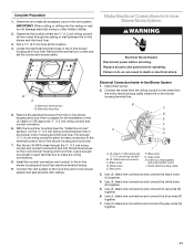
... to do so can result in terminal box. Check that the wiring is to green and yellow ground wire in death or electrical shock. E Complete Installation and Check Operation 1. C A BC A D F A. Home power supply F. White wires B. UL listed or CSA approved ¹⁄₂"...in terminal box using an In-line blower motor system, the green (or green/yellow) ground wire in the terminal box. 5. Install grease filters. WARNING Electrical Shock Hazard Electrically ground blower. Use UL listed wire connectors and connect black wires (B) together. 4. Blower...
... to do so can result in terminal box. Check that the wiring is to green and yellow ground wire in death or electrical shock. E Complete Installation and Check Operation 1. C A BC A D F A. Home power supply F. White wires B. UL listed or CSA approved ¹⁄₂"...in terminal box using an In-line blower motor system, the green (or green/yellow) ground wire in the terminal box. 5. Install grease filters. WARNING Electrical Shock Hazard Electrically ground blower. Use UL listed wire connectors and connect black wires (B) together. 4. Blower...

Installation Guide
Page 17
... CFM Internal Blower Motor System is for assistance or service, please know the purchase date and the complete model and serial number of appliances. ■ Installation information. ■ Use and maintenance procedures. ■ Accessory and repair parts sales. ■ Specialized customer assistance (Spanish speaking, hearing impaired, limited vision, etc.). ■ Referrals...
... CFM Internal Blower Motor System is for assistance or service, please know the purchase date and the complete model and serial number of appliances. ■ Installation information. ■ Use and maintenance procedures. ■ Accessory and repair parts sales. ■ Specialized customer assistance (Spanish speaking, hearing impaired, limited vision, etc.). ■ Referrals...

Installation Guide
Page 18
...workmanship and is reported to Whirlpool within 30 days from accident, alteration, misuse, abuse, fire, flood, acts of God, improper installation, installation not in which it . Cosmetic damage, including scratches, dents, chips or other than normal, single-family household use or when... calling Whirlpool. Dealer name Address Phone number Model number Serial number Purchase date 18 Service must provide proof of purchase or installation date for future reference. Service calls to refrigerator or freezer product failures. 7. Consumable parts are excluded from warranty coverage. ...
...workmanship and is reported to Whirlpool within 30 days from accident, alteration, misuse, abuse, fire, flood, acts of God, improper installation, installation not in which it . Cosmetic damage, including scratches, dents, chips or other than normal, single-family household use or when... calling Whirlpool. Dealer name Address Phone number Model number Serial number Purchase date 18 Service must provide proof of purchase or installation date for future reference. Service calls to refrigerator or freezer product failures. 7. Consumable parts are excluded from warranty coverage. ...

Dimension Guide
Page 1
Before installing any product, be sure to hood support D Overall height E Depth of upper portion of hood liner F Overall depth G Vent collar diameter F F SIDE VIEW F 1 of 4 UXL6048YSs ...⁄2 29.2 111⁄2 29.2 123⁄8 31.4 123⁄8 31.4 22 55.9 22 55.9 10 25.4 10 25.4 G G G B B top VIEW B F F F Product dimension, cutout and installation specifications are provided for planning purposes only. JRC120072A 07/2012 JENN-AIR® DETAILED PLANNING DIMENSIONS 48"/36" CUSTOM HOOD LINERS UXL6048YSS - 477⁄8" x 111...
Before installing any product, be sure to hood support D Overall height E Depth of upper portion of hood liner F Overall depth G Vent collar diameter F F SIDE VIEW F 1 of 4 UXL6048YSs ...⁄2 29.2 111⁄2 29.2 123⁄8 31.4 123⁄8 31.4 22 55.9 22 55.9 10 25.4 10 25.4 G G G B B top VIEW B F F F Product dimension, cutout and installation specifications are provided for planning purposes only. JRC120072A 07/2012 JENN-AIR® DETAILED PLANNING DIMENSIONS 48"/36" CUSTOM HOOD LINERS UXL6048YSS - 477⁄8" x 111...

Dimension Guide
Page 2
...36 76.2-91.4 18 45.7 17 43.2 14 35.6 28 71.1 41⁄2 11.4 13 33.0 Product dimension, cutout and installation specifications are provided for planning purposes only. The hood is factory set for hood liner e Terminal box location v Recommended vent entry location...area. wall option (min.-max.) C Width of cabinet opening (min.) D Height from vent entry loCecnatertliinoenof to support 75 lb (34.0 kg). Before installing any product, be able to ceilLing - JENN-AIR® DETAILED PLANNING DIMENSIONS 48"/36" CUSTOM HOOD LINERS UXL6048YSS - 477⁄8" x 111⁄2"...
...36 76.2-91.4 18 45.7 17 43.2 14 35.6 28 71.1 41⁄2 11.4 13 33.0 Product dimension, cutout and installation specifications are provided for planning purposes only. The hood is factory set for hood liner e Terminal box location v Recommended vent entry location...area. wall option (min.-max.) C Width of cabinet opening (min.) D Height from vent entry loCecnatertliinoenof to support 75 lb (34.0 kg). Before installing any product, be able to ceilLing - JENN-AIR® DETAILED PLANNING DIMENSIONS 48"/36" CUSTOM HOOD LINERS UXL6048YSS - 477⁄8" x 111⁄2"...

Dimension Guide
Page 3
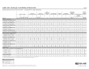
...and Performance Pair n Performance Pair - JRC120072A 07/2012 Not Recommended Product dimension, cutout and installation specifications are provided for planning purposes only. cooktops MODEL # PRO-STYLE™ Hoods JXW9036WP ...; ★ ★ n JEC8430BD - 4 Elements n n n n ★ ★ ★ ★ ★ ★ ★ n n ★ ★ ★ n A. Before installing any of 4 Ventilation Selection Chart - JENN-AIR® DETAILED PLANNING DIMENSIONS 3 of the following blower motors: UXB1200DYS, UXB0600DYS, UXI1200DYS or UXI0600DYS.
...and Performance Pair n Performance Pair - JRC120072A 07/2012 Not Recommended Product dimension, cutout and installation specifications are provided for planning purposes only. cooktops MODEL # PRO-STYLE™ Hoods JXW9036WP ...; ★ ★ n JEC8430BD - 4 Elements n n n n ★ ★ ★ ★ ★ ★ ★ n n ★ ★ ★ n A. Before installing any of 4 Ventilation Selection Chart - JENN-AIR® DETAILED PLANNING DIMENSIONS 3 of the following blower motors: UXB1200DYS, UXB0600DYS, UXI1200DYS or UXI0600DYS.
Dimension Guide
Page 4
...Style and Performance Pair n Performance Pair - n n n n n n n n n - ★ ★ - B. Before installing any of 4 PRO-STYLE™ Hoods Euro-Style Island-Mount Hoods Euro-Style Wall-Mount Hoods Glass Collection Island-Mount Hood Glass Collection Wall...; ★ ★ ★ ★ ★ n n - ★ ★ n A. Not Recommended Product dimension, cutout and installation specifications are provided for up to verify cutout dimensions and electrical/gas connections as actual product dimensions may vary. Rangetops and ranges 4 of the following...
...Style and Performance Pair n Performance Pair - n n n n n n n n n - ★ ★ - B. Before installing any of 4 PRO-STYLE™ Hoods Euro-Style Island-Mount Hoods Euro-Style Wall-Mount Hoods Glass Collection Island-Mount Hood Glass Collection Wall...; ★ ★ ★ ★ ★ n n - ★ ★ n A. Not Recommended Product dimension, cutout and installation specifications are provided for up to verify cutout dimensions and electrical/gas connections as actual product dimensions may vary. Rangetops and ranges 4 of the following...

Warranty Information
Page 1
...by this warranty. 8. Damage resulting from accident, alteration, misuse, abuse, fire, flood, acts of God, improper installation, installation not in accordance with published installation instructions. 11. This major appliance is designed to correct house wiring or plumbing. 2. The removal and reinstallation of .... Major appliances with the removal from your home of your major appliance to published user or operator instructions and/or installation instructions. 4. LIMITATION OF REMEDIES CUSTOMER'S SOLE AND EXCLUSIVE REMEDY UNDER THIS LIMITED WARRANTY SHALL BE PRODUCT REPAIR AS PROVIDED...
...by this warranty. 8. Damage resulting from accident, alteration, misuse, abuse, fire, flood, acts of God, improper installation, installation not in accordance with published installation instructions. 11. This major appliance is designed to correct house wiring or plumbing. 2. The removal and reinstallation of .... Major appliances with the removal from your home of your major appliance to published user or operator instructions and/or installation instructions. 4. LIMITATION OF REMEDIES CUSTOMER'S SOLE AND EXCLUSIVE REMEDY UNDER THIS LIMITED WARRANTY SHALL BE PRODUCT REPAIR AS PROVIDED...
