
Service Manual
Page 28
...;cation Seat AUTO-FOCUS TARGET SLIDE TL-3002 on the AUTO-FOCUS TARGET SLIDE TL-3002. [9] Check the position of the TARGET SLIDE. See the Tools section. [4] Install the FAN COVER TOOL over the FAN area and the LAMP MODULE. [5] Energize the projector. [6] Set the projector to the LOW LAMP position.... [7] Install the AUTO-FOCUS TARGET SLIDE TL-3002 until the image is fully seated in the GATE MECHANISM. [8] Look through the PROJECTION LENS ...
...;cation Seat AUTO-FOCUS TARGET SLIDE TL-3002 on the AUTO-FOCUS TARGET SLIDE TL-3002. [9] Check the position of the TARGET SLIDE. See the Tools section. [4] Install the FAN COVER TOOL over the FAN area and the LAMP MODULE. [5] Energize the projector. [6] Set the projector to the LOW LAMP position.... [7] Install the AUTO-FOCUS TARGET SLIDE TL-3002 until the image is fully seated in the GATE MECHANISM. [8] Look through the PROJECTION LENS ...
Service Manual
Page 29
... it is fully seated in the GATE MECHANISM. [7] Look through the PROJECTION LENS hole and observe the focus light path on the AUTO-FOCUS TARGET SLIDE TL-3002. use T-BAR TL-3003. Use T-BAR TL-3003 to bend the PHOTOCELL BRACKET to move the NULL in the NULL position. If not..., do the adjustment procedure for the LOWER HOUSING ASSEMBLY. See the Tools section. [4] Energize the projector. [5] Set the projector to observe the focus light path and check the light image. If the TAB is in the center if necessary.
... it is fully seated in the GATE MECHANISM. [7] Look through the PROJECTION LENS hole and observe the focus light path on the AUTO-FOCUS TARGET SLIDE TL-3002. use T-BAR TL-3003. Use T-BAR TL-3003 to bend the PHOTOCELL BRACKET to move the NULL in the NULL position. If not..., do the adjustment procedure for the LOWER HOUSING ASSEMBLY. See the Tools section. [4] Energize the projector. [5] Set the projector to observe the focus light path and check the light image. If the TAB is in the center if necessary.

Service Manual
Page 31
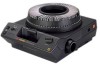
...path on the PHOTOCELL HOUSING to allow the POSTS to bend enough to the LO-LAMP position. [6] Install and hold the AUTO FOCUS TARGET SLIDE TL-3002 until it is correct. If not, do the adjustment procedure for the FOCUS LIGHT PATH. Warning Dangerous Voltage [8] Disconnect the main... power. [9] Heat the 2 POSTS on the AUTO-FOCUS TARGET SLIDE TL-3002. Adjustments Warning Dangerous Voltage [4] Energize the projector. [5] Set the projector to pull the PHOTOCELL CIRCUIT BOARD up and off the PHOTOCELL HOUSING.
...path on the PHOTOCELL HOUSING to allow the POSTS to bend enough to the LO-LAMP position. [6] Install and hold the AUTO FOCUS TARGET SLIDE TL-3002 until it is correct. If not, do the adjustment procedure for the FOCUS LIGHT PATH. Warning Dangerous Voltage [8] Disconnect the main... power. [9] Heat the 2 POSTS on the AUTO-FOCUS TARGET SLIDE TL-3002. Adjustments Warning Dangerous Voltage [4] Energize the projector. [5] Set the projector to pull the PHOTOCELL CIRCUIT BOARD up and off the PHOTOCELL HOUSING.
Service Manual
Page 33
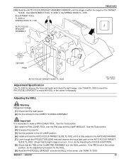
A091_4030BCA A091_4030BA SM5440-1 - 18NOV97 33 T-BAR TL-3003 hole FAN CAP light image AUTO-FOCUS TARGET SLIDE TL-3002 CLAMP PAD ASSEMBLY Adjustment Specification Use TL-1744 to the LO-LAMP position. [17] Observe the image of the focus light ...path on the bottom of the hole in the center of the FAN CAP; Adjustments [16] Set the projector to check that the CLAMP PAD ASSEMBLY moves forward and backward. the light path should be in the center of the hole in the FAN...
A091_4030BCA A091_4030BA SM5440-1 - 18NOV97 33 T-BAR TL-3003 hole FAN CAP light image AUTO-FOCUS TARGET SLIDE TL-3002 CLAMP PAD ASSEMBLY Adjustment Specification Use TL-1744 to the LO-LAMP position. [17] Observe the image of the focus light ...path on the bottom of the hole in the center of the FAN CAP; Adjustments [16] Set the projector to check that the CLAMP PAD ASSEMBLY moves forward and backward. the light path should be in the center of the hole in the FAN...
Service Manual
Page 39
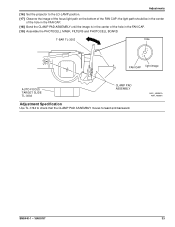
FAN COVER TOOL 11.5 cm (4.5 in.) A091_0024GCA A091_0024GA SM5440-1 - 18NOV97 39 To operate the projector with the LOWER HOUSING removed, make a FAN COVER TOOL. Section 4: Tools Tools TL-1744 TL-2264 TL-3002 TL-3003 TL-3005 TL-3255 TL-4276 Tool Description AUTO-FOCUS GAUGE FOCUS TEST (flat field) AUTO-FOCUS TARGET SLIDE ADJUSTMENT T-BAR ADJUSTMENT TOOL Torx DRIVER SET SUPER LUBE DIGITAL MULTIMETER Tools The LOWER HOUSING ASSEMBLY is a part of the cooling function. Cut here.
FAN COVER TOOL 11.5 cm (4.5 in.) A091_0024GCA A091_0024GA SM5440-1 - 18NOV97 39 To operate the projector with the LOWER HOUSING removed, make a FAN COVER TOOL. Section 4: Tools Tools TL-1744 TL-2264 TL-3002 TL-3003 TL-3005 TL-3255 TL-4276 Tool Description AUTO-FOCUS GAUGE FOCUS TEST (flat field) AUTO-FOCUS TARGET SLIDE ADJUSTMENT T-BAR ADJUSTMENT TOOL Torx DRIVER SET SUPER LUBE DIGITAL MULTIMETER Tools The LOWER HOUSING ASSEMBLY is a part of the cooling function. Cut here.
Service Manual
Page 40
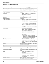
...C power to center ratio is 2.5 mA. 18NOV97 - SERVICE MANUAL Section 5: Specifications Electrical Supply Item Power Consumption Dimensions Slide size Slide change time LAMP and voltages Lumen Output Operating temperature Cooling Approvals Environmental storage Environmental operation Safety Dielectric strength 40 Desription Standard ... 27 C (70 - 80 F), 20 - 60% humidity optimum Fan speed is 2780 or 3000 RPMs, 1360 BTUs per hour to cool projector UL Complies with storage test specifications (TS 172) Complies with European specification DIN 19027 • 4.5 C (40 F), 15% humidity in low...
...C power to center ratio is 2.5 mA. 18NOV97 - SERVICE MANUAL Section 5: Specifications Electrical Supply Item Power Consumption Dimensions Slide size Slide change time LAMP and voltages Lumen Output Operating temperature Cooling Approvals Environmental storage Environmental operation Safety Dielectric strength 40 Desription Standard ... 27 C (70 - 80 F), 20 - 60% humidity optimum Fan speed is 2780 or 3000 RPMs, 1360 BTUs per hour to cool projector UL Complies with storage test specifications (TS 172) Complies with European specification DIN 19027 • 4.5 C (40 F), 15% humidity in low...
Service Manual
Page 41
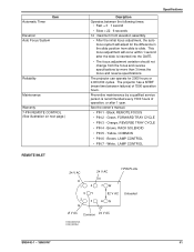
The projector can operate for the difference in the slide position from the focus and reverse specifications by a qualified service person is recommended every 1500 hours of 7500 operation hours. Black, REMOTE FOCUS • PIN 2 - ... • PIN 7 - This focus adjustment will adjust for 2000 hours or 2,000,000 cycles. Green, FORWARD TRAY CYCLE • PIN 3 - Yellow, COMMON • PIN 6 - The projector has a MTBF (mean time between the following times: • Fast = 3 1 second • Slow = 22 6 seconds 14 maximum front elevation assembly. • After the initial focus...
The projector can operate for the difference in the slide position from the focus and reverse specifications by a qualified service person is recommended every 1500 hours of 7500 operation hours. Black, REMOTE FOCUS • PIN 2 - ... • PIN 7 - This focus adjustment will adjust for 2000 hours or 2,000,000 cycles. Green, FORWARD TRAY CYCLE • PIN 3 - Yellow, COMMON • PIN 6 - The projector has a MTBF (mean time between the following times: • Fast = 3 1 second • Slow = 22 6 seconds 14 maximum front elevation assembly. • After the initial focus...

Service Manual
Page 44
... SMALL COMPONENT BOARD ASSEMBLY 256809 Voltages WWK R A V V O B Y B J1 R3 CR2 CR3 CR4 Q1 Q2 R6 R4 R5 C5 R17 C4 R Y G N R WW J2 F1 R7 CR5 SLIDE PROJECTOR BOARD Q3 C1 CR1 R12 ++ R11 R10 C3 C2 R13 R14 CR6 R15 Q4 Description TIMER Circuit TIMER Circuit TIMER Circuit CYCLE HOLD DOWN REVERSE...
... SMALL COMPONENT BOARD ASSEMBLY 256809 Voltages WWK R A V V O B Y B J1 R3 CR2 CR3 CR4 Q1 Q2 R6 R4 R5 C5 R17 C4 R Y G N R WW J2 F1 R7 CR5 SLIDE PROJECTOR BOARD Q3 C1 CR1 R12 ++ R11 R10 C3 C2 R13 R14 CR6 R15 Q4 Description TIMER Circuit TIMER Circuit TIMER Circuit CYCLE HOLD DOWN REVERSE...
Service Manual
Page 46
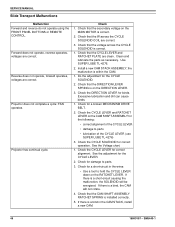
... as necessary. Use SUPER LUBE TL-4276. 2. Check for damage to parts. 3. If there is installed correctly. 5. SERVICE MANUAL Slide Transport Malfunctions Malfunction Forward and reverse do not operate using the FRONT PANEL BUTTONS or REMOTE CONTROL. Reverse does not operate, forward operates,... voltages are correct. Projector does not complete a cycle; Check that the CAM SHAFT ASSEMBLY RATCHET SPRING is a bind, the CAM will be energized. Install a...
... as necessary. Use SUPER LUBE TL-4276. 2. Check for damage to parts. 3. If there is installed correctly. 5. SERVICE MANUAL Slide Transport Malfunctions Malfunction Forward and reverse do not operate using the FRONT PANEL BUTTONS or REMOTE CONTROL. Reverse does not operate, forward operates,... voltages are correct. Projector does not complete a cycle; Check that the CAM SHAFT ASSEMBLY RATCHET SPRING is a bind, the CAM will be energized. Install a...
Service Manual
Page 47
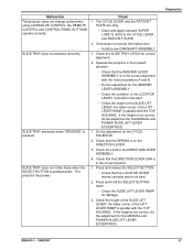
...; Check that the SPRING is pressed down . • Check the SLIDE LIFT LEVER RAMP for a bind in the DIRECTION LEVER ASSEMBLY. 4. Malfunction The projector does not change cycles when using a DISSOLVE CONTROL; SLIDE TRAY does not rotate freely when the SELECT BUTTON is on the DIRECTION...Do the adjustment for the MANUAL and POWER SLIDE LIFT LEVER ECCENTRICS. 1. Diagnostics SM5440-1 - 18NOV97 47 the lower corner of the SLIDE LIFT LEVER; Check for damage. 3. The projector has power. Check the SLIDE TRAY LATCH for the MANUAL and POWER SLIDE LIFT LEVER ECCENTRICS. If the height is ...
...; Check that the SPRING is pressed down . • Check the SLIDE LIFT LEVER RAMP for a bind in the DIRECTION LEVER ASSEMBLY. 4. Malfunction The projector does not change cycles when using a DISSOLVE CONTROL; SLIDE TRAY does not rotate freely when the SELECT BUTTON is on the DIRECTION...Do the adjustment for the MANUAL and POWER SLIDE LIFT LEVER ECCENTRICS. 1. Diagnostics SM5440-1 - 18NOV97 47 the lower corner of the SLIDE LIFT LEVER; Check for damage. 3. The projector has power. Check the SLIDE TRAY LATCH for the MANUAL and POWER SLIDE LIFT LEVER ECCENTRICS. If the height is ...
