Service Manual
Page 2
...information contained herein is based on the experience and knowledge relating to the subject matter gained by this information. This equipment includes parts and assemblies sensitive to damage from any use of Contents Description Page Replacements and Installations 4 Replacing the LOWER HOUSING ASSEMBLY 4 ...Replacing the LENS MOUNT ASSEMBLY - Non Auto Focus Model 20 Installing the LENS MOUNT ASSEMBLY - No patent license is caused by Kodak's negligence or other fault. Auto Focus Models 21 Installing the FOCUS SHAFT ASSEMBLY 23 Replacing the FOCUS SHAFT ASSEMBLY - Table ...
...information contained herein is based on the experience and knowledge relating to the subject matter gained by this information. This equipment includes parts and assemblies sensitive to damage from any use of Contents Description Page Replacements and Installations 4 Replacing the LOWER HOUSING ASSEMBLY 4 ...Replacing the LENS MOUNT ASSEMBLY - Non Auto Focus Model 20 Installing the LENS MOUNT ASSEMBLY - No patent license is caused by Kodak's negligence or other fault. Auto Focus Models 21 Installing the FOCUS SHAFT ASSEMBLY 23 Replacing the FOCUS SHAFT ASSEMBLY - Table ...
Service Manual
Page 3
Auto Focus Models Adjustment Specification 28 Adjusting the NULL 29 Adjusting the PHOTOCELL 30 Adjusting the CLAMP PAD ASSEMBLY 34 Adjusting the DARK SHUTTER 34 Lubrication 36 Tools 39 Specifications 40 Diagnostics 42 MAIN MOTOR Voltages 42 PHOTOCELL Voltages 43 5-PIN REMOTE CORD PLUG Voltages 43 SMALL COMPONENT BOARD ASSEMBLY 256809 Voltages 44 Voltage Specifications - General Parts 45 Power, Illumination, and Cooling Malfunctions 45 Slide Transport Malfunctions 46 Focus Malfunctions 48 SM5440-1 - 18NOV97 3 Adjusting the Focus Light Path -
Auto Focus Models Adjustment Specification 28 Adjusting the NULL 29 Adjusting the PHOTOCELL 30 Adjusting the CLAMP PAD ASSEMBLY 34 Adjusting the DARK SHUTTER 34 Lubrication 36 Tools 39 Specifications 40 Diagnostics 42 MAIN MOTOR Voltages 42 PHOTOCELL Voltages 43 5-PIN REMOTE CORD PLUG Voltages 43 SMALL COMPONENT BOARD ASSEMBLY 256809 Voltages 44 Voltage Specifications - General Parts 45 Power, Illumination, and Cooling Malfunctions 45 Slide Transport Malfunctions 46 Focus Malfunctions 48 SM5440-1 - 18NOV97 3 Adjusting the Focus Light Path -
Service Manual
Page 5
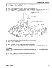
...] Remove the FAN BELT. [18] Remove the 3 Torx SCREWS from the BLOWER COVER ASSEMBLY. [7] Lift the GRILLE ASSEMBLY in . wires are still connected to the parts; WIRE TIE (not shown) KK models BLOWER COVER WIRE TIE GRILLE ASSEMBLY A100_0031HCA A100_0031HA [10] Remove the 2 long Torx SCREWS from the MOTOR. [13] Lift...
...] Remove the FAN BELT. [18] Remove the 3 Torx SCREWS from the BLOWER COVER ASSEMBLY. [7] Lift the GRILLE ASSEMBLY in . wires are still connected to the parts; WIRE TIE (not shown) KK models BLOWER COVER WIRE TIE GRILLE ASSEMBLY A100_0031HCA A100_0031HA [10] Remove the 2 long Torx SCREWS from the MOTOR. [13] Lift...
Service Manual
Page 18
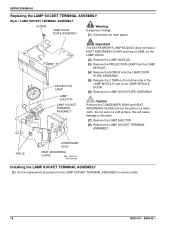
.... [4] Remove the SCREW from the LAMP DOOR PLATE ASSEMBLY. [5] Release the 2 TABS on a clean cloth. Do not set the parts on the bottom side of the LAMP MODULE next to the parts. [7] Remove the LAMP EJECTOR. [8] Remove the LAMP SOCKET TERMINAL ASSEMBLY. TAB (2) CONDENSER LENS HEAT ABSORBING GLASS A091_0018CCA A091_0018CA Installing the...
.... [4] Remove the SCREW from the LAMP DOOR PLATE ASSEMBLY. [5] Release the 2 TABS on a clean cloth. Do not set the parts on the bottom side of the LAMP MODULE next to the parts. [7] Remove the LAMP EJECTOR. [8] Remove the LAMP SOCKET TERMINAL ASSEMBLY. TAB (2) CONDENSER LENS HEAT ABSORBING GLASS A091_0018CCA A091_0018CA Installing the...
Service Manual
Page 36
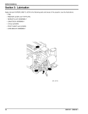
SERVICE MANUAL Section 3: Lubrication Apply lubricant SUPER LUBE TL-4276 to the following parts and areas of the projector; SM5440-1 see the illustrations. • FAN • INDEXER LEVER and TOP PLATE • WORM PULLEY ASSEMBLY • CAM STACK ASSEMBLY • CYCLE LEVERS • PIVOT SHAFT and LEVERS • LENS MOUNT ASSEMBLY A091_4037GA 36 18NOV97 -
SERVICE MANUAL Section 3: Lubrication Apply lubricant SUPER LUBE TL-4276 to the following parts and areas of the projector; SM5440-1 see the illustrations. • FAN • INDEXER LEVER and TOP PLATE • WORM PULLEY ASSEMBLY • CAM STACK ASSEMBLY • CYCLE LEVERS • PIVOT SHAFT and LEVERS • LENS MOUNT ASSEMBLY A091_4037GA 36 18NOV97 -
Service Manual
Page 39
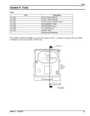
FAN COVER TOOL 11.5 cm (4.5 in.) A091_0024GCA A091_0024GA SM5440-1 - 18NOV97 39 Cut here. To operate the projector with the LOWER HOUSING removed, make a FAN COVER TOOL. Section 4: Tools Tools TL-1744 TL-2264 TL-3002 TL-3003 TL-3005 TL-3255 TL-4276 Tool Description AUTO-FOCUS GAUGE FOCUS TEST (flat field) AUTO-FOCUS TARGET SLIDE ADJUSTMENT T-BAR ADJUSTMENT TOOL Torx DRIVER SET SUPER LUBE DIGITAL MULTIMETER Tools The LOWER HOUSING ASSEMBLY is a part of the cooling function.
FAN COVER TOOL 11.5 cm (4.5 in.) A091_0024GCA A091_0024GA SM5440-1 - 18NOV97 39 Cut here. To operate the projector with the LOWER HOUSING removed, make a FAN COVER TOOL. Section 4: Tools Tools TL-1744 TL-2264 TL-3002 TL-3003 TL-3005 TL-3255 TL-4276 Tool Description AUTO-FOCUS GAUGE FOCUS TEST (flat field) AUTO-FOCUS TARGET SLIDE ADJUSTMENT T-BAR ADJUSTMENT TOOL Torx DRIVER SET SUPER LUBE DIGITAL MULTIMETER Tools The LOWER HOUSING ASSEMBLY is a part of the cooling function.
Service Manual
Page 45
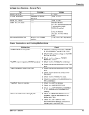
... MECHANISM for damage. 2. Check that the FAN BELT is clean. 4. Check the condition of the BEARING in the FAN area. 1. Voltage Specifications - General Parts Part FOCUS MOTOR CYCLE SOLENOID RACK SOLENOID LAMP RECEPTACLE Procedure -----Press the REVERSE BUTTON DROPPING RESISTOR Move to the LO LAMP position. The LAMP does not...
... MECHANISM for damage. 2. Check that the FAN BELT is clean. 4. Check the condition of the BEARING in the FAN area. 1. Voltage Specifications - General Parts Part FOCUS MOTOR CYCLE SOLENOID RACK SOLENOID LAMP RECEPTACLE Procedure -----Press the REVERSE BUTTON DROPPING RESISTOR Move to the LO LAMP position. The LAMP does not...
Service Manual
Page 46
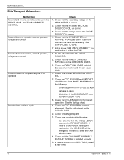
... REMOTE CONTROL. Use SUPER LUBE TL-4276. 2. Check that the secondary voltage on the CAM SHAFT ASSEMBLY for damage to parts • lubrication of the CYCLE LEVER • damage to parts. 3. Check the CYCLE SOLENOID for correct alignment. Check for the following: • correct alignment of the CYCLE LEVER (... for the CYCLE SOLENOID. 2. If there is within the CAM. 1. Check that the DIRECTION LEVER SPRING is correct. 1. Clean and lubricate the parts as necessary. Do the adjustment for binds. Check that the voltage across the CYCLE SOLENOID COIL are clean.
... REMOTE CONTROL. Use SUPER LUBE TL-4276. 2. Check that the secondary voltage on the CAM SHAFT ASSEMBLY for damage to parts • lubrication of the CYCLE LEVER • damage to parts. 3. Check the CYCLE SOLENOID for correct alignment. Check for the following: • correct alignment of the CYCLE LEVER (... for the CYCLE SOLENOID. 2. If there is within the CAM. 1. Check that the DIRECTION LEVER SPRING is correct. 1. Clean and lubricate the parts as necessary. Do the adjustment for binds. Check that the voltage across the CYCLE SOLENOID COIL are clean.
Service Manual
Page 48
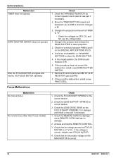
Focus Malfunctions Check 1. Remove R3 and install a new 68K W 1/4 W RESISTOR (part 220040). 2. If the voltage is still a malfunction, install a new PHOTOCELL. Check for changes in W. 3. If this procedure does not correct the malfunction, install a ...the voltage across the FOCUS MOTOR is correct. 48 18NOV97 - Check the REMOTE CORD for damage and install a new part if necessary. 1. Check the LENS SUPPORT SPRING for correct operation and install a new part if necessary. 2. Check the VARIABLE RESISTOR for correct tension. 3. Check that has no damage. 2. Check the ...
Focus Malfunctions Check 1. Remove R3 and install a new 68K W 1/4 W RESISTOR (part 220040). 2. If the voltage is still a malfunction, install a new PHOTOCELL. Check for changes in W. 3. If this procedure does not correct the malfunction, install a ...the voltage across the FOCUS MOTOR is correct. 48 18NOV97 - Check the REMOTE CORD for damage and install a new part if necessary. 1. Check the LENS SUPPORT SPRING for correct operation and install a new part if necessary. 2. Check the VARIABLE RESISTOR for correct tension. 3. Check that has no damage. 2. Check the ...