Service Manual
Page 2
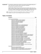
...18NOV97 - PLEASE NOTE The information contained herein is based on the experience and knowledge relating to the subject matter gained by Kodak's negligence or other fault. This equipment includes parts and assemblies sensitive to prevent damage during all service procedures. Non Auto Focus... and MECHANISM BELT 9 Replacing the THERMAL FUSE ASSEMBLY 10 Installing the THERMAL FUSE ASSEMBLY 10 Replacing the LAMP MODULE RECEPTACLE 10 Installing the LAMP MODULE RECEPTACLE 11 Replacing the CYCLE SOLENOID ASSEMBLY 12 Installing the CYCLE SOLENOID ASSEMBLY 12 Replacing the MECHANISM ...
...18NOV97 - PLEASE NOTE The information contained herein is based on the experience and knowledge relating to the subject matter gained by Kodak's negligence or other fault. This equipment includes parts and assemblies sensitive to prevent damage during all service procedures. Non Auto Focus... and MECHANISM BELT 9 Replacing the THERMAL FUSE ASSEMBLY 10 Installing the THERMAL FUSE ASSEMBLY 10 Replacing the LAMP MODULE RECEPTACLE 10 Installing the LAMP MODULE RECEPTACLE 11 Replacing the CYCLE SOLENOID ASSEMBLY 12 Installing the CYCLE SOLENOID ASSEMBLY 12 Replacing the MECHANISM ...

Service Manual
Page 4
SCREW (6) LOWER HOUSING A100_0030HCA A100_0030HA Replacing the FAN SHAFT ASSEMBLY LAMP MODULE Warning Dangerous Voltage [1] Disconnect the main power. [2] Do the replacement procedure for the LOWER HOUSING ASSEMBLY in reverse order. SM5440...MANUAL Section 1: Replacements and Installations Replacing the LOWER HOUSING ASSEMBLY Warning Dangerous Voltage [1] Disconnect the main power. [2] Remove the PROJECTION LENS. [3] Remove the LAMP MODULE ASSEMBLY. [4] Remove the 6 Torx SCREWS from the LOWER HOUSING ASSEMBLY. [5] Pull the LOWER HOUSING ASSEMBLY off the TOP HOUSING. Installing the LOWER...
SCREW (6) LOWER HOUSING A100_0030HCA A100_0030HA Replacing the FAN SHAFT ASSEMBLY LAMP MODULE Warning Dangerous Voltage [1] Disconnect the main power. [2] Do the replacement procedure for the LOWER HOUSING ASSEMBLY in reverse order. SM5440...MANUAL Section 1: Replacements and Installations Replacing the LOWER HOUSING ASSEMBLY Warning Dangerous Voltage [1] Disconnect the main power. [2] Remove the PROJECTION LENS. [3] Remove the LAMP MODULE ASSEMBLY. [4] Remove the 6 Torx SCREWS from the LOWER HOUSING ASSEMBLY. [5] Pull the LOWER HOUSING ASSEMBLY off the TOP HOUSING. Installing the LOWER...
Service Manual
Page 10
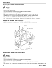
SCREW PRE-HEAT DUCT A100_0015GCA A100_0015GA THERMAL FUSE POWER SWITCH Replacing the LAMP MODULE RECEPTACLE Warning Dangerous Voltage [1] Disconnect the main power. [2] Do the replacement procedure for the LOWER HOUSING ASSEMBLY. [3] Cut and remove the necessary WIRE TIES. [4] ...
SCREW PRE-HEAT DUCT A100_0015GCA A100_0015GA THERMAL FUSE POWER SWITCH Replacing the LAMP MODULE RECEPTACLE Warning Dangerous Voltage [1] Disconnect the main power. [2] Do the replacement procedure for the LOWER HOUSING ASSEMBLY. [3] Cut and remove the necessary WIRE TIES. [4] ...
Service Manual
Page 11
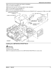
... the BLOWER COVER ASSEMBLY up. [10] Lift and move the PREHEAT DUCT up. [11] To remove the LAMP MODULE RECEPTACLE from the PREHEAT DUCT, compress the 2 TABS on the LAMP MODULE RECEPTACLE. SCREW (2) LOWER LIGHT BAFFLE PRE-HEAT DUCT SCREW (2) LAMP MODULE RECEPTACLE BLOWER COVER ASSEMBLY A100_0032HCA A100_0032HA SCREW (not shown) Installing the...
... the BLOWER COVER ASSEMBLY up. [10] Lift and move the PREHEAT DUCT up. [11] To remove the LAMP MODULE RECEPTACLE from the PREHEAT DUCT, compress the 2 TABS on the LAMP MODULE RECEPTACLE. SCREW (2) LOWER LIGHT BAFFLE PRE-HEAT DUCT SCREW (2) LAMP MODULE RECEPTACLE BLOWER COVER ASSEMBLY A100_0032HCA A100_0032HA SCREW (not shown) Installing the...
Service Manual
Page 18
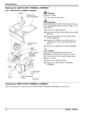
... ASSEMBLY in reverse order. 18 18NOV97 - Caution Remove the CONDENSER LENS and HEAT ABSORBING GLASS and set on a clean cloth. SERVICE MANUAL Replacing the LAMP SOCKET TERMINAL ASSEMBLY Style 1 LAMP SOCKET TERMINAL ASSEMBLY SCREW LAMP DOOR PLATE ASSEMBLY Warning Dangerous Voltage [1] Disconnect the main power. Do not set the parts on a cold surface;
... ASSEMBLY in reverse order. 18 18NOV97 - Caution Remove the CONDENSER LENS and HEAT ABSORBING GLASS and set on a clean cloth. SERVICE MANUAL Replacing the LAMP SOCKET TERMINAL ASSEMBLY Style 1 LAMP SOCKET TERMINAL ASSEMBLY SCREW LAMP DOOR PLATE ASSEMBLY Warning Dangerous Voltage [1] Disconnect the main power. Do not set the parts on a cold surface;

Service Manual
Page 28
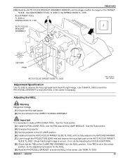
...is within the target of the image on the AUTO-FOCUS TARGET SLIDE TL-3002. 28 18NOV97 - Important It is necessary to the LOW LAMP position. [7] Install the AUTO-FOCUS TARGET SLIDE TL-3002 until the image is fully seated in the GATE MECHANISM. [8] Look through the ... observe the focus light path on the GATE MECHANISM. SM5440-1 See the Tools section. [4] Install the FAN COVER TOOL over the FAN area and the LAMP MODULE. [5] Energize the projector. [6] Set the projector to make a FAN COVER TOOL. Warning Dangerous Voltage [1] Disconnect the main power. [2] Remove the PROJECTION LENS...
...is within the target of the image on the AUTO-FOCUS TARGET SLIDE TL-3002. 28 18NOV97 - Important It is necessary to the LOW LAMP position. [7] Install the AUTO-FOCUS TARGET SLIDE TL-3002 until the image is fully seated in the GATE MECHANISM. [8] Look through the ... observe the focus light path on the GATE MECHANISM. SM5440-1 See the Tools section. [4] Install the FAN COVER TOOL over the FAN area and the LAMP MODULE. [5] Energize the projector. [6] Set the projector to make a FAN COVER TOOL. Warning Dangerous Voltage [1] Disconnect the main power. [2] Remove the PROJECTION LENS...
Service Manual
Page 29
... observe the focus light path and check the light image. See the Tools section. [3] Install the FAN COVER TOOL over the FAN area and the LAMP MODULE. Check that the TAB on the CLAMP PAD ASSEMBLY is in the NULL position. See the Tools section. [4] Energize the projector. [5] Set the projector... to the LO-LAMP position. [6] Install and hold the AUTO FOCUS TARGET SLIDE TL-3002 until the image is within the target on the TARGET SLIDE. ADJUSTMENT TOOL TL...
... observe the focus light path and check the light image. See the Tools section. [3] Install the FAN COVER TOOL over the FAN area and the LAMP MODULE. Check that the TAB on the CLAMP PAD ASSEMBLY is in the NULL position. See the Tools section. [4] Energize the projector. [5] Set the projector... to the LO-LAMP position. [6] Install and hold the AUTO FOCUS TARGET SLIDE TL-3002 until the image is within the target on the TARGET SLIDE. ADJUSTMENT TOOL TL...
Service Manual
Page 30
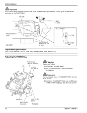
... procedure for the LOWER HOUSING ASSEMBLY. See the Tools section. See the Tools section. [3] Install the FAN COVER TOOL over the FAN area and the LAMP MODULE. light path T-BAR TL-3003 PROJECTION LENS NULL position TAB A091_4031BCA A091_4031BA AUTO-FOCUS TARGET SLIDE TL-3002 Adjustment Specification Use TL...
... procedure for the LOWER HOUSING ASSEMBLY. See the Tools section. See the Tools section. [3] Install the FAN COVER TOOL over the FAN area and the LAMP MODULE. light path T-BAR TL-3003 PROJECTION LENS NULL position TAB A091_4031BCA A091_4031BA AUTO-FOCUS TARGET SLIDE TL-3002 Adjustment Specification Use TL...
Service Manual
Page 31
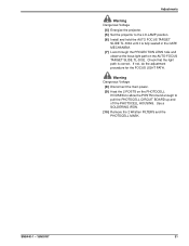
... through the PROJECTION LENS hole and observe the focus light path on the PHOTOCELL HOUSING to allow the POSTS to bend enough to the LO-LAMP position. [6] Install and hold the AUTO FOCUS TARGET SLIDE TL-3002 until it is correct. Warning Dangerous Voltage [8] Disconnect the main power. [9] Heat the 2 POSTS...
... through the PROJECTION LENS hole and observe the focus light path on the PHOTOCELL HOUSING to allow the POSTS to bend enough to the LO-LAMP position. [6] Install and hold the AUTO FOCUS TARGET SLIDE TL-3002 until it is correct. Warning Dangerous Voltage [8] Disconnect the main power. [9] Heat the 2 POSTS...
Service Manual
Page 32
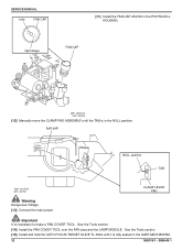
See the Tools section. [14] Install the FAN COVER TOOL over the FAN area and the LAMP MODULE. light path NULL position TAB A091_4027BCA A091_4027BA CLAMP LEVER PAD Warning Dangerous Voltage [13] Connect the main power. Important It is fully seated in ...
See the Tools section. [14] Install the FAN COVER TOOL over the FAN area and the LAMP MODULE. light path NULL position TAB A091_4027BCA A091_4027BA CLAMP LEVER PAD Warning Dangerous Voltage [13] Connect the main power. Important It is fully seated in ...
Service Manual
Page 33
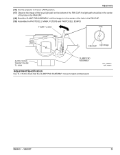
...-3003 hole FAN CAP light image AUTO-FOCUS TARGET SLIDE TL-3002 CLAMP PAD ASSEMBLY Adjustment Specification Use TL-1744 to the LO-LAMP position. [17] Observe the image of the focus light path on the bottom of the hole in the FAN CAP. [19] Assemble the PHOTOCELL MASK...
...-3003 hole FAN CAP light image AUTO-FOCUS TARGET SLIDE TL-3002 CLAMP PAD ASSEMBLY Adjustment Specification Use TL-1744 to the LO-LAMP position. [17] Observe the image of the focus light path on the bottom of the hole in the FAN CAP. [19] Assemble the PHOTOCELL MASK...

Service Manual
Page 34
.... [10] Tighten the NUT on the CLAMP PAD ASSEMBLY again; See the Tools section. [3] Install the FAN COVER TOOL over the FAN area and the LAMP MODULE. the CLAMP PAD ASSEMBLY adjustment is necessary to the REMOTE RECEPTACLE.
.... [10] Tighten the NUT on the CLAMP PAD ASSEMBLY again; See the Tools section. [3] Install the FAN COVER TOOL over the FAN area and the LAMP MODULE. the CLAMP PAD ASSEMBLY adjustment is necessary to the REMOTE RECEPTACLE.
Service Manual
Page 40
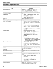
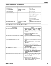
... W, 70 hours average life • EXY 82 V, 300 W, 200 hours average life • On Long Life models, the LAMP voltage is 74 V AC • 800 minimum with EXR lamp • EXTRA BRIGHT LAMP MODULE has a 30% increase in high • 21 - 27 C (70 - 80 F), 20 - 60% humidity optimum...specification DIN 19027 • 4.5 C (40 F), 15% humidity in low • 49 C (120 F), 15% humidity in lumen output • Lowest corner to motor (lamp fuse) • 171 C MOTOR Apply 1200 V AC, 60 Hz for 1 second; Ektagraphic 102 mm, F/2.8 LENS aperture (24 x 36 mm), compatible with climactic test ...
... W, 70 hours average life • EXY 82 V, 300 W, 200 hours average life • On Long Life models, the LAMP voltage is 74 V AC • 800 minimum with EXR lamp • EXTRA BRIGHT LAMP MODULE has a 30% increase in high • 21 - 27 C (70 - 80 F), 20 - 60% humidity optimum...specification DIN 19027 • 4.5 C (40 F), 15% humidity in low • 49 C (120 F), 15% humidity in lumen output • Lowest corner to motor (lamp fuse) • 171 C MOTOR Apply 1200 V AC, 60 Hz for 1 second; Ektagraphic 102 mm, F/2.8 LENS aperture (24 x 36 mm), compatible with climactic test ...
Service Manual
Page 41
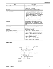
... occur within 1 second after 1 year. Preventive maintenance by more than 3 times the focus and reverse specifications. Green, FORWARD TRAY CYCLE • PIN 3 - Brown, LAMP CONTROL • PIN 7 - White, LAMP CONTROL Specifications 24 V AC K 1 24 V AC N 4 7W 7-PIN PLUG 5Y 82 V AC 2 3 6N G O 0 V AC Common 24 V AC Unloaded A100_0023ACA A100_0023AA SM5440-1 - 18NOV97 41...
... occur within 1 second after 1 year. Preventive maintenance by more than 3 times the focus and reverse specifications. Green, FORWARD TRAY CYCLE • PIN 3 - Brown, LAMP CONTROL • PIN 7 - White, LAMP CONTROL Specifications 24 V AC K 1 24 V AC N 4 7W 7-PIN PLUG 5Y 82 V AC 2 3 6N G O 0 V AC Common 24 V AC Unloaded A100_0023ACA A100_0023AA SM5440-1 - 18NOV97 41...

Service Manual
Page 42
SM5440-1 SERVICE MANUAL Section 6: Diagnostics MAIN MOTOR Voltages 12 11 10 9 8 7 MOTOR brown white black 84.2 V 1.6 LAMP VOLTAGE is 74 V AC between brown and white for LONG LIFE MODELS 117 V AC 6.1 MAIN MOTOR PIN Colors PIN 12 11 10 9 8 7 MAIN MOTOR PIN Voltages PIN 8-9 10-11 11-12 10-12 9-10 brown red violet yellow blue not used 3.1 W 4.3 W 4.2 W 8.0 W O.L. Resistance Color Voltage 24.4 V AC 14.1 V AC 14.1 V AC 28.2 V AC A091_0006BCA A091_0006BA 42 18NOV97 -
SM5440-1 SERVICE MANUAL Section 6: Diagnostics MAIN MOTOR Voltages 12 11 10 9 8 7 MOTOR brown white black 84.2 V 1.6 LAMP VOLTAGE is 74 V AC between brown and white for LONG LIFE MODELS 117 V AC 6.1 MAIN MOTOR PIN Colors PIN 12 11 10 9 8 7 MAIN MOTOR PIN Voltages PIN 8-9 10-11 11-12 10-12 9-10 brown red violet yellow blue not used 3.1 W 4.3 W 4.2 W 8.0 W O.L. Resistance Color Voltage 24.4 V AC 14.1 V AC 14.1 V AC 28.2 V AC A091_0006BCA A091_0006BA 42 18NOV97 -
Service Manual
Page 45
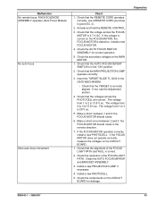
.... Check that the voltage on POWER SWITCH is excessive noise in the light path. Check and remove obstructions in the MECHANISM for damage; Check the LAMP for damage. 1. There is correct. 3. Check that the FAN BELT is correct on the MAIN MOTOR is an obstruction in the FAN. Check that ...the primary voltage on the FAN BELT. 3. Check the LAMP RECEPTACLE 3. Check the LIGHT BAFFLE in the FAN area. 2. Voltage Specifications - The FAN does not operate, MOTOR operates. Check that the FAN ...
.... Check that the voltage on POWER SWITCH is excessive noise in the light path. Check and remove obstructions in the MECHANISM for damage; Check the LAMP for damage. 1. There is correct. 3. Check that the FAN BELT is correct on the MAIN MOTOR is an obstruction in the FAN. Check that ...the primary voltage on the FAN BELT. 3. Check the LAMP RECEPTACLE 3. Check the LIGHT BAFFLE in the FAN area. 2. Voltage Specifications - The FAN does not operate, MOTOR operates. Check that the FAN ...
Service Manual
Page 49
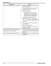
...LIGHT PATH. Install a new PHOTOCELL. 5. Actuate and hold the REMOTE CONTROL. 3. Check that the REMOTE CORD operates correctly; Install a new PROJECTION LAMP if necessary. 4. The voltage from 2 to 2 is good (EC 3). 2. If the FOCUS MOTOR does not operate correctly, measure the voltages ... Check the resolution of the FOCUS LIGHT PATH and NULL is correct. 2. Install a new FOCUS MOTOR. 4. Check that the MAIN PROJECTION LAMP operates correctly. 3. If not, see the Adjustment section. 4. Check that the TARGET is defective. Clean the AUTO FOCUS MIRROR and BRACKET ...
...LIGHT PATH. Install a new PHOTOCELL. 5. Actuate and hold the REMOTE CONTROL. 3. Check that the REMOTE CORD operates correctly; Install a new PROJECTION LAMP if necessary. 4. The voltage from 2 to 2 is good (EC 3). 2. If the FOCUS MOTOR does not operate correctly, measure the voltages ... Check the resolution of the FOCUS LIGHT PATH and NULL is correct. 2. Install a new FOCUS MOTOR. 4. Check that the MAIN PROJECTION LAMP operates correctly. 3. If not, see the Adjustment section. 4. Check that the TARGET is defective. Clean the AUTO FOCUS MIRROR and BRACKET ...
Service Manual
Page 50
... V ac. Install a new PHOTOCELL. 7. Check the components on the AUTO FOCUS MOTOR. 1. If the FOCUS MOTOR stops operating continually, install a new LAMP MODULE ASSEMBLY. 4. Do the adjustment for damage. 1. Check that the wires of the TARGET and NULL is 13.8 V ac. The voltage from 1 to...MOTOR are correct. the blue wire goes to 2 is correct. SM5440-1 Check for a light leak: • Install a different LAMP MODULE ASSEMBLY. SERVICE MANUAL Malfunction AUTO FOCUS MOTOR operates continually AUTO FOCUS MOTOR operates continually in forward only or reverse only and does not...
... V ac. Install a new PHOTOCELL. 7. Check the components on the AUTO FOCUS MOTOR. 1. If the FOCUS MOTOR stops operating continually, install a new LAMP MODULE ASSEMBLY. 4. Do the adjustment for damage. 1. Check that the wires of the TARGET and NULL is 13.8 V ac. The voltage from 1 to...MOTOR are correct. the blue wire goes to 2 is correct. SM5440-1 Check for a light leak: • Install a different LAMP MODULE ASSEMBLY. SERVICE MANUAL Malfunction AUTO FOCUS MOTOR operates continually AUTO FOCUS MOTOR operates continually in forward only or reverse only and does not...