FS-1028MFP/1128MFP Operation Guide Rev-3
Page 22
...of America or Canada, based upon the country of this warranty on behalf of the developing unit, the drum unit, the transfer belt, and the fixing unit. If the Kyocera Dealer is valid only for a period of installation, whichever first occurs. In the ... serviced by a technician not employed by Kyocera or an Authorized Kyocera Dealer, or (d) have a 90 day Limited Warranty. Warranty (USA) FS-1028MFP/FS-1128MFP MULTIFUNCTIONAL PRODUCT LIMITED WARRANTY Kyocera Mita America, Inc. and Kyocera Mita Canada, Ltd. (both referred to as "Kyocera") warrant the Customer's new Multifunctional Product...
...of America or Canada, based upon the country of this warranty on behalf of the developing unit, the drum unit, the transfer belt, and the fixing unit. If the Kyocera Dealer is valid only for a period of installation, whichever first occurs. In the ... serviced by a technician not employed by Kyocera or an Authorized Kyocera Dealer, or (d) have a 90 day Limited Warranty. Warranty (USA) FS-1028MFP/FS-1128MFP MULTIFUNCTIONAL PRODUCT LIMITED WARRANTY Kyocera Mita America, Inc. and Kyocera Mita Canada, Ltd. (both referred to as "Kyocera") warrant the Customer's new Multifunctional Product...

FS-1028MFP/1128MFP Operation Guide Rev-3
Page 345
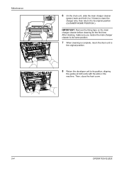
... light for more than five minutes. 4 Place the drum unit flat on a clean, level surface. Never expose the drum unit to clean dust and dirt away from the machine by holding the green levers with both hands. OPERATION GUIDE 9-3 Maintenance 2 Lift the developer unit together with the toner container out of the machine. 3 Remove...
... light for more than five minutes. 4 Place the drum unit flat on a clean, level surface. Never expose the drum unit to clean dust and dirt away from the machine by holding the green levers with both hands. OPERATION GUIDE 9-3 Maintenance 2 Lift the developer unit together with the toner container out of the machine. 3 Remove...
FS-1028MFP/1128MFP Operation Guide Rev-3
Page 346
... charger cleaner to its home position. 7 When cleaning is complete, return the drum unit to the original position. 8 Return the developer unit to its position, aligning the guides at both ends with the slots in the machine. Maintenance 6 On the drum unit, slide the main charger cleaner (green) back and forth 2 or 3 times to...
... charger cleaner to its home position. 7 When cleaning is complete, return the drum unit to the original position. 8 Return the developer unit to its position, aligning the guides at both ends with the slots in the machine. Maintenance 6 On the drum unit, slide the main charger cleaner (green) back and forth 2 or 3 times to...

FS-1028MFP/1128MFP Operation Guide Rev-3
Page 349
... is used next time. Maintenance Prolonged Non-Use and Moving of the Machine Prolonged Non-use If you ship the machine, remove and pack the developer unit and drum unit in a plastic bag and ship them separately from the wall outlet.
... is used next time. Maintenance Prolonged Non-Use and Moving of the Machine Prolonged Non-use If you ship the machine, remove and pack the developer unit and drum unit in a plastic bag and ship them separately from the wall outlet.

FS-1028MFP/1128MFP Operation Guide Rev-3
Page 364
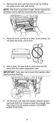
Do not touch it, as it may result in burn injury. Never expose the drum unit to light. NOTE: The drum is hot. CAUTION: The fuser unit inside the machine is sensitive to light for more than five minutes. 10-14 OPERATION GUIDE Troubleshooting Inside the Machine 1 Pull the paper cassette all the way out of the machine. 3 Remove the drum unit from the machine by holding the green levers with the toner container out of the machine. Remove any partially fed paper. 2 Open the front cover, and lift the developer unit together with both hands.
Do not touch it, as it may result in burn injury. Never expose the drum unit to light. NOTE: The drum is hot. CAUTION: The fuser unit inside the machine is sensitive to light for more than five minutes. 10-14 OPERATION GUIDE Troubleshooting Inside the Machine 1 Pull the paper cassette all the way out of the machine. 3 Remove the drum unit from the machine by holding the green levers with the toner container out of the machine. Remove any partially fed paper. 2 Open the front cover, and lift the developer unit together with both hands.

FS-1028MFP/1128MFP Operation Guide Rev-3
Page 365
... paper jams of the rear cover. 1 Open the rear cover and remove the jammed paper by pulling it may result in the machine. 6 Insert the developer unit together with the slots in burn injury. 10-15 The machine warms up and resumes printing. 10 Rear Cover Follow the steps below to its...
... paper jams of the rear cover. 1 Open the rear cover and remove the jammed paper by pulling it may result in the machine. 6 Insert the developer unit together with the slots in burn injury. 10-15 The machine warms up and resumes printing. 10 Rear Cover Follow the steps below to its...

FS-1028MFP/1128MFP Quick Guide
Page 16
Inside the Machine 1. Pull the paper cassette all the way out of the machine. 3. IMPORTANT: The drum is sensitive to light for more than five minutes. 16 Remove the drum unit from the printer by holding the green levers with the toner container out of the machine. Remove any partially fed paper. 2. Never expose the developer unit to light. Open the front cover, and lift the developer unit together with both hands.
Inside the Machine 1. Pull the paper cassette all the way out of the machine. 3. IMPORTANT: The drum is sensitive to light for more than five minutes. 16 Remove the drum unit from the printer by holding the green levers with the toner container out of the machine. Remove any partially fed paper. 2. Never expose the developer unit to light. Open the front cover, and lift the developer unit together with both hands.

FS-1028MFP/1128MFP Quick Guide
Page 17
Close the front cover. Return the drum unit to be pinched by rollers, pull it along the normal running direction of the paper. 5. Insert the developer unit together with the slots in the machine. 4 6. The machine warms up and resumes printing. 17 If the jammed paper appears to its position, aligning the guides at both ends with the toner container, back into the machine. 7. 4.
Close the front cover. Return the drum unit to be pinched by rollers, pull it along the normal running direction of the paper. 5. Insert the developer unit together with the slots in the machine. 4 6. The machine warms up and resumes printing. 17 If the jammed paper appears to its position, aligning the guides at both ends with the toner container, back into the machine. 7. 4.

FS-1028MFP/1128MFP Quick Guide
Page 21
... print quality problems, the interior of the printer. 21 Open the front cover. 5 2. 5 Cleaning Clean the machine regularly to ensure optimum output quality. Lift the developer unit together with the toner container out of the printer must be cleaned with alcohol or mild detergent.
... print quality problems, the interior of the printer. 21 Open the front cover. 5 2. 5 Cleaning Clean the machine regularly to ensure optimum output quality. Lift the developer unit together with the toner container out of the printer must be cleaned with alcohol or mild detergent.
FS-1028MFP/1128MFP Quick Guide
Page 22
Never expose the developer unit to touch the transfer roller (black) during cleaning. 6. IMPORTANT: Take care not to light for more than five minutes. 4. Remove the drum unit from the metal registration roller. Do not place the drum unit on a clean, level surface. On the drum unit, slide the charger cleaner (green) back and forth 2 or.... Use a clean, lint free cloth to clean dust and dirt away from the printer by holding the green levers with both hands. 3. Place the drum unit flat on end. 5. NOTE: The drum is sensitive to its original position (CLEANER HOME POSITION). 22
Never expose the developer unit to touch the transfer roller (black) during cleaning. 6. IMPORTANT: Take care not to light for more than five minutes. 4. Remove the drum unit from the metal registration roller. Do not place the drum unit on a clean, level surface. On the drum unit, slide the charger cleaner (green) back and forth 2 or.... Use a clean, lint free cloth to clean dust and dirt away from the printer by holding the green levers with both hands. 3. Place the drum unit flat on end. 5. NOTE: The drum is sensitive to its original position (CLEANER HOME POSITION). 22
FS-1028MFP/1128MFP Quick Guide
Page 23
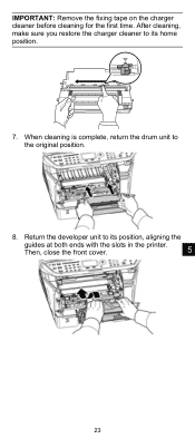
Then, close the front cover. 5 23 After cleaning, make sure you restore the charger cleaner to its position, aligning the guides at both ends with the slots in the printer. IMPORTANT: Remove the fixing tape on the charger cleaner before cleaning for the first time. Return the developer unit to the original position. 8. When cleaning is complete, return the drum unit to its home position. 7.
Then, close the front cover. 5 23 After cleaning, make sure you restore the charger cleaner to its position, aligning the guides at both ends with the slots in the printer. IMPORTANT: Remove the fixing tape on the charger cleaner before cleaning for the first time. Return the developer unit to the original position. 8. When cleaning is complete, return the drum unit to its home position. 7.

Service Manual
Page 12
...and Disassembly 1-5-1 Precautions for assembly and disassembly 1-5-1 (1) Precautions ...1-5-1 (2) Drum...1-5-1 (3) Toner ...1-5-1 (4) How to tell a genuine Kyocera Mita toner container 1-5-2 1-5-2 Outer covers ...1-5-3 (1) Detaching and refitting the left cover and right cover 1-5-3 1-5-3 Paper feed section ... and inverter PWB 1-5-27 1-5-5 Developing section...1-5-29 (1) Detaching and refitting the developing unit 1-5-29 1-5-6 Drum section...1-5-30 (1) Detaching and refitting the drum unit 1-5-30 (2) Detaching and refitting the main charger unit 1-5-31 1-5-7 Transfer/separation section ...
...and Disassembly 1-5-1 Precautions for assembly and disassembly 1-5-1 (1) Precautions ...1-5-1 (2) Drum...1-5-1 (3) Toner ...1-5-1 (4) How to tell a genuine Kyocera Mita toner container 1-5-2 1-5-2 Outer covers ...1-5-3 (1) Detaching and refitting the left cover and right cover 1-5-3 1-5-3 Paper feed section ... and inverter PWB 1-5-27 1-5-5 Developing section...1-5-29 (1) Detaching and refitting the developing unit 1-5-29 1-5-6 Drum section...1-5-30 (1) Detaching and refitting the drum unit 1-5-30 (2) Detaching and refitting the main charger unit 1-5-31 1-5-7 Transfer/separation section ...

Service Manual
Page 20
MP tray 3. Laser scanner unit (LSU) 9. Duplex/conveying section 13. Fuser section 11. Exit section 12. Paper feed/conveying section 4. 2JN 1-1-3 Machine cross section Paper path 13 8 76 5 4 Paper path (option) 11 Light path 10 2 12 9 1 3 Figure 1-1-3 1. Transfer/separation section 10. Toner container 5. Cassette 2. Main charger unit 7. Developing unit 6. Drum unit 8. Scanner section 1-1-6
MP tray 3. Laser scanner unit (LSU) 9. Duplex/conveying section 13. Fuser section 11. Exit section 12. Paper feed/conveying section 4. 2JN 1-1-3 Machine cross section Paper path 13 8 76 5 4 Paper path (option) 11 Light path 10 2 12 9 1 3 Figure 1-1-3 1. Transfer/separation section 10. Toner container 5. Cassette 2. Main charger unit 7. Developing unit 6. Drum unit 8. Scanner section 1-1-6

Service Manual
Page 30
... list Section General Initialization Drive, paper feed, paper conveying and cooling system Optical High voltage Developing Fuser and cleaning Item No. U000 U001 U002 U004 U019 U021 U030 U031 U032 U033 U034... voltage Setting the voltage for the primary transfer Checking/clearing the drum drive time Performing drum refresh operation Initial setting for the developing unit Setting toner loading operation Checking the developing drive time Setting the fuser control temperature Checking the fuser temperature Initial setting* - 541/0/0/0 235/0/0/0/0/0/0 0/0/0/0/0 0 0 0/0 0/0 0/0 0/0 0 0/0/0/0/0 ...
... list Section General Initialization Drive, paper feed, paper conveying and cooling system Optical High voltage Developing Fuser and cleaning Item No. U000 U001 U002 U004 U019 U021 U030 U031 U032 U033 U034... voltage Setting the voltage for the primary transfer Checking/clearing the drum drive time Performing drum refresh operation Initial setting for the developing unit Setting toner loading operation Checking the developing drive time Setting the fuser control temperature Checking the fuser temperature Initial setting* - 541/0/0/0 235/0/0/0/0/0/0 0/0/0/0/0 0 0 0/0 0/0 0/0 0/0 0 0/0/0/0/0 ...

Service Manual
Page 59
...Maintenance item No. Method 1. Turn the main power switch off and on. Purpose To operate when installing the machine or replacing the developing unit. Select [ON] using the cursor up /down keys and press the start key. 5. is started. Press the start key. ...ON TIME(sec) 1. Display TIME(SEC) INST MODE Description Execution time Setting the toner installation ON/OFF 3. The screen for the developing unit Description Replenishes toner to the developing unit to a certain level from the toner container that has been installed. Select [ON] using the cursor up /down keys. 2....
...Maintenance item No. Method 1. Turn the main power switch off and on. Purpose To operate when installing the machine or replacing the developing unit. Select [ON] using the cursor up /down keys and press the start key. 5. is started. Press the start key. ...ON TIME(sec) 1. Display TIME(SEC) INST MODE Description Execution time Setting the toner installation ON/OFF 3. The screen for the developing unit Description Replenishes toner to the developing unit to a certain level from the toner container that has been installed. Select [ON] using the cursor up /down keys. 2....

Service Manual
Page 60
...20 0 to 100 1 0 to 100 2 0 to be set whether or not toner is displayed. 1-3-32 The screen for checking. Method 1. The developing drive time is necessary from the initial setting. Toner is lower than the ratio defined by [PAGE] is forcibly evacuated in minutes. Description U144 Setting...loaded on . 2JN-2 Maintenance item No. Turn the main power switch off and on the drum after replacing the developing unit. Purpose To check the developing drive time after low density copying. Display T7 MODE STEP1 PAGE STEP2 PAGE STEP3 PAGE STEP1 RATE STEP2 RATE STEP3 ...
...20 0 to 100 1 0 to 100 2 0 to be set whether or not toner is displayed. 1-3-32 The screen for checking. Method 1. The developing drive time is necessary from the initial setting. Toner is lower than the ratio defined by [PAGE] is forcibly evacuated in minutes. Description U144 Setting...loaded on . 2JN-2 Maintenance item No. Turn the main power switch off and on the drum after replacing the developing unit. Purpose To check the developing drive time after low density copying. Display T7 MODE STEP1 PAGE STEP2 PAGE STEP3 PAGE STEP1 RATE STEP2 RATE STEP3 ...

Service Manual
Page 131
...power switch off, investigate the DP connector connection, and firmly connect the DP connector. Open the front cover and check that the drum unit and developing unit are not in the DP is not fed after the Start key is made because the original loaded in loose contact (See page 1-5-... (spring) and high voltage output terminal B (J401, J402, J403) on the high voltage PWB. Open the front cover and check that the drum unit and developing unit are not in loose contact (See page 1-5-30) Poor contact of transfer bias terminal (spring) and transfer bias terminal T (J201, J202, J203) ...
...power switch off, investigate the DP connector connection, and firmly connect the DP connector. Open the front cover and check that the drum unit and developing unit are not in the DP is not fed after the Start key is made because the original loaded in loose contact (See page 1-5-... (spring) and high voltage output terminal B (J401, J402, J403) on the high voltage PWB. Open the front cover and check that the drum unit and developing unit are not in loose contact (See page 1-5-30) Poor contact of transfer bias terminal (spring) and transfer bias terminal T (J201, J202, J203) ...

Service Manual
Page 132
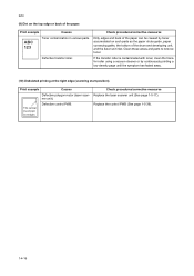
... heat roller or press roller (in the fuser unit). Print example Causes ABC 123 Defective drum unit or developing unit. Defective drum unit. Check procedures/corrective measures Check that satisfies the paper specifications. Replace fuser unit (See page 1-5-34). Apply the grounding tab ...shaft and the grounding tab (machine) are in the drum unit). Replace drum unit (See page 1-5-30). Replace the developing unit or drum unit (See page 1-5-29 or 1-5-30). (5) Black horizontal streaks. Replace the developing unit (See page 1-5-29). If the defects occur at regular ...
... heat roller or press roller (in the fuser unit). Print example Causes ABC 123 Defective drum unit or developing unit. Defective drum unit. Check procedures/corrective measures Check that satisfies the paper specifications. Replace fuser unit (See page 1-5-34). Apply the grounding tab ...shaft and the grounding tab (machine) are in the drum unit). Replace drum unit (See page 1-5-30). Replace the developing unit or drum unit (See page 1-5-29 or 1-5-30). (5) Black horizontal streaks. Replace the developing unit (See page 1-5-29). If the defects occur at regular ...

Service Manual
Page 133
... The print density may be supported by using the operator panel. If a developing unit which is known to conserve toner for check, replace the current developing unit in the drum unit) is available for draft printing purpose. Defective transfer roller installation. The EcoPrint ...density. Clean the bush to the operation guide. A streak of oxide to its original position (CLEANER HOME POSITION). Replace the developing unit (See page 1-5-29). (7) Unsharpness. ABC 123 Defective potential on drum after printing means that satisfies the paper specification. For ...
... The print density may be supported by using the operator panel. If a developing unit which is known to conserve toner for check, replace the current developing unit in the drum unit) is available for draft printing purpose. Defective transfer roller installation. The EcoPrint ...density. Clean the bush to the operation guide. A streak of oxide to its original position (CLEANER HOME POSITION). Replace the developing unit (See page 1-5-29). (7) Unsharpness. ABC 123 Defective potential on drum after printing means that satisfies the paper specification. For ...
Service Manual
Page 134
...the symptom has faded away. (10) Undulated printing at the right edge (scanning start position). Check procedures/corrective measures Replace the laser scanner unit (See page 1-5-17). Print example Causes ABC 123 Toner contamination in various parts. Replace the control PWB (See page 1-5-39). 1-4-16... toner. 2JN (9) Dirt on such parts as the paper chute guide, paper conveying paths, the bottom of the drum and developing unit, and the fuser unit inlet. If the transfer roller is contaminated with toner, clean the transfer roller using a vacuum cleaner or by toner accumulated on...
...the symptom has faded away. (10) Undulated printing at the right edge (scanning start position). Check procedures/corrective measures Replace the laser scanner unit (See page 1-5-17). Print example Causes ABC 123 Toner contamination in various parts. Replace the control PWB (See page 1-5-39). 1-4-16... toner. 2JN (9) Dirt on such parts as the paper chute guide, paper conveying paths, the bottom of the drum and developing unit, and the fuser unit inlet. If the transfer roller is contaminated with toner, clean the transfer roller using a vacuum cleaner or by toner accumulated on...


