
Owners Manual
Page 1
P/NO : 38289U0323G (0602-REV00) Printed in Korea Retain it for future reference. Record model number and serial number of the set . See the label attached on the back cover and quote this manual and operating your dealer when you require service. LCD TV PLASMA TV OWNER'S MANUAL LCD TV MODELS PLASMA TV MODELS 26LC2R* 32LC2R* 42PC1RV* 42PC3RV* Please read Information Manual included together before reading this information to your set .
P/NO : 38289U0323G (0602-REV00) Printed in Korea Retain it for future reference. Record model number and serial number of the set . See the label attached on the back cover and quote this manual and operating your dealer when you require service. LCD TV PLASMA TV OWNER'S MANUAL LCD TV MODELS PLASMA TV MODELS 26LC2R* 32LC2R* 42PC1RV* 42PC3RV* Please read Information Manual included together before reading this information to your set .
Owners Manual
Page 4
... Temperature Control (CSM - User option) 51 AVL (Auto Volume Leveler) 52 Balance Adjustment 53 Speaker 54 Stereo/Dual Reception 55 NICAM Reception 56 Speaker Sound Output Selection 56 Time Menu Options Clock Setup 57 On/Off Time 58 Auto Sleep 59 Sleep Timer 59 Special Menu Options Child Lock 60 ISM (Image Sticking Minimization) Method . . .61 Low Power 62 XD Demo 63 User option 45 Function 46 ADVANCED-CINEMA 47 ADVANCED-BLACK LEVEL 48 Reset 49 Sound Menu...
... Temperature Control (CSM - User option) 51 AVL (Auto Volume Leveler) 52 Balance Adjustment 53 Speaker 54 Stereo/Dual Reception 55 NICAM Reception 56 Speaker Sound Output Selection 56 Time Menu Options Clock Setup 57 On/Off Time 58 Auto Sleep 59 Sleep Timer 59 Special Menu Options Child Lock 60 ISM (Image Sticking Minimization) Method . . .61 Low Power 62 XD Demo 63 User option 45 Function 46 ADVANCED-CINEMA 47 ADVANCED-BLACK LEVEL 48 Reset 49 Sound Menu...
Owners Manual
Page 6
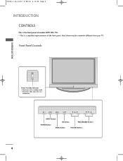
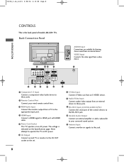
I This is switched on. Here shown may be somewhat different from your TV. Front Panel Controls INTRODUCTION Power/Standby Indicator • illuminates red in standby mode. • illuminates white when the set is a simplified representation of models 42PC1RV* TVs. INPUT MENU OK VOL PR INPUT MENU OK VOL PR INPUT MENU OK VOL PR INPUT Button OK Button PROGRAMME Buttons POWER Button MENU Button VOLUME Buttons 4 0323G_1-en_rev01 2/28/06 4:12 PM Page 4 INTRODUCTION CONTROLS This is the front panel of the front panel.
I This is switched on. Here shown may be somewhat different from your TV. Front Panel Controls INTRODUCTION Power/Standby Indicator • illuminates red in standby mode. • illuminates white when the set is a simplified representation of models 42PC1RV* TVs. INPUT MENU OK VOL PR INPUT MENU OK VOL PR INPUT MENU OK VOL PR INPUT Button OK Button PROGRAMME Buttons POWER Button MENU Button VOLUME Buttons 4 0323G_1-en_rev01 2/28/06 4:12 PM Page 4 INTRODUCTION CONTROLS This is the front panel of the front panel.
Owners Manual
Page 8
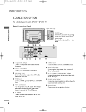
...the set. 7 S-Video Input Connect S-Video out from an S-VIDEO device. 8 Audio/Video Input Connect audio/video output from a PC to the appropriate input port. 4 HDMI Input Connect a HDMI signal to HDMI port with HDMI cable. 5 Power Cord Socket This TV operates on an AC power. The voltage is the back panel of the control devices to the RS-232C jack. 10 Variable Audio Output Connect an external amplifier or add a subwoofer to your wired remote control here. 3 RGB/Audio Input Connect the monitor output from an external device to these jacks. 2 Remote Control Port Connect your surround sound...
...the set. 7 S-Video Input Connect S-Video out from an S-VIDEO device. 8 Audio/Video Input Connect audio/video output from a PC to the appropriate input port. 4 HDMI Input Connect a HDMI signal to HDMI port with HDMI cable. 5 Power Cord Socket This TV operates on an AC power. The voltage is the back panel of the control devices to the RS-232C jack. 10 Variable Audio Output Connect an external amplifier or add a subwoofer to your wired remote control here. 3 RGB/Audio Input Connect the monitor output from an external device to these jacks. 2 Remote Control Port Connect your surround sound...
Owners Manual
Page 10
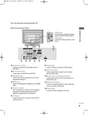
... stereo sound from a PC to the appropriate input port. 4 HDMI Input Connect a HDMI signal to HDMI port with HDMI cable. 5 Power Cord Socket This TV operates on an AC power. The voltage is the back panel of the control devices to the RS-232C jack. 10 Variable Audio Output Connect an external amplifier or add a subwoofer to your wired remote control here. 3 RGB/Audio Input Connect the monitor output from an external device. VIDEO Input Connects the video signal from a video AC IN AV IN 2 device. 1 COMPONENT IN VIDEO AUDIO...
... stereo sound from a PC to the appropriate input port. 4 HDMI Input Connect a HDMI signal to HDMI port with HDMI cable. 5 Power Cord Socket This TV operates on an AC power. The voltage is the back panel of the control devices to the RS-232C jack. 10 Variable Audio Output Connect an external amplifier or add a subwoofer to your wired remote control here. 3 RGB/Audio Input Connect the monitor output from an external device. VIDEO Input Connects the video signal from a video AC IN AV IN 2 device. 1 COMPONENT IN VIDEO AUDIO...
Owners Manual
Page 11
... set. 7 S-Video Input Connect S-Video out from an S-VIDEO device. 8 Audio/Video Input Connect audio/video output from an external device to these jacks. 2 Remote Control Port Connect your surround sound system. 11 Antenna Input Connect over-the-air signals to HDMI port with HDMI cable. 5 Power Cord Socket This TV operates on the Specifications page. 0323G_1-en_rev01 2/28/06 4:12 PM Page 9 INTRODUCTION This is indicated on an AC power. L/MONO VIDEO VIDEO Input Connects the video signal from an external device. The voltage is the back panel of the control...
... set. 7 S-Video Input Connect S-Video out from an S-VIDEO device. 8 Audio/Video Input Connect audio/video output from an external device to these jacks. 2 Remote Control Port Connect your surround sound system. 11 Antenna Input Connect over-the-air signals to HDMI port with HDMI cable. 5 Power Cord Socket This TV operates on the Specifications page. 0323G_1-en_rev01 2/28/06 4:12 PM Page 9 INTRODUCTION This is indicated on an AC power. L/MONO VIDEO VIDEO Input Connects the video signal from an external device. The voltage is the back panel of the control...

Owners Manual
Page 21
... VCR for viewing. Match the jack colors (Video = yellow, Audio Left = white, and Audio Right = red). 2 Insert a video tape into the VCR and press PLAY on the VCR. (Refer to AV IN2, select AV2 input source. (except 42PC3RV*) VARIABLE AUDIO OUT ANTENNA IN VCR ANT IN IN S-VIDEO (R) AUDIO (L) VIDEO OUTPUT SWITCH OUT 34 ANT OUT AV IN 3 S-VIDEO VIDEO ( ) AUDIO 1 COMPONENT IN VIDEO AUDIO 1 2 AV OUT AV IN 1 S-VIDEO VIDEO (MONO) AUDIO ! If connected to the VCR owner's manual.) 3 Select AV1 input source using the INPUT button on the screen...
... VCR for viewing. Match the jack colors (Video = yellow, Audio Left = white, and Audio Right = red). 2 Insert a video tape into the VCR and press PLAY on the VCR. (Refer to AV IN2, select AV2 input source. (except 42PC3RV*) VARIABLE AUDIO OUT ANTENNA IN VCR ANT IN IN S-VIDEO (R) AUDIO (L) VIDEO OUTPUT SWITCH OUT 34 ANT OUT AV IN 3 S-VIDEO VIDEO ( ) AUDIO 1 COMPONENT IN VIDEO AUDIO 1 2 AV OUT AV IN 1 S-VIDEO VIDEO (MONO) AUDIO ! If connected to the VCR owner's manual.) 3 Select AV1 input source using the INPUT button on the screen...

Owners Manual
Page 24
...PB PR S-VIDEO VIDEO ( ) AUDIO Y Pb Pr Video output ports Y COMPONENT IN B-Y R-Y VIDEO AUDIO on DVD player Y Cb Cr 1 Y PB PR 2 1 Connect the S-VIDEO output of the DVD to the S-VIDEO input on the set. 2 Connect the audio outputs of the DVD to the COMPONENT AUDIO jacks on the set . 3 Turn on the DVD player, insert a DVD. 4 Select AV3 input source with using the INPUT button on the remote control. 5 Refer to the DVD player's manual for operating instructions. NOTE G Component Input ports To get better picture quality, conn1ect a DVD player to the comp2 onent input ports as shown...
...PB PR S-VIDEO VIDEO ( ) AUDIO Y Pb Pr Video output ports Y COMPONENT IN B-Y R-Y VIDEO AUDIO on DVD player Y Cb Cr 1 Y PB PR 2 1 Connect the S-VIDEO output of the DVD to the S-VIDEO input on the set. 2 Connect the audio outputs of the DVD to the COMPONENT AUDIO jacks on the set . 3 Turn on the DVD player, insert a DVD. 4 Select AV3 input source with using the INPUT button on the remote control. 5 Refer to the DVD player's manual for operating instructions. NOTE G Component Input ports To get better picture quality, conn1ect a DVD player to the comp2 onent input ports as shown...

Owners Manual
Page 25
... a HDMI cable 1 Connect the HDMI output of the DVD to 1280x720p. COMPONENT IN 3 Refer to the HDMI IN jack on the set. 2 Select HDMI input source with using the INPUT button on the remote control. To get the best picture quality, adjust the output resolution of the DVD to the DVD player's manual for operating instruc- VIDEO AUDIO RGB IN (PC/DTV) HDMI IN REMOTE AUDIO IN CONTROL IN (RGB) VARIABLE AUDIO OUT RS-232C IN (CONTROL&SERVICE) 1 DVD HDMI-DVD OUTPUT ! tions. NOTE G TV can receive the video and audio signal simultaneously with using a HDMI cable.
... a HDMI cable 1 Connect the HDMI output of the DVD to 1280x720p. COMPONENT IN 3 Refer to the HDMI IN jack on the set. 2 Select HDMI input source with using the INPUT button on the remote control. To get the best picture quality, adjust the output resolution of the DVD to the DVD player's manual for operating instruc- VIDEO AUDIO RGB IN (PC/DTV) HDMI IN REMOTE AUDIO IN CONTROL IN (RGB) VARIABLE AUDIO OUT RS-232C IN (CONTROL&SERVICE) 1 DVD HDMI-DVD OUTPUT ! tions. NOTE G TV can receive the video and audio signal simultaneously with using a HDMI cable.
Owners Manual
Page 26
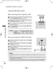
...SETUP STB (SET-TOP BOX) SETUP When connecting with a component cable 1 Connect the video outputs (Y, PB, PR) of the digital set-top box to the COMPONENT VIDEO jacks on the set. 2 Connect the audio output of the digital set-top box to the COMPONENT AUDIO jacks on the set. 3 Turn on the digital set-top box. (Refer to the owner's manual for the digital set-top box.) 4 Select HDMI input source with using the INPUT button on the remote control. NOTE G If the digital set -top box to the owner's manual for the digital set-top box.) 4 Select Component input source with using the INPUT button...
...SETUP STB (SET-TOP BOX) SETUP When connecting with a component cable 1 Connect the video outputs (Y, PB, PR) of the digital set-top box to the COMPONENT VIDEO jacks on the set. 2 Connect the audio output of the digital set-top box to the COMPONENT AUDIO jacks on the set. 3 Turn on the digital set-top box. (Refer to the owner's manual for the digital set-top box.) 4 Select HDMI input source with using the INPUT button on the remote control. NOTE G If the digital set -top box to the owner's manual for the digital set-top box.) 4 Select Component input source with using the INPUT button...
Owners Manual
Page 27
...SERVICE) CONNECTIONS & SETUP When connecting with a HDMI cable 1 Connect the HDMI output of the digital set-top box to the HDMI IN jack on the set. 2 Select HDMI input source with using a HDMI cable. ately. AV IN 3 S-VIDEO VIDEO ( ) AUDIO 25 G If the digital set-top box supports Auto HDMI function, output resolution of the digital set-top box will be automatically set to 1280x720p. To get the best picture quality, adjust the output resolution of the digital set-top box to 1280x720p. NOTE G TV can receive the video and audio signal simultaneously with using the INPUT button...
...SERVICE) CONNECTIONS & SETUP When connecting with a HDMI cable 1 Connect the HDMI output of the digital set-top box to the HDMI IN jack on the set. 2 Select HDMI input source with using a HDMI cable. ately. AV IN 3 S-VIDEO VIDEO ( ) AUDIO 25 G If the digital set-top box supports Auto HDMI function, output resolution of the digital set-top box will be automatically set to 1280x720p. To get the best picture quality, adjust the output resolution of the digital set-top box to 1280x720p. NOTE G TV can receive the video and audio signal simultaneously with using the INPUT button...

Owners Manual
Page 28
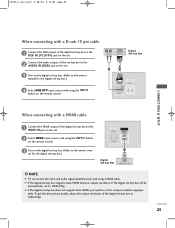
... remote control. (R) AUDIO (L) RGB-DTV OUTPUT PC 2 1 RGB IN (PC/DTV) HDMI IN REMOTE AUDIO IN CONTROL IN (RGB) VARIABLE AUDIO OUT RS-232C IN (CONTROL&SERVICE) CONNECTIONS & SETUP ! When connecting with a D-sub 15 pin cable 1 Connect the TV to the PC with the PC cable. 2 Connect the PC audio putput to the TV's AUDIO IN (RGB) input. 3 Turn on the PC. 4 Select RGB input source with the set 's screen for the PC mode, they provide the best picture...
... remote control. (R) AUDIO (L) RGB-DTV OUTPUT PC 2 1 RGB IN (PC/DTV) HDMI IN REMOTE AUDIO IN CONTROL IN (RGB) VARIABLE AUDIO OUT RS-232C IN (CONTROL&SERVICE) CONNECTIONS & SETUP ! When connecting with a D-sub 15 pin cable 1 Connect the TV to the PC with the PC cable. 2 Connect the PC audio putput to the TV's AUDIO IN (RGB) input. 3 Turn on the PC. 4 Select RGB input source with the set 's screen for the PC mode, they provide the best picture...

Owners Manual
Page 36
Manual config. Screen Auto config. VGA Mode ARC Reset DE F G OK MENU Screen menu Special Language Child lock ISM Method Low Power Set ID Demo * 42PC1RV* 42PC3RV* only DE F G OK MENU Special menu Time Clock Off time On time Auto sleep DE F G OK MENU Time menu TV MENU ! The OSD (On Screen Display) function enables you to adjust the screen status conveniently since it is shown in the sub or pull-down menu with the model. c. In the teletext mode, menus are not...
Manual config. Screen Auto config. VGA Mode ARC Reset DE F G OK MENU Screen menu Special Language Child lock ISM Method Low Power Set ID Demo * 42PC1RV* 42PC3RV* only DE F G OK MENU Special menu Time Clock Off time On time Auto sleep DE F G OK MENU Time menu TV MENU ! The OSD (On Screen Display) function enables you to adjust the screen status conveniently since it is shown in the sub or pull-down menu with the model. c. In the teletext mode, menus are not...

Owners Manual
Page 68
INPUT TV POWER INPUT ARC TV DVD VCR TEXT PIP SIZE POSTION PIP PR- PIP PR+ PIP INPUT LIST MENU I/II EXIT SLEEP OK 1 Press the M E N U button and then use D / E button to select the Screen menu. 2 Press the G button and then use D / E button to select ARC. 3 Press the G button and then use D / E button to select Spectacle, Full, Original, 4:3, 16:9, 14:9, Zoom1 or Zoom2. • Spectacle When your TV receives the wide screen signal, when selected it will adjust the picture horizontally, in...
INPUT TV POWER INPUT ARC TV DVD VCR TEXT PIP SIZE POSTION PIP PR- PIP PR+ PIP INPUT LIST MENU I/II EXIT SLEEP OK 1 Press the M E N U button and then use D / E button to select the Screen menu. 2 Press the G button and then use D / E button to select ARC. 3 Press the G button and then use D / E button to select Spectacle, Full, Original, 4:3, 16:9, 14:9, Zoom1 or Zoom2. • Spectacle When your TV receives the wide screen signal, when selected it will adjust the picture horizontally, in...
Owners Manual
Page 72
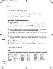
... the component responds properly. The remote control button of desired device is lighted. 3 Press the MENU and MUTE buttons simultaneously, the remote control is ready to be found on the following pages. Programming code numbers for the corresponding component can be programmed for the code. 4 Enter a code number using the number buttons on the component to be programmed to operate most remote-controllable devices of other manufacturers. Again, if the code is a multi-brand or a universal remote. 0323G_2...
... the component responds properly. The remote control button of desired device is lighted. 3 Press the MENU and MUTE buttons simultaneously, the remote control is ready to be found on the following pages. Programming code numbers for the corresponding component can be programmed for the code. 4 Enter a code number using the number buttons on the component to be programmed to operate most remote-controllable devices of other manufacturers. Again, if the code is a multi-brand or a universal remote. 0323G_2...

Owners Manual
Page 74
.... I Check antenna (Change the direction of possible interference. I This is normal, the image is weak, reorient antenna to +, - I Check for local interference such as an electrical appliance or power tool. Picture appears slow- I Test the wall power outlet, plug another channel. Please ly after five minutes. I Are the video cables installed properly? pictures APPENDIX 72 I Check the power control settings. I Correct remote operating mode set ? I Is the sleep timer set : TV, VCR etc.? bars or picture shaking...
.... I Check antenna (Change the direction of possible interference. I This is normal, the image is weak, reorient antenna to +, - I Check for local interference such as an electrical appliance or power tool. Picture appears slow- I Test the wall power outlet, plug another channel. Please ly after five minutes. I Are the video cables installed properly? pictures APPENDIX 72 I Check the power control settings. I Correct remote operating mode set ? I Is the sleep timer set : TV, VCR etc.? bars or picture shaking...

Service Manual
Page 5
... on the component side of the circuit board. 1. Power Output, Transistor Device Removal/Replacement 1. Remove defective diode by clipping its leads as close as the solder melts. 2. Bend into a "U" shape the end of each transistor lead, and clip off any printed circuit board will not exist if the jumper wire opens. 2. This technique involves the installation of a jumper...
... on the component side of the circuit board. 1. Power Output, Transistor Device Removal/Replacement 1. Remove defective diode by clipping its leads as close as the solder melts. 2. Bend into a "U" shape the end of each transistor lead, and clip off any printed circuit board will not exist if the jumper wire opens. 2. This technique involves the installation of a jumper...
Service Manual
Page 12
... isolation transformer. PCB assembly adjustment 4.1 PCB assembly adjustment method (Using VCTP Download program) 4.1.1.Download program installation (1) Extract a Zip file *LPT SETTING - Specification 2.1 Because this is not a hot chassis, it is applied all of White Balance. • Factoring Option Data input. 4. Delay => 1 - Adjustment items 3.1 PCB assembly adjustment items • Download the VCTP main software (IC601,VCPT) • Channel memory (IC603,EEPROM) • Colorcarrier Adjustment LPT Port Driver (LptDrv) Setups : Program Files > Micronas > Visual I2C...
... isolation transformer. PCB assembly adjustment 4.1 PCB assembly adjustment method (Using VCTP Download program) 4.1.1.Download program installation (1) Extract a Zip file *LPT SETTING - Specification 2.1 Because this is not a hot chassis, it is applied all of White Balance. • Factoring Option Data input. 4. Delay => 1 - Adjustment items 3.1 PCB assembly adjustment items • Download the VCTP main software (IC601,VCPT) • Channel memory (IC603,EEPROM) • Colorcarrier Adjustment LPT Port Driver (LptDrv) Setups : Program Files > Micronas > Visual I2C...

Service Manual
Page 17
... Color Bar) (3) Push the button change and select the Channel memory data (4) Check the communication is OK message. (5) Push the Update NVM from File b. Use the proper cables below for EDID Download * Caution: - S/W program download (1) Connect the download jig to LCD Module, especially be opened. 4.1.3. Use the proper signal cable for EDID Writing - 17 - Never connect HDMI & D-SUB Cable at the same time. - push the "adj" key in the adjustment remocon. 4.2 SET assembly adjustment method...
... Color Bar) (3) Push the button change and select the Channel memory data (4) Check the communication is OK message. (5) Push the Update NVM from File b. Use the proper cables below for EDID Download * Caution: - S/W program download (1) Connect the download jig to LCD Module, especially be opened. 4.1.3. Use the proper signal cable for EDID Writing - 17 - Never connect HDMI & D-SUB Cable at the same time. - push the "adj" key in the adjustment remocon. 4.2 SET assembly adjustment method...

Service Manual
Page 20
... is updated.) 35 MODE 36 PIP 37 TILT 38 0~9 Used as video, voice, function or channel. To adjust the screen voltage (automatic): In-start turbo picture 12 IN-START To enter adjustment mode when manufacturing the TV sets. SVC REMOCON NO KEY FUNTION REAMARK 1 POWER To turn the TV on or off the teletext mode 9 TV/AV To select an external input for the TV screen 10 TURBO SOUND...
... is updated.) 35 MODE 36 PIP 37 TILT 38 0~9 Used as video, voice, function or channel. To adjust the screen voltage (automatic): In-start turbo picture 12 IN-START To enter adjustment mode when manufacturing the TV sets. SVC REMOCON NO KEY FUNTION REAMARK 1 POWER To turn the TV on or off the teletext mode 9 TV/AV To select an external input for the TV screen 10 TURBO SOUND...


