

User Manual
Page 2
... contact the manufacturer or the nearest authorized repair service provider for replacement. If the power cable is easily accessible after installation. The power supply cord is OFF. Ensure that it from the wall outlet. There are dangerous. Contact your personal safety, however improper use may result in the specifications of this display. If you use , and servicing. Keep children from a power source indicated in a shock or fire hazard...
... contact the manufacturer or the nearest authorized repair service provider for replacement. If the power cable is easily accessible after installation. The power supply cord is OFF. Ensure that it from the wall outlet. There are dangerous. Contact your personal safety, however improper use may result in the specifications of this display. If you use , and servicing. Keep children from a power source indicated in a shock or fire hazard...

User Manual
Page 3
... anything hard as Red, Green or Blue spots on the display screen because over a radiator or heat source. If possible, use an aerosol directly on the screen. If used under any mode except the recommended resolution, some afterimages. However, this may result in enclosure unless proper ventilation is characteristic of the fixed-resolution LCD panel. Do not use the recommended resolution to obtain the best image quality for your...
... anything hard as Red, Green or Blue spots on the display screen because over a radiator or heat source. If possible, use an aerosol directly on the screen. If used under any mode except the recommended resolution, some afterimages. However, this may result in enclosure unless proper ventilation is characteristic of the fixed-resolution LCD panel. Do not use the recommended resolution to obtain the best image quality for your...

User Manual
Page 4
.... 2. Hook Removing the stand base 1. Insert the hooks into slots. Bottom Latch Important This illustration depicts the general model of the monitor. 3. Once you connect the stand base, try not to the monitor, the computer system, and other attached devices is turned off. The product may differ from the items shown in the picture. Place the monitor with its front facing downward on the stand base...
.... 2. Hook Removing the stand base 1. Insert the hooks into slots. Bottom Latch Important This illustration depicts the general model of the monitor. 3. Once you connect the stand base, try not to the monitor, the computer system, and other attached devices is turned off. The product may differ from the items shown in the picture. Place the monitor with its front facing downward on the stand base...

User Manual
Page 5
A4 Adjust the height. PUSH PUSH PUSH PUSH Button Ergonomic It is recommended that in various ways for maximum comfort. Tilt Range : -5˚~20˚ Height Range : maximun 2.76 inch (70.0mm) 70.0mm PUSH PUSH To adjust height of monitor Push down the top of the monitor should not exceed 5 degrees. Connecting the Display Positioning your display Adjust the position of the panel in order to maintain an ergonomic and comfortable viewing position, the forward tilt angle of monitor While pressing the PUSH button.
A4 Adjust the height. PUSH PUSH PUSH PUSH Button Ergonomic It is recommended that in various ways for maximum comfort. Tilt Range : -5˚~20˚ Height Range : maximun 2.76 inch (70.0mm) 70.0mm PUSH PUSH To adjust height of monitor Push down the top of the monitor should not exceed 5 degrees. Connecting the Display Positioning your display Adjust the position of the panel in order to maintain an ergonomic and comfortable viewing position, the forward tilt angle of monitor While pressing the PUSH button.
User Manual
Page 6
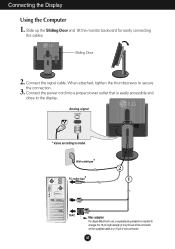
... PUSH 2. Analog signal * Varies according to model. * Wall-outlet type * PC-outlet type PUSH 2 1 PC MAC Mac adapter For Apple Macintosh use, a separate plug adapter is easily accessible and close to the display. Slide up the Sliding Door and tilt the monitor backward for easily connecting the cables. A5 Connecting the Display Using the Computer 1. When attached, tighten the thumbscrews to a 15 pin 2 row connector. Connect the power cord into a proper power outlet...
... PUSH 2. Analog signal * Varies according to model. * Wall-outlet type * PC-outlet type PUSH 2 1 PC MAC Mac adapter For Apple Macintosh use, a separate plug adapter is easily accessible and close to the display. Slide up the Sliding Door and tilt the monitor backward for easily connecting the cables. A5 Connecting the Display Using the Computer 1. When attached, tighten the thumbscrews to a 15 pin 2 row connector. Connect the power cord into a proper power outlet...
User Manual
Page 7
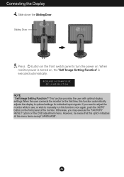
... option initializes all the menu items except 'LANGUAGE'. However, be aware that this function automatically adjusts the display to turn the power on , the 'Self Image Setting Function' is turned on . A6 Slide down the Sliding Door. Connecting the Display 4. Sliding Door PUSH PUSH 5. Press button on the OSD adjustment menu. This function provides the user with optimal display settings.When the user connects the monitor for individual input signals. When monitor power is executed automatically.
... option initializes all the menu items except 'LANGUAGE'. However, be aware that this function automatically adjusts the display to turn the power on , the 'Self Image Setting Function' is turned on . A6 Slide down the Sliding Door. Connecting the Display 4. Sliding Door PUSH PUSH 5. Press button on the OSD adjustment menu. This function provides the user with optimal display settings.When the user connects the monitor for individual input signals. When monitor power is executed automatically.

User Manual
Page 8
... information, refer to lock the current control settings, so that they cannot be inadvertently changed. OSD LOCKED/UNLOCKED This function allows you to page A14 LIGHT VIEW 12 DAY TEXT MENU - + SET A7 Use these buttons to enter or exit the On Screen Display. Control Panel Functions Front Panel Controls Bottom - + MENU LightView SET/AUTO Control MENU Button OSD VERROUILLAGE OSD DEVERROUILLAGEE - + Buttons Function Use this button to select or adjust functions in the On Screen Display. Press and hold the MENU button for 5 seconds.
... information, refer to lock the current control settings, so that they cannot be inadvertently changed. OSD LOCKED/UNLOCKED This function allows you to page A14 LIGHT VIEW 12 DAY TEXT MENU - + SET A7 Use these buttons to enter or exit the On Screen Display. Control Panel Functions Front Panel Controls Bottom - + MENU LightView SET/AUTO Control MENU Button OSD VERROUILLAGE OSD DEVERROUILLAGEE - + Buttons Function Use this button to select or adjust functions in the On Screen Display. Press and hold the MENU button for 5 seconds.

User Manual
Page 9
... Indicator lights up green when the display operates normally. If the display is 15 inch monitor : 1024x768 17 inch monitor : 1280x1024 REGLAGE AUTOMATIQUE DE L'IMAGE Use this button to enter a selection in DPM (Energy Saving) mode, this indicator color changes to the ideal settings for the current screen resolution size (display mode). The best display mode is in the On Screen Display. AUTO IMAGE ADJUSTMENT When adjusting your display image to amber. Control Panel Functions Control SET/AUTO Button Power Button Power (DPMS) Indicator Function Use this button to turn the display...
... Indicator lights up green when the display operates normally. If the display is 15 inch monitor : 1024x768 17 inch monitor : 1280x1024 REGLAGE AUTOMATIQUE DE L'IMAGE Use this button to enter a selection in DPM (Energy Saving) mode, this indicator color changes to the ideal settings for the current screen resolution size (display mode). The best display mode is in the On Screen Display. AUTO IMAGE ADJUSTMENT When adjusting your display image to amber. Control Panel Functions Control SET/AUTO Button Power Button Power (DPMS) Indicator Function Use this button to turn the display...

User Manual
Page 10
... the image size, position and operating parameters of the available adjustments and selections you exit the menu or open , once you have made an adjustment the monitor automatically save any adjustments you have made, even if you can make an adjustment and then wait for at least 30 minutes before making image adjustments. A9 Use the - / + Buttons to adjust the image to exit from the OSD. A short example is quick and...
... the image size, position and operating parameters of the available adjustments and selections you exit the menu or open , once you have made an adjustment the monitor automatically save any adjustments you have made, even if you can make an adjustment and then wait for at least 30 minutes before making image adjustments. A9 Use the - / + Buttons to adjust the image to exit from the OSD. A short example is quick and...

User Manual
Page 11
... menu Sub-menu PICTURE BRIGHTNESS CONTRAST GAMMA COLOR PRESET RED GREEN POSITION BLUE H POSITION V POSITION TRACKING CLOCK PHASE FACTORY FACTORY RESET RESET WHITE BALANCE SETUP LANGUAGE OSD H POSITION OSD V POSITION LIGHTVIEW DAY TEXT/MOVIE/PHOTO NIGHT TEXT/MOVIE/PHOTO USER1/2 NORMAL Reference To adjust the brightness, contrast and gamma of the screen To customize the color of the screen To adjust the position of the screen To improve the clarity and stability of the screen To restore the default settings To customize the screen status for a user...
... menu Sub-menu PICTURE BRIGHTNESS CONTRAST GAMMA COLOR PRESET RED GREEN POSITION BLUE H POSITION V POSITION TRACKING CLOCK PHASE FACTORY FACTORY RESET RESET WHITE BALANCE SETUP LANGUAGE OSD H POSITION OSD V POSITION LIGHTVIEW DAY TEXT/MOVIE/PHOTO NIGHT TEXT/MOVIE/PHOTO USER1/2 NORMAL Reference To adjust the brightness, contrast and gamma of the screen To customize the color of the screen To adjust the position of the screen To improve the clarity and stability of the screen To restore the default settings To customize the screen status for a user...

User Manual
Page 12
Listed below are the icons, icon names, and icon descriptions of the all items shown on the monitor may differ from the manual. Menu Name Icons PICTURE Sub-menus Button Tip 50 50 0 MENU - + SET MENU : Exit - + : Adjust (Decrease/Increase) SET : Enter : Select another sub-menu NOTE OSD (On Screen Display) menu languages on the Menu. Press the MENU Button, then the main menu of selecting and adjusting an item using the OSD system. A11 On Screen Display(OSD) Selection and Adjustment You were introduced to the procedure of the OSD appears.
Listed below are the icons, icon names, and icon descriptions of the all items shown on the monitor may differ from the manual. Menu Name Icons PICTURE Sub-menus Button Tip 50 50 0 MENU - + SET MENU : Exit - + : Adjust (Decrease/Increase) SET : Enter : Select another sub-menu NOTE OSD (On Screen Display) menu languages on the Menu. Press the MENU Button, then the main menu of selecting and adjusting an item using the OSD system. A11 On Screen Display(OSD) Selection and Adjustment You were introduced to the procedure of the OSD appears.

User Manual
Page 13
...On Screen Display(OSD) Selection and Adjustment Main menu PICTURE BRIGHTNESS Sub menu BRIGHTNESS CONTRAST 50 50 GAMMA 0 MENU - + SET MENU : Exit +- : Decrease : Increase SET : Select another sub-menu COLOR PRESET PRESET 6500K 9300K 50 50 50 RED GREEN MENU - + SET BLUE MENU : Exit +- : Decrease : Increase SET : Select another sub-menu A12 To adjust the contrast of the screen. Set your own green color levels. To move image up and down. 50 MENU - + SET MENU : Exit +- : Decrease : Increase SET : Select another sub-menu POSITION H POSITION H POSITION...
...On Screen Display(OSD) Selection and Adjustment Main menu PICTURE BRIGHTNESS Sub menu BRIGHTNESS CONTRAST 50 50 GAMMA 0 MENU - + SET MENU : Exit +- : Decrease : Increase SET : Select another sub-menu COLOR PRESET PRESET 6500K 9300K 50 50 50 RED GREEN MENU - + SET BLUE MENU : Exit +- : Decrease : Increase SET : Select another sub-menu A12 To adjust the contrast of the screen. Set your own green color levels. To move image up and down. 50 MENU - + SET MENU : Exit +- : Decrease : Increase SET : Select another sub-menu POSITION H POSITION H POSITION...

User Manual
Page 14
... video card is an analog signal. To adjust the focus of the OSD H POSITION window on the screen. Activate this function when white and black colors are present in which the control names are displayed. If the output of characters. ENGLISH MENU - 50 50 + SET OSD To adjust horizontal position of the display. If you want to video signal distortion. Using this does not improve the screen image, restore the factory default settings. On Screen Display(OSD) Selection and Adjustment Main menu TRACKING CLOCK Sub menu...
... video card is an analog signal. To adjust the focus of the OSD H POSITION window on the screen. Activate this function when white and black colors are present in which the control names are displayed. If the output of characters. ENGLISH MENU - 50 50 + SET OSD To adjust horizontal position of the display. If you want to video signal distortion. Using this does not improve the screen image, restore the factory default settings. On Screen Display(OSD) Selection and Adjustment Main menu TRACKING CLOCK Sub menu...

User Manual
Page 15
... USER 1 USER 2 User can preset the BRIGHTNESS, CONTRAST, GAMMA, and PRESET levels and save the YES value using the SET button and save them for later use. Select the sub-menu using the - /+ buttons. Menu Name LIGHT VIEW Icons 12 Sub-menu Name DAY TEXT MENU - + SET Main menu Sub menu Description LIGHTVIEW LIGHT VIEW 12 DAY NIGHT DAY TEXT MENU - + SET - + : Select another sub-menu LIGHT VIEW NORMAL This is under normal operating conditions. 12 NORMAL MENU - + SET A14 On Screen Display(OSD...
... USER 1 USER 2 User can preset the BRIGHTNESS, CONTRAST, GAMMA, and PRESET levels and save the YES value using the SET button and save them for later use. Select the sub-menu using the - /+ buttons. Menu Name LIGHT VIEW Icons 12 Sub-menu Name DAY TEXT MENU - + SET Main menu Sub menu Description LIGHTVIEW LIGHT VIEW 12 DAY NIGHT DAY TEXT MENU - + SET - + : Select another sub-menu LIGHT VIEW NORMAL This is under normal operating conditions. 12 NORMAL MENU - + SET A14 On Screen Display(OSD...
User Manual
Page 16
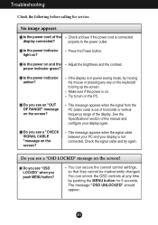
... power indicator light on . Is the power on the screen? If the display is out of horizontal or vertical frequency range of the display connected? This message appears when the signal cable between your PC and your display again. Do you see "OSD LOCKED" when you see a "CHECK SIGNAL CABLE "message on and the Adjust the brightness and the contrast. Troubleshooting Check the following before calling for 5 seconds. No image appears Is the power cord of the display...
... power indicator light on . Is the power on the screen? If the display is out of horizontal or vertical frequency range of the display connected? This message appears when the signal cable between your PC and your display again. Do you see "OSD LOCKED" when you see a "CHECK SIGNAL CABLE "message on and the Adjust the brightness and the contrast. Troubleshooting Check the following before calling for 5 seconds. No image appears Is the power cord of the display...

User Manual
Page 17
... horizontal bars using the H position and V position icon in the slot. Press the SET/AUTO button to automatically adjust your display image to the ideal setting. Settings. Troubleshooting Display image is incorrect Display Position is mono or abnormal. Press the SET/AUTO button to automatically adjust your display image to the ideal setting. If the results are unsatisfactory, adjust the image position using the PHASE icon in the on screen display. Check Control Panel --> Display --> Settings and see if the frequency or the resolution were changed. Make sure the video card...
... horizontal bars using the H position and V position icon in the slot. Press the SET/AUTO button to automatically adjust your display image to the ideal setting. Settings. Troubleshooting Display image is incorrect Display Position is mono or abnormal. Press the SET/AUTO button to automatically adjust your display image to the ideal setting. If the results are unsatisfactory, adjust the image position using the PHASE icon in the on screen display. Check Control Panel --> Display --> Settings and see if the frequency or the resolution were changed. Make sure the video card...

User Manual
Page 18
.... Do you installed the display driver? Be sure to check if the video card supports Plug&Play function. If LIGHTVIEW is selected for LIGHTVIEW. Troubleshooting Have you see an "Unrecognized monitor, Plug&Play (VESA DDC) monitor found" message? Have you can not be activated from the display driver CD (or diskette) that the NORMAL setting is set LIGHTVIEW to NORMAL. PICTURE and COLOR menus can also download the driver from the OSD menu?
.... Do you installed the display driver? Be sure to check if the video card supports Plug&Play function. If LIGHTVIEW is selected for LIGHTVIEW. Troubleshooting Have you see an "Unrecognized monitor, Plug&Play (VESA DDC) monitor found" message? Have you can not be activated from the display driver CD (or diskette) that the NORMAL setting is set LIGHTVIEW to NORMAL. PICTURE and COLOR menus can also download the driver from the OSD menu?

User Manual
Page 19
A18 Specifications L1530S H Display Sync Input Video Input Resolution Plug&Play Power Consumption Dimensions &Weight (with tilt stand) Tilt/Height Range Power Input Environmental Conditions Tilt Stand Signal cable Power cord 15 inches (38.1cm) Flat Panel Active matrix-TFT LCD Anti-Glare coating 15 inches viewable 0.3 mm pixel pitch Horizontal Freq. 30 - 63kHz (Automatic) Vertical Freq. 56 - 75Hz (Automatic) Input Form Separate TTL, Positive/Negative Signal Input Input Form 15 pin D-Sub Connector RGB Analog (0.7Vp-p/75ohm) Max Recommend VESA 1024 x 768@75Hz VESA 1024 x 768@60Hz ...
A18 Specifications L1530S H Display Sync Input Video Input Resolution Plug&Play Power Consumption Dimensions &Weight (with tilt stand) Tilt/Height Range Power Input Environmental Conditions Tilt Stand Signal cable Power cord 15 inches (38.1cm) Flat Panel Active matrix-TFT LCD Anti-Glare coating 15 inches viewable 0.3 mm pixel pitch Horizontal Freq. 30 - 63kHz (Automatic) Vertical Freq. 56 - 75Hz (Automatic) Input Form Separate TTL, Positive/Negative Signal Input Input Form 15 pin D-Sub Connector RGB Analog (0.7Vp-p/75ohm) Max Recommend VESA 1024 x 768@75Hz VESA 1024 x 768@60Hz ...

User Manual
Page 20
... Specifications L1730S H Display 17 inches (43.2cm) Flat Panel Active matrix-TFT LCD Anti-Glare coating 17 inches viewable 0.26 mm pixel pitch Sync Input Horizontal Freq. Input Form 30 - 83kHz (Automatic) 56 - 75Hz (Automatic) Separate TTL, Positive/Negative Composite TTL Positive/Negative SOG (Sync On Green) Video Input Resolution Signal Input Input Form Max Recommend 15 pin D-Sub Connector RGB Analog (0.7Vp-p/75ohm) VESA 1280 x 1024@75Hz VESA 1280 x 1024@60Hz Plug&Play DDC 2B Power Consumption Normal : 43W Stand...
... Specifications L1730S H Display 17 inches (43.2cm) Flat Panel Active matrix-TFT LCD Anti-Glare coating 17 inches viewable 0.26 mm pixel pitch Sync Input Horizontal Freq. Input Form 30 - 83kHz (Automatic) 56 - 75Hz (Automatic) Separate TTL, Positive/Negative Composite TTL Positive/Negative SOG (Sync On Green) Video Input Resolution Signal Input Input Form Max Recommend 15 pin D-Sub Connector RGB Analog (0.7Vp-p/75ohm) VESA 1280 x 1024@75Hz VESA 1280 x 1024@60Hz Plug&Play DDC 2B Power Consumption Normal : 43W Stand...

User Manual
Page 23
.... 3. How to another object (stand type and wall-mounted type. PUSH 2. Separate the stand base using a screwdriver as shown in the picture. 4. Install the VESA standrad wall mounting. VESA wall mounting Connected to Install the VESA Standard wall mounting This monitor meets VESA-compliant mounting interface pad specifications. 1. optional Connected to the VESA Wall Mounting Instruction Guide. Remove the Sliding Door. This monitor accepts a VESA-compliant mounting interface pad.-optional) For further information, refer to a locking cable that can be purchased separately at...
.... 3. How to another object (stand type and wall-mounted type. PUSH 2. Separate the stand base using a screwdriver as shown in the picture. 4. Install the VESA standrad wall mounting. VESA wall mounting Connected to Install the VESA Standard wall mounting This monitor meets VESA-compliant mounting interface pad specifications. 1. optional Connected to the VESA Wall Mounting Instruction Guide. Remove the Sliding Door. This monitor accepts a VESA-compliant mounting interface pad.-optional) For further information, refer to a locking cable that can be purchased separately at...


