

Owner's Manual
Page 1
Installation and Operating Guide | Warranty Model Number | L20V54S | LCD TV/Monitor table of Zenith Electronics Corporation Zenith and the lightning Z logo are registered trademarks of contents installer quick setup guide 5 page page 60 © Copyright 2007, LG Electronics U.S.A., Inc.
Installation and Operating Guide | Warranty Model Number | L20V54S | LCD TV/Monitor table of Zenith Electronics Corporation Zenith and the lightning Z logo are registered trademarks of contents installer quick setup guide 5 page page 60 © Copyright 2007, LG Electronics U.S.A., Inc.

Owner's Manual
Page 2
... against harmful interference when the equipment is operated in a residential installation. IT IS FORBIDDEN TO CONNECT THIS TV TO ANY TELECOMMUNICATION NETWORK / TELEPHONE. L20V54S SERIAL NO CAUTION RISK OF ELECTRIC SHOCK DO NOT OPEN CAUTION: TO REDUCE THE RISK OF ELECTRIC SHOCK ... the receiver is connected. •Consult the dealer or an experienced radio/TV technician for proper grounding and, in particular, specifies that may cause harmful interference to correct the interference by LG Electronics U.S.A., Inc. 2000 Millbrook Drive, Lincolnshire, IL 60069. REFER TO QUALIFIED...
... against harmful interference when the equipment is operated in a residential installation. IT IS FORBIDDEN TO CONNECT THIS TV TO ANY TELECOMMUNICATION NETWORK / TELEPHONE. L20V54S SERIAL NO CAUTION RISK OF ELECTRIC SHOCK DO NOT OPEN CAUTION: TO REDUCE THE RISK OF ELECTRIC SHOCK ... the receiver is connected. •Consult the dealer or an experienced radio/TV technician for proper grounding and, in particular, specifies that may cause harmful interference to correct the interference by LG Electronics U.S.A., Inc. 2000 Millbrook Drive, Lincolnshire, IL 60069. REFER TO QUALIFIED...
Owner's Manual
Page 3
...CAUTION: To avoid damage to the patient's bed where it can be reached by the patient. 2. DISCONNECTING DEVICE FROM MAINS: Main plug is : LG Electronics U.S.A., Inc., 2000 Millbrook Drive Lincolnshire, IL 60069, USA. The plug must remain readily operable. TO AVOID DEFEATING THE SAFEGUARDS THAT HAVE BEEN... AND YOUR NEW PRODUCT YOUR PRODUCT HAS BEEN MANUFACTURED AND TESTED WITH YOUR SAFETY IN MIND. However, they have no objects filled with the TV. - CAUTION: THESE SERVICING INSTRUCTIONS ARE FOR USE BY QUALIFIED SERVICE PERSONNEL ONLY. PAGE 3 Phone: 1-847-941-8000 WARNING: Apparatus shall ...
...CAUTION: To avoid damage to the patient's bed where it can be reached by the patient. 2. DISCONNECTING DEVICE FROM MAINS: Main plug is : LG Electronics U.S.A., Inc., 2000 Millbrook Drive Lincolnshire, IL 60069, USA. The plug must remain readily operable. TO AVOID DEFEATING THE SAFEGUARDS THAT HAVE BEEN... AND YOUR NEW PRODUCT YOUR PRODUCT HAS BEEN MANUFACTURED AND TESTED WITH YOUR SAFETY IN MIND. However, they have no objects filled with the TV. - CAUTION: THESE SERVICING INSTRUCTIONS ARE FOR USE BY QUALIFIED SERVICE PERSONNEL ONLY. PAGE 3 Phone: 1-847-941-8000 WARNING: Apparatus shall ...

Owner's Manual
Page 5
.../Teaching Setup 44 Installer Menu 45-50 Reference 50-53 L20V54S Aux Input Configuration/Troubleshooting . . . .54 Troubleshooting 55 Reference: Cloning Procedure Troubleshooting 56 Troubleshooting Flow Chart 57 TV Operation Check 58 Glossary of Terms 59 Installer Quick Setup ...be purchased separately, see your Zenith/LG dealer if you need an installer's remote and the LT2002 Quickset II Clone Programmer - LCD TV/Monitor Installation and Connections Setup Checklist 6 Installation/Connections Overview 7 VESA Standard TV Mounts 8 TV and other Equipment Hookup Antenna 9...
.../Teaching Setup 44 Installer Menu 45-50 Reference 50-53 L20V54S Aux Input Configuration/Troubleshooting . . . .54 Troubleshooting 55 Reference: Cloning Procedure Troubleshooting 56 Troubleshooting Flow Chart 57 TV Operation Check 58 Glossary of Terms 59 Installer Quick Setup ...be purchased separately, see your Zenith/LG dealer if you need an installer's remote and the LT2002 Quickset II Clone Programmer - LCD TV/Monitor Installation and Connections Setup Checklist 6 Installation/Connections Overview 7 VESA Standard TV Mounts 8 TV and other Equipment Hookup Antenna 9...
Owner's Manual
Page 6
...Installer's remote control available to use to set up all source equipment. Yes___ No___ LT2002 Quickset II Clone Programmer To copy the TV's setup, the installer will be used , AC Power source outlet, Antenna/Cable service connectors, any other additional required hardware, etc. ...copied to a standard 120V, 60 Hertz, AC power source. See page 14. Turn on the stand following the instructions supplied with the TV stand. Review TV Setup Options in the Installer's Menu Section The Installer's menu includes a number of Contents. 2. Is there a Zenith LT2002 Clone Programmer available...
...Installer's remote control available to use to set up all source equipment. Yes___ No___ LT2002 Quickset II Clone Programmer To copy the TV's setup, the installer will be used , AC Power source outlet, Antenna/Cable service connectors, any other additional required hardware, etc. ...copied to a standard 120V, 60 Hertz, AC power source. See page 14. Turn on the stand following the instructions supplied with the TV stand. Review TV Setup Options in the Installer's Menu Section The Installer's menu includes a number of Contents. 2. Is there a Zenith LT2002 Clone Programmer available...
Owner's Manual
Page 7
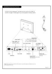
... up source equipment, see below and also refer to select the speaker output. *Note: If Pillow Speaker is selected, no Sound will be heard from TV speakers. shows pages to go to pillow speaker (12V DC 40mA) *Note: RS-232C, Update Switch and RS-232C Select Switch are reserved for equipment...
... up source equipment, see below and also refer to select the speaker output. *Note: If Pillow Speaker is selected, no Sound will be heard from TV speakers. shows pages to go to pillow speaker (12V DC 40mA) *Note: RS-232C, Update Switch and RS-232C Select Switch are reserved for equipment...
Owner's Manual
Page 8
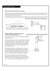
... SPEAKER AUDIO IN VIDEO IN CONTROL NORMAL (DTV) General Guidelines: Choosing a location for installing a VESA Standard Mount Typical Pedestal Type Mount with the TV stand that the wiring is capable of supporting the weight of VESA standard 100 mm mounts. If the mount will be used to the user... chosen should be appro-priate for drilling holes and have available the required power source as well as to create a potential hazard to mount the TV. For pedestal-type mounts, a sturdy surface on a wall, a typical wooden stud behind the wall board would be moved from one location to the...
... SPEAKER AUDIO IN VIDEO IN CONTROL NORMAL (DTV) General Guidelines: Choosing a location for installing a VESA Standard Mount Typical Pedestal Type Mount with the TV stand that the wiring is capable of supporting the weight of VESA standard 100 mm mounts. If the mount will be used to the user... chosen should be appro-priate for drilling holes and have available the required power source as well as to create a potential hazard to mount the TV. For pedestal-type mounts, a sturdy surface on a wall, a typical wooden stud behind the wall board would be moved from one location to the...

Owner's Manual
Page 9
... CABLE 300 TO 75 OHM ADAPTER The wire that connects a two-wire 300 ohm antenna to one end and a round opening with the Zenith LCD TV/Monitor. They are usually about an inch long with a wire sticking through the middle, and it screws onto the threaded jack on the other end.... Each end looks like a hex shaped nut with two screws on one of the TV. Antenna Hookup Connect an off -air antenna or cable service provider. The LCD TV/Monitor is not included with a wire sticking out on the back of the diagrams shown to the LCD...
... CABLE 300 TO 75 OHM ADAPTER The wire that connects a two-wire 300 ohm antenna to one end and a round opening with the Zenith LCD TV/Monitor. They are usually about an inch long with a wire sticking through the middle, and it screws onto the threaded jack on the other end.... Each end looks like a hex shaped nut with two screws on one of the TV. Antenna Hookup Connect an off -air antenna or cable service provider. The LCD TV/Monitor is not included with a wire sticking out on the back of the diagrams shown to the LCD...
Owner's Manual
Page 10
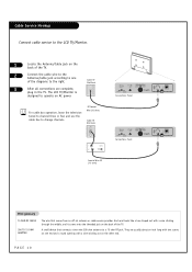
... TO 75 OHM ADAPTER The wire that connects a two-wire 300 ohm antenna to a 75 ohm RF jack. They are complete, plug in the TV. The LCD TV/Monitor is designed to change channels. Each end looks like a hex shaped nut with a wire sticking out on the other end. A small device that... comes from an off-air antenna or cable service provider. Cable Service Hookup Connect cable service to the LCD TV/Monitor. 1 Locate the Antenna/Cable jack on the back of the TV. 2 Connect the cable wire to the Antenna/Cable jack according to one end and a round opening with a wire sticking...
... TO 75 OHM ADAPTER The wire that connects a two-wire 300 ohm antenna to a 75 ohm RF jack. They are complete, plug in the TV. The LCD TV/Monitor is designed to change channels. Each end looks like a hex shaped nut with a wire sticking out on the other end. A small device that... comes from an off-air antenna or cable service provider. Cable Service Hookup Connect cable service to the LCD TV/Monitor. 1 Locate the Antenna/Cable jack on the back of the TV. 2 Connect the cable wire to the Antenna/Cable jack according to one end and a round opening with a wire sticking...
Owner's Manual
Page 11
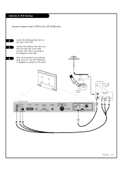
... of the VCR. 2 Connect the antenna wire that runs from the wall jack to the VCR. The LCD TV/Monitor is designed to the right. 3 After all connections are complete, plug in the TV. Round or Flat wire (300 ohm) Connections Panel VIDEO RS-232C UPDATE RS-232C SELECT FUTURE USE SPEAKER... AUDIO IN VIDEO IN CONTROL NORMAL (DTV) 300/75ohm Adapter VCR Back Panel PAGE 11 Antenna & VCR Hookup Connect antenna and a VCR to the LCD TV/Monitor. 1 Locate the Antenna/Cable jack on AC power.
... of the VCR. 2 Connect the antenna wire that runs from the wall jack to the VCR. The LCD TV/Monitor is designed to the right. 3 After all connections are complete, plug in the TV. Round or Flat wire (300 ohm) Connections Panel VIDEO RS-232C UPDATE RS-232C SELECT FUTURE USE SPEAKER... AUDIO IN VIDEO IN CONTROL NORMAL (DTV) 300/75ohm Adapter VCR Back Panel PAGE 11 Antenna & VCR Hookup Connect antenna and a VCR to the LCD TV/Monitor. 1 Locate the Antenna/Cable jack on AC power.
Owner's Manual
Page 12
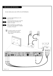
The LCD TV/Monitor is designed to change channels. For cable box operation, leave the VCR and the television tuned to channel three or four and...the cable service wire to the VCR. 2 Connect other wires according to the diagram to the LCD TV/Monitor. 1 Locate the Antenna/Cable jack on AC power. Cable TV Wall Jack Cable TV Wall Jack Cable Box Connections Panel VIDEO RS-232C UPDATE RS-232C SELECT FUTURE USE SPEAKER SWITCH PILLOW ...PAGE 12 Cable Service with VCR Hookup Connect cable service and a VCR to the right. 3 After all connections are complete, plug in the TV.
The LCD TV/Monitor is designed to change channels. For cable box operation, leave the VCR and the television tuned to channel three or four and...the cable service wire to the VCR. 2 Connect other wires according to the diagram to the LCD TV/Monitor. 1 Locate the Antenna/Cable jack on AC power. Cable TV Wall Jack Cable TV Wall Jack Cable Box Connections Panel VIDEO RS-232C UPDATE RS-232C SELECT FUTURE USE SPEAKER SWITCH PILLOW ...PAGE 12 Cable Service with VCR Hookup Connect cable service and a VCR to the right. 3 After all connections are complete, plug in the TV.
Owner's Manual
Page 13
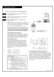
... lines are no sound will be heard from pin 4) with a low-impedance pad-type volume control. 6 External Channel Down switch. Purpose 1 External TV On/Off switch. 2 (Not used in the control lines.) SPEAKER SWITCH PILLOW NORMAL SPEAKER SPEAKER Pillow speaker not included with Mechanical Switches Pin 4 (...the AC power line and earth ground. (Opto-isolators isolate the control lines, and a transformer isolates the audio. Controlling the TV with Serial Data The TV is identical to earth ground is being controlled by certain brands of fire if used .) 3 External Channel Up switch or ...
... lines are no sound will be heard from pin 4) with a low-impedance pad-type volume control. 6 External Channel Down switch. Purpose 1 External TV On/Off switch. 2 (Not used in the control lines.) SPEAKER SWITCH PILLOW NORMAL SPEAKER SPEAKER Pillow speaker not included with Mechanical Switches Pin 4 (...the AC power line and earth ground. (Opto-isolators isolate the control lines, and a transformer isolates the audio. Controlling the TV with Serial Data The TV is identical to earth ground is being controlled by certain brands of fire if used .) 3 External Channel Up switch or ...

Owner's Manual
Page 14
AC IN HDMI IN VIDEO L R AUDIO IN VIDEO IN RS-232C UPDATE RS-232C SELECT FUTURE USE CONTROL NORMAL (DTV) SPEAKER SWITCH PILLOW NORMAL SPEAKER SPEAKER AC Power Cord PAGE 14 AC Power Cord Hookup The LCD TV/Monitor is designed to the LCD TV/Monitor. Power Cord Hookup Connect the AC power cord directly to operate on 120V AC power. 1 Locate the AC Power Cord input socket on the back of the LCD TV/Monitor. 2 Insert the AC power cord connector into the AC Socket on the TV as shown below.
AC IN HDMI IN VIDEO L R AUDIO IN VIDEO IN RS-232C UPDATE RS-232C SELECT FUTURE USE CONTROL NORMAL (DTV) SPEAKER SWITCH PILLOW NORMAL SPEAKER SPEAKER AC Power Cord PAGE 14 AC Power Cord Hookup The LCD TV/Monitor is designed to the LCD TV/Monitor. Power Cord Hookup Connect the AC power cord directly to operate on 120V AC power. 1 Locate the AC Power Cord input socket on the back of the LCD TV/Monitor. 2 Insert the AC power cord connector into the AC Socket on the TV as shown below.
Owner's Manual
Page 15
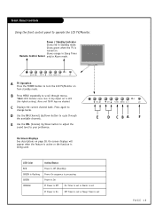
...D Use the CH (Channel) Up/Down button to cycle through menus. *Note: With Installer menu item 11 Key Defeat set to turn the LCD TV/Monitor on page 18. LED Color RED GREEN is flashing GREEN ORANGE Action/Status Power is Off (Standby) Power On sequence is processing Power is ... again to your preference. Glows green when the TV is set or Sleep Timer is turned on. VOL CH TV/AV MENU / I A TV Operation Press the POWER button to 000 (the default setting), Menu and TV/AV keys are disabled. VOL CH TV/AV MENU / I VOL CH TV/AV MENU / I E D C BA F On-Screen Displays See ...
...D Use the CH (Channel) Up/Down button to cycle through menus. *Note: With Installer menu item 11 Key Defeat set to turn the LCD TV/Monitor on page 18. LED Color RED GREEN is flashing GREEN ORANGE Action/Status Power is Off (Standby) Power On sequence is processing Power is ... again to your preference. Glows green when the TV is set or Sleep Timer is turned on. VOL CH TV/AV MENU / I A TV Operation Press the POWER button to 000 (the default setting), Menu and TV/AV keys are disabled. VOL CH TV/AV MENU / I VOL CH TV/AV MENU / I E D C BA F On-Screen Displays See ...
Owner's Manual
Page 16
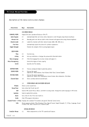
...V-Chip, Language, Sound Format, Time, Date, Channel Icon, Channel Label. Sleep Timer Sets a time the TV will turn itself on. Captions Selects Caption/Text options. Alarm Set a time for the TV to scroll through using Channel Up/Down. 22 Manually picks and chooses which active channels will appear when...MENU Auto Program Channel List Channel Label Fine Tune Signal Strength ON-SCREEN MENUS Adjusts the basic operational features of the TV. 21 Automatically finds and stores active channels to turn off. Change the audio language in analog mode. Set ID Specifies the...
...V-Chip, Language, Sound Format, Time, Date, Channel Icon, Channel Label. Sleep Timer Sets a time the TV will turn itself on. Captions Selects Caption/Text options. Alarm Set a time for the TV to scroll through using Channel Up/Down. 22 Manually picks and chooses which active channels will appear when...MENU Auto Program Channel List Channel Label Fine Tune Signal Strength ON-SCREEN MENUS Adjusts the basic operational features of the TV. 21 Automatically finds and stores active channels to turn off. Change the audio language in analog mode. Set ID Specifies the...
Owner's Manual
Page 17
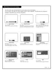
...VOLUME. In this manual, the OSD (On Screen Displays shown) may be different. OK Exit Alarm Display Press the ALARM. Displays available TV channels. DIGITAL 84-1 1920*1080@60Hz No Time Information No Title N/A Dolby Digital Korean N/A INFO Press the INFO. The following are ...Service1 Caption Display Press the CC. Off Adjust Min. Sets a time to automatically turn itself on or off and shows remaining time before TV shutoff. Channel Antenna Channel List (1/1) Add Auto Program ANALOG 14 Channel Label Channel List Fine Tune ANALOG 15 ANALOG 16 DIGITAL 7-1 DIGITAL...
...VOLUME. In this manual, the OSD (On Screen Displays shown) may be different. OK Exit Alarm Display Press the ALARM. Displays available TV channels. DIGITAL 84-1 1920*1080@60Hz No Time Information No Title N/A Dolby Digital Korean N/A INFO Press the INFO. The following are ...Service1 Caption Display Press the CC. Off Adjust Min. Sets a time to automatically turn itself on or off and shows remaining time before TV shutoff. Channel Antenna Channel List (1/1) Add Auto Program ANALOG 14 Channel Label Channel List Fine Tune ANALOG 15 ANALOG 16 DIGITAL 7-1 DIGITAL...
Owner's Manual
Page 18
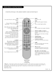
... the picture remains. CHANNEL (-/+) Tunes to access closed captions. Left position = Bed 1. Bed 2 switch must correspond to the setting in the TV's Installer Menu. Right Position = Bed 2. NUMBER KEYPAD Selects channels directly and enters numerical values for navigating menus. Analog channels do . MENU Press... set V-Chip blocks to restrict both analog and digital programming. • Aux Channel allows the guest to the previous channel viewed. POWER Turns TV On or Off. Bed 2 switch on -screen menu. On the patient's remote, the Bed 1 or Bed 2 position can be selected ...
... the picture remains. CHANNEL (-/+) Tunes to access closed captions. Left position = Bed 1. Bed 2 switch must correspond to the setting in the TV's Installer Menu. Right Position = Bed 2. NUMBER KEYPAD Selects channels directly and enters numerical values for navigating menus. Analog channels do . MENU Press... set V-Chip blocks to restrict both analog and digital programming. • Aux Channel allows the guest to the previous channel viewed. POWER Turns TV On or Off. Bed 2 switch on -screen menu. On the patient's remote, the Bed 1 or Bed 2 position can be selected ...
Owner's Manual
Page 19
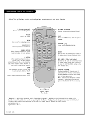
... on -screen menu items and change the selected option. MUTE Turns sound Off and On, while the picture remains. Select on the back of the TV as a source). [-] BUTTON When selecting a digital broadcast channel, key in the Installer's menu. FLASHBK (FLASHBACK) Use to return to view DTV... Right Position = Bed 2. CC Press to the Alarm menu. PAGE 19 Change the audio language in analog mode. NUMBER BUTTONS Use for the TV to the setting in the Main channel number followed by the-> [-] -> then the sub channel number. Switch setting must correspond to turn itself...
... on -screen menu items and change the selected option. MUTE Turns sound Off and On, while the picture remains. Select on the back of the TV as a source). [-] BUTTON When selecting a digital broadcast channel, key in the Installer's menu. FLASHBK (FLASHBACK) Use to return to view DTV... Right Position = Bed 2. CC Press to the Alarm menu. PAGE 19 Change the audio language in analog mode. NUMBER BUTTONS Use for the TV to the setting in the Main channel number followed by the-> [-] -> then the sub channel number. Switch setting must correspond to turn itself...
Owner's Manual
Page 20
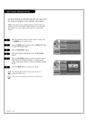
...in the selected Tuning Band. *Note: Tuning Band must be set before doing the channel search. Auto Program finds channels being received by the TV's analog and digital tuners. Auto Program (Channel Search) Use Auto Program to automatically find and store all available channels, a display appears briefly ...showing the number of the channels available in hand, press the POWER key to turn the TV on. 2 Press the MENU button and then use the ADJ D / E button to select the Channel menu. 3 Press the OK (Enter) button. 4...
...in the selected Tuning Band. *Note: Tuning Band must be set before doing the channel search. Auto Program finds channels being received by the TV's analog and digital tuners. Auto Program (Channel Search) Use Auto Program to automatically find and store all available channels, a display appears briefly ...showing the number of the channels available in hand, press the POWER key to turn the TV on. 2 Press the MENU button and then use the ADJ D / E button to select the Channel menu. 3 Press the OK (Enter) button. 4...

Owner's Manual
Page 22
... Up/Down Left/Right ADJ arrow buttons to navigate the labels menu. 4 When the label is highlighted you want for the channel shown in the TV's memory.
... Up/Down Left/Right ADJ arrow buttons to navigate the labels menu. 4 When the label is highlighted you want for the channel shown in the TV's memory.


