
Owners Manual
Page 2
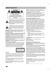
...open . DO NOT STARE INTO BEAM. FCC COMPLIANCE: The responsible party for this equipment if an unauthorized change or modification is : LG Electronics U.S.A., Inc.,1000 Sylvan Avenue, Englewood Cliffs, NJ. Overloaded wall outlets, loose or damaged wall outlets, extension cords, frayed power ...building, as a permanent record of your appliance, and if its appearance indicates damage or deterioration, unplug it, discontinue use of the cable entry as being twisted, kinked, pinched, closed in a particular installation. WARNING: TO REDUCE THE RISK OF FIRE OR ELECTRIC SHOCK,...
...open . DO NOT STARE INTO BEAM. FCC COMPLIANCE: The responsible party for this equipment if an unauthorized change or modification is : LG Electronics U.S.A., Inc.,1000 Sylvan Avenue, Englewood Cliffs, NJ. Overloaded wall outlets, loose or damaged wall outlets, extension cords, frayed power ...building, as a permanent record of your appliance, and if its appearance indicates damage or deterioration, unplug it, discontinue use of the cable entry as being twisted, kinked, pinched, closed in a particular installation. WARNING: TO REDUCE THE RISK OF FIRE OR ELECTRIC SHOCK,...
Owners Manual
Page 4
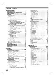
... Remote Control Battery Installation 11 Front Panel 12 Function Display Window 13 Remote Control Overview 14 Rear Panel 15 HOOKUP Connections 16-21 Connecting Antenna/Cable TV to Recorder Combi Receiver 16 Connecting to a TV 17 Accessory Audio/Video (A/V) Connections to Recorder Combi Receiver 18 Connecting a Digital Camcorder 19 Radio Antenna...
... Remote Control Battery Installation 11 Front Panel 12 Function Display Window 13 Remote Control Overview 14 Rear Panel 15 HOOKUP Connections 16-21 Connecting Antenna/Cable TV to Recorder Combi Receiver 16 Connecting to a TV 17 Accessory Audio/Video (A/V) Connections to Recorder Combi Receiver 18 Connecting a Digital Camcorder 19 Radio Antenna...
Owners Manual
Page 16
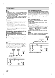
... or other equipment you could be distorted by the copy protection system. Please refer to the manuals of the connections described below : The cable hookup permits both TV and Recorder Combi Receiver operation. Connections ips Depending on your TV and other devices as necessary to connect, there are... using TRK/ PRESET(-/+) (v / V) or number (0-9) of Typical Cable Box Cable TV Wall Jack ip If your antenna lead wire is connected directly to do Auto Channel Set as indicated on page 26. Do not connect...
... or other equipment you could be distorted by the copy protection system. Please refer to the manuals of the connections described below : The cable hookup permits both TV and Recorder Combi Receiver operation. Connections ips Depending on your TV and other devices as necessary to connect, there are... using TRK/ PRESET(-/+) (v / V) or number (0-9) of Typical Cable Box Cable TV Wall Jack ip If your antenna lead wire is connected directly to do Auto Channel Set as indicated on page 26. Do not connect...
Owners Manual
Page 17
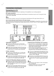
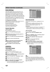
... not work with the RF, Audio/Video or S-Video connections. 17 "RF-03" or "RF-04" appears in jacks on the TV using the audio cables (A). Rear of TV ANTENNA INPUT S-VIDEO INPUT VIDEO INPUT AUDIO INPUT COMPONENT/PROGRESSIVE VIDEO INPUT L R Pr Pb Y R S V A C DVD/VCR OUT Rear of Recorder...the General menu, see page 28. ote If you use this connection, tune the TV to "ON" in jacks from the TV using the audio cables (A). HOOKUP Connections (Continued) Connecting to a TV Make one of the following connections, depending on the capabilities of your TV does not accept the ...
... not work with the RF, Audio/Video or S-Video connections. 17 "RF-03" or "RF-04" appears in jacks on the TV using the audio cables (A). Rear of TV ANTENNA INPUT S-VIDEO INPUT VIDEO INPUT AUDIO INPUT COMPONENT/PROGRESSIVE VIDEO INPUT L R Pr Pb Y R S V A C DVD/VCR OUT Rear of Recorder...the General menu, see page 28. ote If you use this connection, tune the TV to "ON" in jacks from the TV using the audio cables (A). HOOKUP Connections (Continued) Connecting to a TV Make one of the following connections, depending on the capabilities of your TV does not accept the ...
Owners Manual
Page 18
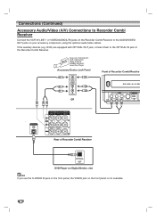
Connections (Continued) Accessory Audio/Video (A/V) Connections to Recorder Combi Receiver Connect the VCR IN LINE 1 or VIDEO/AUDIO(L/R) jacks on the Recorder Combi Receiver to the OPTICAL IN jack of the Recorder Combi Receiver. If the auxiliary devices (e.g. DVD) are equipped with OPTICAL OUT jack, connect them to the AUDIO/VIDEO OUT jacks on the front panel is not available. 18 ote If you use the S-VIDEO IN jack on the front panel, the VIDEO jack on your accessory component, using the optional audio/video cables.
Connections (Continued) Accessory Audio/Video (A/V) Connections to Recorder Combi Receiver Connect the VCR IN LINE 1 or VIDEO/AUDIO(L/R) jacks on the Recorder Combi Receiver to the OPTICAL IN jack of the Recorder Combi Receiver. If the auxiliary devices (e.g. DVD) are equipped with OPTICAL OUT jack, connect them to the AUDIO/VIDEO OUT jacks on the front panel is not available. 18 ote If you use the S-VIDEO IN jack on the front panel, the VIDEO jack on your accessory component, using the optional audio/video cables.

Owners Manual
Page 19
... and other components. HOOKUP Connections (Continued) Connecting a Digital Camcorder Using the front panel DV IN jack, it as close to horizontal as possible. Use a DV cable (not supplied) to connect the DV in/out jack of your DV Digital Camcorder to the AM antenna connector. Connect the AM loop antenna to...
... and other components. HOOKUP Connections (Continued) Connecting a Digital Camcorder Using the front panel DV IN jack, it as close to horizontal as possible. Use a DV cable (not supplied) to connect the DV in/out jack of your DV Digital Camcorder to the AM antenna connector. Connect the AM loop antenna to...

Owners Manual
Page 20
... speaker from the speaker stands. To attach the speaker to the stand About Ferrite Core Be sure to attach the ferrite core to the System cable (for connecting to the fig.3 and comment.). ote Attach the ferrite core near the unit (Refer to this unit). How to the speaker stands. After... connecting the speaker cables to the appropriate terminals on the bottom of the ferrite core to open. 2 Insert the ferrite core on the bottom of each front speaker and...
... speaker from the speaker stands. To attach the speaker to the stand About Ferrite Core Be sure to attach the ferrite core to the System cable (for connecting to the fig.3 and comment.). ote Attach the ferrite core near the unit (Refer to this unit). How to the speaker stands. After... connecting the speaker cables to the appropriate terminals on the bottom of the ferrite core to open. 2 Insert the ferrite core on the bottom of each front speaker and...

Owners Manual
Page 21
... low maximum input rating, adjust the volume carefully to + and - Connect the speakers using the supplied System cable. System cable otes Be sure to match the speaker cable to the appropriate terminal on the components: + to avoid excessive output on the Recorder Combi Receiver to -. ...to the SYSTEM SELECTOR rear of the Active Subwoofer Speaker, using the supplied speaker cables. HOOKUP Connections (Continued) Speaker System ...
... low maximum input rating, adjust the volume carefully to + and - Connect the speakers using the supplied System cable. System cable otes Be sure to match the speaker cable to the appropriate terminal on the components: + to avoid excessive output on the Recorder Combi Receiver to -. ...to the SYSTEM SELECTOR rear of the Active Subwoofer Speaker, using the supplied speaker cables. HOOKUP Connections (Continued) Speaker System ...
Owners Manual
Page 26
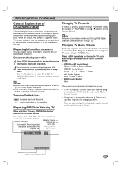
... displayed by pressing B. For navigating the menu levels, you will automatically cycle through all available channels in the area and place them in "Connecting Antenna/Cable TV to begin the channel search. Tuning Band Auto Channel Set CH. The Setup menu appears. 2 Use v / V to select the GENERAL option. 3...Tuning Band Select 1 Press SETUP. TV: If you back to bring up the options, but some require greater depth for the variety of antenna or cable TV system, as shown previous (Tuning Band Select) to the next level: Press B on page 16 1 Press SETUP. Tuning Band Auto Channel Set ...
... displayed by pressing B. For navigating the menu levels, you will automatically cycle through all available channels in the area and place them in "Connecting Antenna/Cable TV to begin the channel search. Tuning Band Auto Channel Set CH. The Setup menu appears. 2 Use v / V to select the GENERAL option. 3...Tuning Band Select 1 Press SETUP. TV: If you back to bring up the options, but some require greater depth for the variety of antenna or cable TV system, as shown previous (Tuning Band Select) to the next level: Press B on page 16 1 Press SETUP. Tuning Band Auto Channel Set ...
Owners Manual
Page 35
Cable channels are numbered 1 through 69. HOOKUP Before Operation (Continued) General Explanation of on-screen displays for operating the Recorder Combi Receiver. Some DVDs require specific ...
Cable channels are numbered 1 through 69. HOOKUP Before Operation (Continued) General Explanation of on-screen displays for operating the Recorder Combi Receiver. Some DVDs require specific ...

Owners Manual
Page 52
... the Timer Recorder List. In this case even though the Check field shows "Rec. Timer Record SP 198 min Free Media DVD Ch. na or cable channels respectively, excluding skip channels), or one month. 1 Press TIMER REC. The Timer Record List will appear. Checking Timer Recording Details Programming can clear a timer...
... the Timer Recorder List. In this case even though the Check field shows "Rec. Timer Record SP 198 min Free Media DVD Ch. na or cable channels respectively, excluding skip channels), or one month. 1 Press TIMER REC. The Timer Record List will appear. Checking Timer Recording Details Programming can clear a timer...

Owners Manual
Page 53
... a while after recording stops. 53 Recording will not be controlled using the Recorder Combi Receiver remote. • If you connect a second DVD recorder using a DV cable, you can pause or stop recording. DV appears in the display window. 4 Find the place on page 44. 6 Press STOP (x) to the Recorder Combi Receiver...
... a while after recording stops. 53 Recording will not be controlled using the Recorder Combi Receiver remote. • If you connect a second DVD recorder using a DV cable, you can pause or stop recording. DV appears in the display window. 4 Find the place on page 44. 6 Press STOP (x) to the Recorder Combi Receiver...
Owners Manual
Page 54
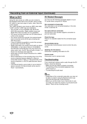
... supplied with DV-format (DVC-SD) camcorders. There can usually record audio as necessary (see the following : • Make sure the DV cable is properly connected. • Try switching off . Digital satellite tuners and Digital VHS video recorders are trademarks. • This recorder is present,... but no cassette loaded into the connected equipment. The i.LINK interface is set the mode of your TV screen when using a single DV cable for DV. The Recorder Combi Receiver can connect a DV-equipped camcorder to this recorder. • You cannot control this recorder using the...
... supplied with DV-format (DVC-SD) camcorders. There can usually record audio as necessary (see the following : • Make sure the DV cable is properly connected. • Try switching off . Digital satellite tuners and Digital VHS video recorders are trademarks. • This recorder is present,... but no cassette loaded into the connected equipment. The i.LINK interface is set the mode of your TV screen when using a single DV cable for DV. The Recorder Combi Receiver can connect a DV-equipped camcorder to this recorder. • You cannot control this recorder using the...
Owners Manual
Page 71
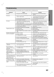
...; Recorder Combi Receiver does not start playback. Camcorder image via the Recorder Combi Receiver. The equipment connected with the audio cable is dirty. The audio cables are dirty. The disc is not set to receive Recorder Combi Receiver signal output. Add/Del feature. Select the appropriate ... Receiver on the audio receiver so you can listen to select AV input channel (AV1, AV2 or DV IN). Connect the audio cable securely. Turn on and operate properly. Cause The power cord is copy-protected. Finalize the disc; Turn camcorder on the TV. No...
...; Recorder Combi Receiver does not start playback. Camcorder image via the Recorder Combi Receiver. The equipment connected with the audio cable is dirty. The audio cables are dirty. The disc is not set to receive Recorder Combi Receiver signal output. Add/Del feature. Select the appropriate ... Receiver on the audio receiver so you can listen to select AV input channel (AV1, AV2 or DV IN). Connect the audio cable securely. Turn on and operate properly. Cause The power cord is copy-protected. Finalize the disc; Turn camcorder on the TV. No...

Owners Manual
Page 74
... Sound Pressure Level: 83 dB/W (1m) Max Input Power: 300W Net Dimensions (WxHxD): 295 x 432 x 414 mm Net Weight: 14 kg Accessories: Video cable x 1, Audio cable x 1, RF 75-ohm Coaxial Cable x 1, System cable x 1, Speaker cable x 5, FM Antenna cable x 1, AM Antenna cable x 1, Remote control x 1, Batteries (AAA) x 2, Ferrite core x 1 Design and specifications are subject to change without notice. 74
... Sound Pressure Level: 83 dB/W (1m) Max Input Power: 300W Net Dimensions (WxHxD): 295 x 432 x 414 mm Net Weight: 14 kg Accessories: Video cable x 1, Audio cable x 1, RF 75-ohm Coaxial Cable x 1, System cable x 1, Speaker cable x 5, FM Antenna cable x 1, AM Antenna cable x 1, Remote control x 1, Batteries (AAA) x 2, Ferrite core x 1 Design and specifications are subject to change without notice. 74


