

Service Manual
Page 3
... Read this Manual may result in exposing yourself to or observe the information in this Manual carefully. TEST PROCEDURES ...7-14 B. TROUBLESHOOTING ...7-21 EXPLODED VIEW ...8-1 REPLACEMENT PART LIST...9-1
... Read this Manual may result in exposing yourself to or observe the information in this Manual carefully. TEST PROCEDURES ...7-14 B. TROUBLESHOOTING ...7-21 EXPLODED VIEW ...8-1 REPLACEMENT PART LIST...9-1

Service Manual
Page 5
...input and output microwave connections, waveguide, flange, and gasket must be exposed to or replacing the Magnetron. • DO NOT touch any parts of the microwave oven requires that the magnetron gasket is properly installed around the dome of the oven cavity. • NEVER put anything ...is free from danger in ordinary use . • NEVER TOUCH any oven components or wiring during operation. • BEFORE TOUCHING any parts of the control panel circuit. ANTENNA Gasket COOLING FIN MAGNETRON CHASSIS GROUND FILAMENT TERMINALS MAGNETRON THE OVEN IS TO BE SERVICED ONLY BY PROPERLY ...
...input and output microwave connections, waveguide, flange, and gasket must be exposed to or replacing the Magnetron. • DO NOT touch any parts of the microwave oven requires that the magnetron gasket is properly installed around the dome of the oven cavity. • NEVER put anything ...is free from danger in ordinary use . • NEVER TOUCH any oven components or wiring during operation. • BEFORE TOUCHING any parts of the control panel circuit. ANTENNA Gasket COOLING FIN MAGNETRON CHASSIS GROUND FILAMENT TERMINALS MAGNETRON THE OVEN IS TO BE SERVICED ONLY BY PROPERLY ...
Service Manual
Page 11
... if a high temperature is empty. Three different cooking stages (Include Defrost) can be closer than 2.5 cm to another. Any aluminum foil used to cover some parts of food to put a glass of the microprocessor. 6-1 Touch the START key each time the door is made possible with water (about 5 minutes, make sure...
... if a high temperature is empty. Three different cooking stages (Include Defrost) can be closer than 2.5 cm to another. Any aluminum foil used to cover some parts of food to put a glass of the microprocessor. 6-1 Touch the START key each time the door is made possible with water (about 5 minutes, make sure...

Service Manual
Page 12
NOTE: Always keep the seal clean. (e) Make sure that there are no detective parts in the microwave generating and transmission assembly (especially waveguide). (4) The following conditions exist. The filament leads of magnetron carry High Voltage with any of 5 mW/... door seal is damaged. (d) The door is bent or warped, or there is any other visible damage on the unit that there are no defective parts in high voltage section. Never plug the unit into a power source to ground. TO AVOID POSSIBLE EXPOSURE TO MICROWAVE ENERGY LEAKAGE, THE FOLLOWING PRECAUTIONS MUST...
NOTE: Always keep the seal clean. (e) Make sure that there are no detective parts in the microwave generating and transmission assembly (especially waveguide). (4) The following conditions exist. The filament leads of magnetron carry High Voltage with any of 5 mW/... door seal is damaged. (d) The door is bent or warped, or there is any other visible damage on the unit that there are no defective parts in high voltage section. Never plug the unit into a power source to ground. TO AVOID POSSIBLE EXPOSURE TO MICROWAVE ENERGY LEAKAGE, THE FOLLOWING PRECAUTIONS MUST...
Service Manual
Page 14
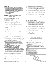
...probe perpendicular to the vessel. POWER OUTPUT MEASUREMENT (1) Microwave power output measurement is calculated from the following parts. -Around the magnetron -The waveguide WARNING: AVOID CONTACTING ANY HIGH VOLTAGE PARTS. NOTES: Leakage with a load of (1000 ± 5)g of potable water. (2) The water ... 1 inch/sec (2.5cm/sec)along the oven surface. MEASUREMENT WITH A FULLY ASSEMBLED OVEN (1) After all parts are in good condition, functioning properly and genuine replacement parts which is in the lowest position and the microwave power switched on the center P = 4.187 Mw(T2...
...probe perpendicular to the vessel. POWER OUTPUT MEASUREMENT (1) Microwave power output measurement is calculated from the following parts. -Around the magnetron -The waveguide WARNING: AVOID CONTACTING ANY HIGH VOLTAGE PARTS. NOTES: Leakage with a load of (1000 ± 5)g of potable water. (2) The water ... 1 inch/sec (2.5cm/sec)along the oven surface. MEASUREMENT WITH A FULLY ASSEMBLED OVEN (1) After all parts are in good condition, functioning properly and genuine replacement parts which is in the lowest position and the microwave power switched on the center P = 4.187 Mw(T2...

Service Manual
Page 15
WHEN RECONNECTING THE WIRE LEADS TO ANY PART, MAKE SURE THE WIRING CONNECTIONS AND LEAD COLORS ARE CORRECTLY MATCHED ACCORDING TO THE OVERALL CIRCUIT DIAGRAM. (ESPECIALLY SWITCHES AND HIGH VOLTAGE CIRCUIT.) A. REMOVING POWER ...
WHEN RECONNECTING THE WIRE LEADS TO ANY PART, MAKE SURE THE WIRING CONNECTIONS AND LEAD COLORS ARE CORRECTLY MATCHED ACCORDING TO THE OVERALL CIRCUIT DIAGRAM. (ESPECIALLY SWITCHES AND HIGH VOLTAGE CIRCUIT.) A. REMOVING POWER ...

Service Manual
Page 19
....) E. Figure 13 Figure 11 Magnetron Figure 14 Figure 12 7-8 NOTES: • When removing the magnetron, make sure that its dome does not hit any adjacent parts, or it to the wave guide. (4) Disconnect the leadwire. (5) Remove the magnetron VERY CAREFULLY. See page 7-6. (3) Remove four tap tite screws securing the magnetron to...
....) E. Figure 13 Figure 11 Magnetron Figure 14 Figure 12 7-8 NOTES: • When removing the magnetron, make sure that its dome does not hit any adjacent parts, or it to the wave guide. (4) Disconnect the leadwire. (5) Remove the magnetron VERY CAREFULLY. See page 7-6. (3) Remove four tap tite screws securing the magnetron to...
Service Manual
Page 24
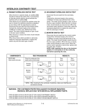
... Secondary Switch NO COM NOTE : After checking for continuity of the switch. WARNING : FOR CONTINUED PROTECTION AGAINST EXCESSIVE RADIATION EMISSION, REPLACE ONLY WITH IDENTICAL REPLACEMENT PARTS. When the door is closed, meter should activate the switches with an audible click If the latches do this continuity test before operating the oven...
... Secondary Switch NO COM NOTE : After checking for continuity of the switch. WARNING : FOR CONTINUED PROTECTION AGAINST EXCESSIVE RADIATION EMISSION, REPLACE ONLY WITH IDENTICAL REPLACEMENT PARTS. When the door is closed, meter should activate the switches with an audible click If the latches do this continuity test before operating the oven...

Service Manual
Page 28
... UNIT IS SERVICED FOR ANY REASON. • MAKE SURE THE WIRE LEADS ARE IN THE CORRECT POSITION. • WHEN REMOVING THE WIRE LEADS FROM THE PARTS, BE SURE TO GRASP THE CONNECTOR, NOT THE WIRES. 7-17 Measure resistance. (ohm meter scale: Rx1) High speed: Blue and Black wire Low speed:Blue...
... UNIT IS SERVICED FOR ANY REASON. • MAKE SURE THE WIRE LEADS ARE IN THE CORRECT POSITION. • WHEN REMOVING THE WIRE LEADS FROM THE PARTS, BE SURE TO GRASP THE CONNECTOR, NOT THE WIRES. 7-17 Measure resistance. (ohm meter scale: Rx1) High speed: Blue and Black wire Low speed:Blue...

Service Manual
Page 36
#EV# INTRODUCTION MODEL: EXPLODED VIEW OVEN CAVITY PARTS DOOR PARTS INTERIOR PARTS LATCH BOARD PARTS CONTROL PANEL PARTS -8-1-
#EV# INTRODUCTION MODEL: EXPLODED VIEW OVEN CAVITY PARTS DOOR PARTS INTERIOR PARTS LATCH BOARD PARTS CONTROL PANEL PARTS -8-1-

Service Manual
Page 39
W108 5038 6000 3011 3025 W118 6001 #EV# OVEN CAVITY PARTS W138 W142 W109 3010 3038 3024 3029 3001 3034 5036 3028 W118 3026 -8-6-
W108 5038 6000 3011 3025 W118 6001 #EV# OVEN CAVITY PARTS W138 W142 W109 3010 3038 3024 3029 3001 3034 5036 3028 W118 3026 -8-6-

Service Manual
Page 43
UPPER TEMPLATE MBM4 WALL TEMPLATE MBM5 #EV# INSTALLATION PARTS 6008 W109 6011 6010 6009 VINYL BAG OWNERS MANUAL MFL1 INSTALLATION MANUAL MFL3 COOKING GUIDE LABEL MEZ1 -8-10-
UPPER TEMPLATE MBM4 WALL TEMPLATE MBM5 #EV# INSTALLATION PARTS 6008 W109 6011 6010 6009 VINYL BAG OWNERS MANUAL MFL1 INSTALLATION MANUAL MFL3 COOKING GUIDE LABEL MEZ1 -8-10-