Owner's Manual (English)
Page 2
... display on the product screen. On Safety Use only the power cord supplied with your dealer. The power supply cord is faulty in your home, consult with the unit. Do not drop an object on the display. There are no user serviceable components inside , even when the power is easily accessible after installation. To Prevent Fire or Hazards: Always turn the display OFF if you use another power cord, make...
... display on the product screen. On Safety Use only the power cord supplied with your dealer. The power supply cord is faulty in your home, consult with the unit. Do not drop an object on the display. There are no user serviceable components inside , even when the power is easily accessible after installation. To Prevent Fire or Hazards: Always turn the display OFF if you use another power cord, make...
Owner's Manual (English)
Page 3
...on the screen. Main power breaker is the power cord and this breaking device must be located at a location where it in accordance to damage. Do not dispose of your LCD display. Cover the openings with anything to rest upon or roll over a radiator or heat source. Disposal... the Active Matrix LCD with cloth or other material. Do not press the LCD screen with general household waste. When shipping the unit to obtain the best image quality for a long time as Red, Green or Blue spots on the display performance. Do not use the recommended resolution to another location...
...on the screen. Main power breaker is the power cord and this breaking device must be located at a location where it in accordance to damage. Do not dispose of your LCD display. Cover the openings with anything to rest upon or roll over a radiator or heat source. Disposal... the Active Matrix LCD with cloth or other material. Do not press the LCD screen with general household waste. When shipping the unit to obtain the best image quality for a long time as Red, Green or Blue spots on the display performance. Do not use the recommended resolution to another location...
Owner's Manual (English)
Page 4
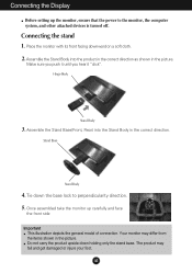
... from the items shown in the picture. Connecting the stand 1. Assemble the Stand Body into the Stand Body in the picture. Do not carry the product upside down the base lock to the monitor, the computer system, and other attached devices is turned off. Your monitor may fall and get damaged or injure your foot. Connecting the Display Before setting up carefully and face the...
... from the items shown in the picture. Connecting the stand 1. Assemble the Stand Body into the Stand Body in the picture. Do not carry the product upside down the base lock to the monitor, the computer system, and other attached devices is turned off. Your monitor may fall and get damaged or injure your foot. Connecting the Display Before setting up carefully and face the...
Owner's Manual (English)
Page 5
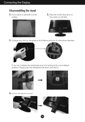
Change your lock on the cushion or soft cloth. 3. If you can't release the stand base even the locking knob is at a release position, Please push the indicated knob down on the product as it follows and turn it . 4. A4 Pull out the stand to remove. Place the monitor face down and retry it in the arrow direction. Put a cushion or soft cloth on a flat surface. 2. Connecting the Display Disassembling the stand 1.
Change your lock on the cushion or soft cloth. 3. If you can't release the stand base even the locking knob is at a release position, Please push the indicated knob down on the product as it follows and turn it . 4. A4 Pull out the stand to remove. Place the monitor face down and retry it in the arrow direction. Put a cushion or soft cloth on a flat surface. 2. Connecting the Display Disassembling the stand 1.
Owner's Manual (English)
Page 6
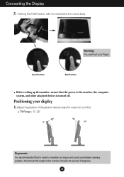
... tilt angle of the monitor should not exceed 5 degrees. Positioning your finger. Adjust the position of the panel in order to the monitor, the computer system, and other attached devices is turned off. A5 Warning: You can hurt your display 1. Good Position Bad Position Before setting up the monitor, ensure that in various ways for maximum comfort. Connecting the Display 5. Pushing the PUSH button, take the stand base...
... tilt angle of the monitor should not exceed 5 degrees. Positioning your finger. Adjust the position of the panel in order to the monitor, the computer system, and other attached devices is turned off. A5 Warning: You can hurt your display 1. Good Position Bad Position Before setting up the monitor, ensure that in various ways for maximum comfort. Connecting the Display 5. Pushing the PUSH button, take the stand base...
Owner's Manual (English)
Page 7
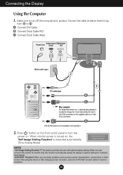
...Only Analog Mode) NOTE ' Self Image Setting Function'? This function provides the user with optimal display settings.When the user connects the monitor for individual input signals. 'AUTO/SET' Function? A6 When you encounter problems such as below sketch map form 1 to turn the power on , the 'Self Image Setting Function' is turned on . A Connect DVI Cable B Connect Dsub Cable (PC) C Connect Dsub Cable (Mac) Power Cord Analog signal Digital signal D-sub DVI PUSH Wall-outlet type PC PC-outlet type PC B MAC c Mac adapter For Apple Macintosh use, a separate plug adapter is...
...Only Analog Mode) NOTE ' Self Image Setting Function'? This function provides the user with optimal display settings.When the user connects the monitor for individual input signals. 'AUTO/SET' Function? A6 When you encounter problems such as below sketch map form 1 to turn the power on , the 'Self Image Setting Function' is turned on . A Connect DVI Cable B Connect Dsub Cable (PC) C Connect Dsub Cable (Mac) Power Cord Analog signal Digital signal D-sub DVI PUSH Wall-outlet type PC PC-outlet type PC B MAC c Mac adapter For Apple Macintosh use, a separate plug adapter is...
Owner's Manual (English)
Page 8
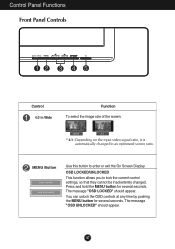
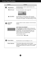
... the MENU button for several seconds. The message "OSD UNLOCKED" should appear. A7 MENU Button Use this button to an optimized screen ratio. Press and hold the MENU button for several seconds. The message "OSD LOCKED" should appear. OSD LOCKED/UNLOCKED This function allows you to lock the current control settings, so that they cannot be inadvertently changed to enter or exit the On Screen Display. Control Panel Functions Front Panel Controls Control 4:3 in Wide Function To select the image size...
... the MENU button for several seconds. The message "OSD UNLOCKED" should appear. A7 MENU Button Use this button to an optimized screen ratio. Press and hold the MENU button for several seconds. The message "OSD LOCKED" should appear. OSD LOCKED/UNLOCKED This function allows you to lock the current control settings, so that they cannot be inadvertently changed to enter or exit the On Screen Display. Control Panel Functions Front Panel Controls Control 4:3 in Wide Function To select the image size...
Owner's Manual (English)
Page 9
... the display. AUTO/SET Button Use this button to turn the display on or off. This feature is D-Sub. Use this indicator color changes to amber. Control Panel Functions Control Buttons Function Use these buttons to select or adjust functions in the On Screen Display. For more information, refer to the ideal settings for the current screen resolution size (display mode). If the display is - 21.6 inch monitor : 1680 x 1050 Power Button Power Indicator Use this button to make D-Sub or DVI connector active. A8 AUTO IMAGE ADJUSTMENT When adjusting your display image to...
... the display. AUTO/SET Button Use this button to turn the display on or off. This feature is D-Sub. Use this indicator color changes to amber. Control Panel Functions Control Buttons Function Use these buttons to select or adjust functions in the On Screen Display. For more information, refer to the ideal settings for the current screen resolution size (display mode). If the display is - 21.6 inch monitor : 1680 x 1050 Power Button Power Indicator Use this button to make D-Sub or DVI connector active. A8 AUTO IMAGE ADJUSTMENT When adjusting your display image to...
Owner's Manual (English)
Page 10
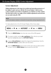
... the On Screen Display Control system. A short example is an outline of the display is quick and easy with the use the or Buttons. NOTE Allow the display to select another function. Use the AUTO/SET Button to select other sub-menu items. Push the MENU Button once to return to the main menu to stabilize for at least 30 minutes before making image adjustments. On Screen Display (OSD) Control Adjustment Screen Adjustment Making adjustments to the image size, position and...
... the On Screen Display Control system. A short example is an outline of the display is quick and easy with the use the or Buttons. NOTE Allow the display to select another function. Use the AUTO/SET Button to select other sub-menu items. Push the MENU Button once to return to the main menu to stabilize for at least 30 minutes before making image adjustments. On Screen Display (OSD) Control Adjustment Screen Adjustment Making adjustments to the image size, position and...
Owner's Manual (English)
Page 11
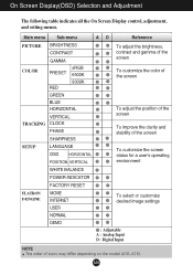
...-menu A D Reference PICTURE BRIGHTNESS CONTRAST GAMMA To adjust the brightness, contrast and gamma of the screen COLOR PRESET RED sRGB 6500K 9300K To customize the color of the screen GREEN BLUE HORIZONTAL VERTICAL TRACKING CLOCK PHASE SHARPNESS To adjust the position of the screen To improve the clarity and stability of the screen SETUP LANGUAGE OSD HORIZONTAL POSITION VERTICAL To customize the screen status for a user's operating environment WHITE BALANCE POWER INDICATOR FACTORY RESET FLATRON F-ENGINE MOVIE INTERNET USER To select or customize desired image settings...
...-menu A D Reference PICTURE BRIGHTNESS CONTRAST GAMMA To adjust the brightness, contrast and gamma of the screen COLOR PRESET RED sRGB 6500K 9300K To customize the color of the screen GREEN BLUE HORIZONTAL VERTICAL TRACKING CLOCK PHASE SHARPNESS To adjust the position of the screen To improve the clarity and stability of the screen SETUP LANGUAGE OSD HORIZONTAL POSITION VERTICAL To customize the screen status for a user's operating environment WHITE BALANCE POWER INDICATOR FACTORY RESET FLATRON F-ENGINE MOVIE INTERNET USER To select or customize desired image settings...
Owner's Manual (English)
Page 12
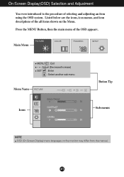
On Screen Display(OSD) Selection and Adjustment You were introduced to the procedure of the OSD appears. Main Menu MENU : Exit - + : Adjust (Decrease/Increase) SET : Enter : Select another sub-menu Menu Name Button Tip Icons Sub-menus NOTE OSD (On Screen Display) menu languages on the Menu. A11 Press the MENU Button, then the main menu of selecting and adjusting an item using the OSD system. Listed below are the icons, icon names, and icon descriptions of the all items shown on the monitor may differ from the manual.
On Screen Display(OSD) Selection and Adjustment You were introduced to the procedure of the OSD appears. Main Menu MENU : Exit - + : Adjust (Decrease/Increase) SET : Enter : Select another sub-menu Menu Name Button Tip Icons Sub-menus NOTE OSD (On Screen Display) menu languages on the Menu. A11 Press the MENU Button, then the main menu of selecting and adjusting an item using the OSD system. Listed below are the icons, icon names, and icon descriptions of the all items shown on the monitor may differ from the manual.
Owner's Manual (English)
Page 13
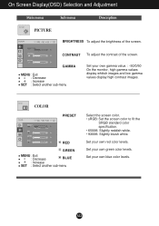
... green color levels. On Screen Display(OSD) Selection and Adjustment Main menu PICTURE PICTURE Sub menu Description BRIGHTNESS To adjust the brightness of the screen. A12 Set your own red color levels. COLOR COLOR PRESET RED GREEN MENU : Exit : Decrease BLUE : Increase SET : Select another sub-menu Set your own blue color levels. CONTRAST To adjust the contrast of the screen. Set your own gamma value. : -50/0/50 On the monitor, high gamma values display whitish images and low gamma values display high contrast images. GAMMA MENU : Exit : Decrease : Increase SET...
... green color levels. On Screen Display(OSD) Selection and Adjustment Main menu PICTURE PICTURE Sub menu Description BRIGHTNESS To adjust the brightness of the screen. A12 Set your own red color levels. COLOR COLOR PRESET RED GREEN MENU : Exit : Decrease BLUE : Increase SET : Select another sub-menu Set your own blue color levels. CONTRAST To adjust the contrast of the screen. Set your own gamma value. : -50/0/50 On the monitor, high gamma values display whitish images and low gamma values display high contrast images. GAMMA MENU : Exit : Decrease : Increase SET...
Owner's Manual (English)
Page 14
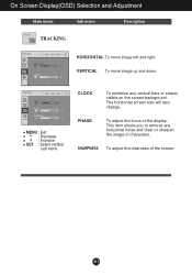
The horizontal screen size will also change. SHARPNESS To adjust the clearness of the display. On Screen Display(OSD) Selection and Adjustment Main menu Sub menu Description TRACKING TRACKING HORIZONTAL To move image up and down. PHASE To adjust the focus of the screen. VERTICAL To move image left and right. A13 MENU : Exit : Decrease : Increase SET : Select another sub-menu CLOCK To minimize any horizontal noise and clear or sharpen the image of characters. This item allows you to remove any vertical bars or stripes visible on the screen background.
The horizontal screen size will also change. SHARPNESS To adjust the clearness of the display. On Screen Display(OSD) Selection and Adjustment Main menu Sub menu Description TRACKING TRACKING HORIZONTAL To move image up and down. PHASE To adjust the focus of the screen. VERTICAL To move image left and right. A13 MENU : Exit : Decrease : Increase SET : Select another sub-menu CLOCK To minimize any horizontal noise and clear or sharpen the image of characters. This item allows you to remove any vertical bars or stripes visible on the screen background.
Owner's Manual (English)
Page 15
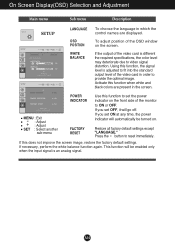
... the video card is different the required specifications, the color level may deteriorate due to reset immediately. MENU : Exit : Adjust : Adjust SET : Select another sub-menu POWER INDICATOR FACTORY RESET Use this function when white and black colors are present in which the SETUP SETUP control names are displayed. If this function, the signal level is an analog signal. This function will go off. OSD POSITION To adjust position of the OSD window on the front side of the video card in...
... the video card is different the required specifications, the color level may deteriorate due to reset immediately. MENU : Exit : Adjust : Adjust SET : Select another sub-menu POWER INDICATOR FACTORY RESET Use this function when white and black colors are present in which the SETUP SETUP control names are displayed. If this function, the signal level is an analog signal. This function will go off. OSD POSITION To adjust position of the OSD window on the front side of the video card in...
Owner's Manual (English)
Page 16
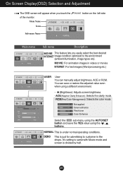
... best desired INTERNET image condition optimized to customer in videos or movies INTERNET: For text images (Word processing etc.) USER User You can save or restore the adjusted value even when using a different environment. ... (Brightness): Adjusts screen brightness. ...ACE(Adaptive Clarity Enhancer): Selects the clarity mode. ...RCM(Real Color Management): Selects the color mode. 0 Not applied 1 Green enhance 2 Flesh tone 3 Color Enhance Select the sub-menu using the AUTO/SET button and save the YES value using the , buttons...
... best desired INTERNET image condition optimized to customer in videos or movies INTERNET: For text images (Word processing etc.) USER User You can save or restore the adjusted value even when using a different environment. ... (Brightness): Adjusts screen brightness. ...ACE(Adaptive Clarity Enhancer): Selects the clarity mode. ...RCM(Real Color Management): Selects the color mode. 0 Not applied 1 Green enhance 2 Flesh tone 3 Color Enhance Select the sub-menu using the AUTO/SET button and save the YES value using the , buttons...
Owner's Manual (English)
Page 17
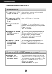
... see a "CHECK SIGNAL CABLE" message on the screen? • This message appears when the signal cable between your PC and your display is not connected. You can secure the current control settings, so that they cannot be inadvertently changed. See the 'Specifications' section of the display. Check the signal cable and try moving the mouse or pressing any time by pushing the MENU button for service. power indicator blue or green? ●...
... see a "CHECK SIGNAL CABLE" message on the screen? • This message appears when the signal cable between your PC and your display is not connected. You can secure the current control settings, so that they cannot be inadvertently changed. See the 'Specifications' section of the display. Check the signal cable and try moving the mouse or pressing any time by pushing the MENU button for service. power indicator blue or green? ●...
Owner's Manual (English)
Page 18
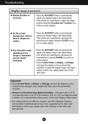
..., adjust the image position using the PHASE icon in the on screen display. ● Any horizontal noise appearing in the on screen display. ● On the screen background, vertical bars or stripes are not clearly portrayed. • Press the AUTO/SET button to automatically adjust your display image to the ideal setting. Important Check Control Panel --> Display --> Settings and see if the frequency or the resolution were changed. Troubleshooting Display image is incorrect ● Display Position is incorrect. • Press the AUTO/SET button...
..., adjust the image position using the PHASE icon in the on screen display. ● Any horizontal noise appearing in the on screen display. ● On the screen background, vertical bars or stripes are not clearly portrayed. • Press the AUTO/SET button to automatically adjust your display image to the ideal setting. Important Check Control Panel --> Display --> Settings and see if the frequency or the resolution were changed. Troubleshooting Display image is incorrect ● Display Position is incorrect. • Press the AUTO/SET button...
Owner's Manual (English)
Page 19
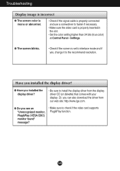
... (VESA DDC) monitor found" message? • Make sure to check if the video card supports Plug&Play function. Have you installed the display driver? ● Have you installed the display driver? • Be sure to install the display driver from our web site: http://www.lge.com. ● Do you can also download the driver from the display driver CD (or diskette) that comes with your display. A18 Troubleshooting Display image is incorrect ● The screen color...
... (VESA DDC) monitor found" message? • Make sure to check if the video card supports Plug&Play function. Have you installed the display driver? ● Have you installed the display driver? • Be sure to install the display driver from our web site: http://www.lge.com. ● Do you can also download the driver from the display driver CD (or diskette) that comes with your display. A18 Troubleshooting Display image is incorrect ● The screen color...
Owner's Manual (English)
Page 20
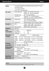
... to change without notice. Specifications W2241T Display Sync Input Video Input Resolution Plug&Play Power Consumption Dimensions & Weight Tilt Range Power Input Environmental Conditions Stand Base Power cord 21.6 inches (54.864 cm) Flat Panel Active matrix-TFT LCD, Anti-Glare coating 21.6 inches viewable 0.277*0.277 mm pixel pitch Horizontal Freq. Input Form Analog : 28 - 83 kHz (Automatic) Digital : 28 - 83 kHz (Automatic) 56 - 75 Hz (Automatic) Separate TTL, Positive/Negative SOG (Sync On Green), Digital (HDCP) Signal Input Input Form 15 pin D-Sub Connector DVI - A19 Vertical...
... to change without notice. Specifications W2241T Display Sync Input Video Input Resolution Plug&Play Power Consumption Dimensions & Weight Tilt Range Power Input Environmental Conditions Stand Base Power cord 21.6 inches (54.864 cm) Flat Panel Active matrix-TFT LCD, Anti-Glare coating 21.6 inches viewable 0.277*0.277 mm pixel pitch Horizontal Freq. Input Form Analog : 28 - 83 kHz (Automatic) Digital : 28 - 83 kHz (Automatic) 56 - 75 Hz (Automatic) Separate TTL, Positive/Negative SOG (Sync On Green), Digital (HDCP) Signal Input Input Form 15 pin D-Sub Connector DVI - A19 Vertical...
Owner's Manual (English)
Page 22
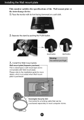
Separate the stand by pushing the PUSH button. .3 Install the Wall mount plate. Kensington Security Slot Connected to the installation guide for more details, which is provided when Wall mount plate is connectable with its front facing downward on a soft cloth. 2. A21 Place the monitor with Wall mount plate. Good Position Bad Position Warning: You can be purchased separately at most computer stores. Please refer to a locking cable that...
Separate the stand by pushing the PUSH button. .3 Install the Wall mount plate. Kensington Security Slot Connected to the installation guide for more details, which is provided when Wall mount plate is connectable with its front facing downward on a soft cloth. 2. A21 Place the monitor with Wall mount plate. Good Position Bad Position Warning: You can be purchased separately at most computer stores. Please refer to a locking cable that...


