Service Manual
Page 2
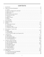
Neuro fuzzy Washing time optimization 6 2-3. Water Circulation ...7 2-9. Parts Identification ...8 4. Control Panel Features ...12-14 5-2. Load Test Mode ...22 7-3. Troubleshooting ...21-34 8-1. Pump Motor Assembly ...41 9-5. Heater Assembly ...43 9-7. Disassembly Instructions ...46-54 11. Cabinet and Control Panel Assembly 55 11-2. Water level Contorl ...6 2-4. The door can cont be Opened ...7 2-6. Explanation of Each Process 17-18 6. Test Mode ...20-34 7-1. Troubleshooting With Error ...23-29 8-4. Dispenser Assembly ...57 Y Specifications ...2-5 2. Featurs ...5 2-2....
Neuro fuzzy Washing time optimization 6 2-3. Water Circulation ...7 2-9. Parts Identification ...8 4. Control Panel Features ...12-14 5-2. Load Test Mode ...22 7-3. Troubleshooting ...21-34 8-1. Pump Motor Assembly ...41 9-5. Heater Assembly ...43 9-7. Disassembly Instructions ...46-54 11. Cabinet and Control Panel Assembly 55 11-2. Water level Contorl ...6 2-4. The door can cont be Opened ...7 2-6. Explanation of Each Process 17-18 6. Test Mode ...20-34 7-1. Troubleshooting With Error ...23-29 8-4. Dispenser Assembly ...57 Y Specifications ...2-5 2. Featurs ...5 2-2....
Service Manual
Page 3
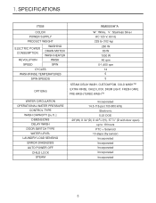
XU SPECIFICATIONS ITEM COLOR POWER SUPPLY PRODUCT WEIGHT ELECTRIC POWER CONSUMPTION REVOLUTION WASHING DRAIN MOTOR WASH HEATER WASH SPEED SPIN CYCLES WASH/RINSE TEMPERATURES SPIN SPEEDS OPTIONS WM8000H*A W : White, V : Stainless Silver AC 120 V, 60 Hz 225 lb (102 kg) 280 W 80 W 1000 W 46 rpm 0-1,400 rpm 14 5 5 STEAM, DELAY WASH, CUSTOM PGM, COLD WASH TM EXTRA RINSE, CHILD LOCK, DRUM LIGHT, FRESH CARE PRE-WASH,TURBO WASH TM WATER CIRCULATION OPERATIONAL WATER PRESSURE CONTROL TYPE WASH CAPACITY [cu.ft. ] DIMENSIONS DELAY WASH DOOR SWITCH TYPE WATER LEVEL LAUNDRY LOAD SENSING ERROR...
XU SPECIFICATIONS ITEM COLOR POWER SUPPLY PRODUCT WEIGHT ELECTRIC POWER CONSUMPTION REVOLUTION WASHING DRAIN MOTOR WASH HEATER WASH SPEED SPIN CYCLES WASH/RINSE TEMPERATURES SPIN SPEEDS OPTIONS WM8000H*A W : White, V : Stainless Silver AC 120 V, 60 Hz 225 lb (102 kg) 280 W 80 W 1000 W 46 rpm 0-1,400 rpm 14 5 5 STEAM, DELAY WASH, CUSTOM PGM, COLD WASH TM EXTRA RINSE, CHILD LOCK, DRUM LIGHT, FRESH CARE PRE-WASH,TURBO WASH TM WATER CIRCULATION OPERATIONAL WATER PRESSURE CONTROL TYPE WASH CAPACITY [cu.ft. ] DIMENSIONS DELAY WASH DOOR SWITCH TYPE WATER LEVEL LAUNDRY LOAD SENSING ERROR...
Service Manual
Page 4
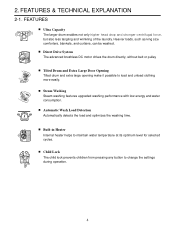
... lock prevents children from pressing any button to load and unload clothing more easily. Automatic Wash Load Detection Automatically detects the load and optimizes the washing time. FEATURES & TECHNICAL EXPLANATION 2-1. Steam Washing Steam washing features upgraded washing performance with low energy and water consumption. Direct Drive System The advanced brushless DC motor drives the drum directly, without belt or pulley Tilted Drum and Extra Large Door Opening Tilted drum and extra large opening make it possible to change the settings during operation...
... lock prevents children from pressing any button to load and unload clothing more easily. Automatic Wash Load Detection Automatically detects the load and optimizes the washing time. FEATURES & TECHNICAL EXPLANATION 2-1. Steam Washing Steam washing features upgraded washing performance with low energy and water consumption. Direct Drive System The advanced brushless DC motor drives the drum directly, without belt or pulley Tilted Drum and Extra Large Door Opening Tilted drum and extra large opening make it possible to change the settings during operation...
Service Manual
Page 5
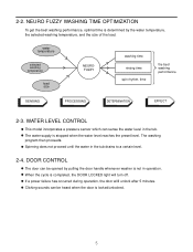
... sounds can sense the water level in the tub drains to a certain level. 2-4. NEURO FUZZY WASHING TIME OPTIMIZATION To get the best washing performance, optimal time is determined by pulling the door handle whenever washer is locked/unlocked. Spinning does not proceed until the water in the tub. When the cycle is stopped when the water level reaches the preset level. If a power failure has occurred during operation, the door wiIll unlock after 5 minutes. 2-2. water temperature selected washing temperature load size NEUROFUZZY washing time rinsing time spin...
... sounds can sense the water level in the tub drains to a certain level. 2-4. NEURO FUZZY WASHING TIME OPTIMIZATION To get the best washing performance, optimal time is determined by pulling the door handle whenever washer is locked/unlocked. Spinning does not proceed until the water in the tub. When the cycle is stopped when the water level reaches the preset level. If a power failure has occurred during operation, the door wiIll unlock after 5 minutes. 2-2. water temperature selected washing temperature load size NEUROFUZZY washing time rinsing time spin...
Service Manual
Page 6
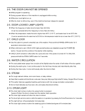
... temperature inside the tub is filled. 2-9. While door Lock lights turn off when the door is operating. To UNLOCK, press and hold RINSE+SPIN button for the first three minutes and intermittently after that. This option features upgraded washing performance with low energy and water consumption. THE DOOR CAN NOT BE OPENED While program is closed and the washer starts operation. 2-5. During a power failure or if the machine is in effect after the drum...
... temperature inside the tub is filled. 2-9. While door Lock lights turn off when the door is operating. To UNLOCK, press and hold RINSE+SPIN button for the first three minutes and intermittently after that. This option features upgraded washing performance with low energy and water consumption. THE DOOR CAN NOT BE OPENED While program is closed and the washer starts operation. 2-5. During a power failure or if the machine is in effect after the drum...
Service Manual
Page 15
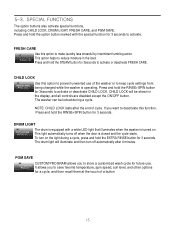
... drum is equipped with the special function for 3 seconds to store a customized wash cycle for a cycle, and then recall them at the touch of the washer or to prevent unwanted use . It allows you to save favorite temperature, spin speed, soil level, and other options for future use of a button FRESH CARE Use this option to keep cycle settings from being changed while the washer is closed and the cycle starts...
... drum is equipped with the special function for 3 seconds to store a customized wash cycle for a cycle, and then recall them at the touch of the washer or to prevent unwanted use . It allows you to save favorite temperature, spin speed, soil level, and other options for future use of a button FRESH CARE Use this option to keep cycle settings from being changed while the washer is closed and the cycle starts...
Service Manual
Page 19
SPIN SPEED SOIL LEVEL WASH/RINSE DELAY WASH 19
SPIN SPEED SOIL LEVEL WASH/RINSE DELAY WASH 19
Service Manual
Page 21
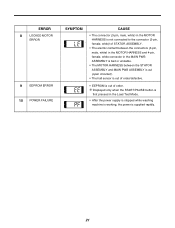
... (open circuited). • The hall sensor is out of order. Displayed only when the START/PAUSE button is first pressed in the MAIN PWB ASSEMBLY is bad or unstable. • The MOTOR HARNESS between the connectors (3-pin, male, white) in the MOTOR HARNESS and 4-pin, female, white connector in the Load Test Mode. • After the power supply is stopped while washing machine is working...
... (open circuited). • The hall sensor is out of order. Displayed only when the START/PAUSE button is first pressed in the MAIN PWB ASSEMBLY is bad or unstable. • The MOTOR HARNESS between the connectors (3-pin, male, white) in the MOTOR HARNESS and 4-pin, female, white connector in the Load Test Mode. • After the power supply is stopped while washing machine is working...

Service Manual
Page 26
DOOR OPEN ERROR START/PAUSE [Note] Installation check list 26
DOOR OPEN ERROR START/PAUSE [Note] Installation check list 26
Service Manual
Page 27
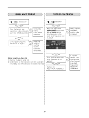
UNBALANCE ERROR OVER FLOW ERROR WASH/RINSE DELAY WASH [Note] Installation check list 27
UNBALANCE ERROR OVER FLOW ERROR WASH/RINSE DELAY WASH [Note] Installation check list 27
Service Manual
Page 29
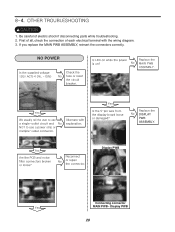
If you replace the MAIN PWB ASSEMBLY, reinsert the connectors correctly. [ 1. Be careful of each electrical terminal with the wiring diagram. 3. First of all, check the connection of electric shock if disconnecting parts while troubleshooting. 2. Display PWB Connecting connector MAIN PWB~ Display PWB 29 NO POWER DISPLAY PWB ASSEMBLY.
If you replace the MAIN PWB ASSEMBLY, reinsert the connectors correctly. [ 1. Be careful of each electrical terminal with the wiring diagram. 3. First of all, check the connection of electric shock if disconnecting parts while troubleshooting. 2. Display PWB Connecting connector MAIN PWB~ Display PWB 29 NO POWER DISPLAY PWB ASSEMBLY.

Service Manual
Page 33
LIQUID DETERGENT/SOFTENER/ BLEACH DOES NOT FLOW IN pšGžˆ›Œ™G f u– €Œš h™ŒG›ŒG—“œŽšG G›&#...;u– ›ŒGpusl{G}hs}l hzzltis€f yŒŒ™G›– uvG~h{ly z|wws€U jŒŠ’G G–•G U ABNORMAL SOUND pšG›ŒG”–›–™G‰–“›G f zŒŠœ™ŒG›Œ U €Œš pš...
LIQUID DETERGENT/SOFTENER/ BLEACH DOES NOT FLOW IN pšGžˆ›Œ™G f u– €Œš h™ŒG›ŒG—“œŽšG G›&#...;u– ›ŒGpusl{G}hs}l hzzltis€f yŒŒ™G›– uvG~h{ly z|wws€U jŒŠ’G G–•G U ABNORMAL SOUND pšG›ŒG”–›–™G‰–“›G f zŒŠœ™ŒG›Œ U €Œš pš...

Service Manual
Page 37
STATOR ASSEMBLY MOTOR Wiring diagram Circuit in either direction. Test points (Windings) WINDINGS HALL SENSOR Result (Windings) Test Points (1) to (2) (2) to (3) (3) to maximum speed in infinite steps in the MAIN PWB / Wiring Diagram MAIN PWB Ha Hb MICOM 12V 1 1 WH 2 3 2 3 RD BL 44 GY NA1NA 4 4 ...Direct Drive motor can be driven from stopped to (1) Result 5-15 Ω 5-15 Ω 5-15 Ω (3) (1) (2) 37 There are 36 poles on the stator; 12 permanent magnets spaced around the rotor. 9-3. There are no brushes to it. Unlike a more traditional brushless motor...
STATOR ASSEMBLY MOTOR Wiring diagram Circuit in either direction. Test points (Windings) WINDINGS HALL SENSOR Result (Windings) Test Points (1) to (2) (2) to (3) (3) to maximum speed in infinite steps in the MAIN PWB / Wiring Diagram MAIN PWB Ha Hb MICOM 12V 1 1 WH 2 3 2 3 RD BL 44 GY NA1NA 4 4 ...Direct Drive motor can be driven from stopped to (1) Result 5-15 Ω 5-15 Ω 5-15 Ω (3) (1) (2) 37 There are 36 poles on the stator; 12 permanent magnets spaced around the rotor. 9-3. There are no brushes to it. Unlike a more traditional brushless motor...

Service Manual
Page 38
... (Hall Sensor) - Remove rear washer panel. 3. Plug in next section. 38 DO NOT PRESS START! 6. The hall sensor determines the speed and direction of the motor. If 10 to gray. 5. Place meter leads on terminals 5 to 4, white to 15 VDC is off balance when the drum speed fluctuates. Locate Hall sensor connector on control board in power cord, close door, and press power button. Unplug power cord. 2. If not, follow testing output...
... (Hall Sensor) - Remove rear washer panel. 3. Plug in next section. 38 DO NOT PRESS START! 6. The hall sensor determines the speed and direction of the motor. If 10 to gray. 5. Place meter leads on terminals 5 to 4, white to 15 VDC is off balance when the drum speed fluctuates. Locate Hall sensor connector on control board in power cord, close door, and press power button. Unplug power cord. 2. If not, follow testing output...
Service Manual
Page 42
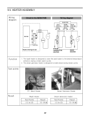
... Circuit in the MAIN PWB MICOM 12V X100 43 43 Vac Heater Wiring diagram MAIN PWB (X71) 3 4 YL 34 RD BL (X135) (X134) 3 4 BL 3 4 BK 34 34 GY BK YL BK Vac m|zl m|zl Tab Relay Heater driving circuit STEAM GENERATOR HEATER WASH HEATER m XU {ŒGžˆšGŒˆ›...
... Circuit in the MAIN PWB MICOM 12V X100 43 43 Vac Heater Wiring diagram MAIN PWB (X71) 3 4 YL 34 RD BL (X135) (X134) 3 4 BL 3 4 BK 34 34 GY BK YL BK Vac m|zl m|zl Tab Relay Heater driving circuit STEAM GENERATOR HEATER WASH HEATER m XU {ŒGžˆšGŒˆ›...

Service Manual
Page 46
PROTECT COVER 3 Disconnect the connectors. 4 Unscrew 1 screw on the back. 5 Remove the main PWB. 46 MAIN PWB ASSEMBLY 1 Disconnect the POWER connector and the pressure switch assembly. 2 Remove the protective cover.
PROTECT COVER 3 Disconnect the connectors. 4 Unscrew 1 screw on the back. 5 Remove the main PWB. 46 MAIN PWB ASSEMBLY 1 Disconnect the POWER connector and the pressure switch assembly. 2 Remove the protective cover.
Service Manual
Page 50
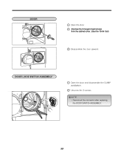
DOOR Unscrew the 6 hexgon head screws from the cabinet cover. (Use the 13mm tool) DOOR LOCK SWITCH ASSEMBLY NOTE • Reconnect the connector after replacing the DOOR SWITCH ASSEMBLY. 50
DOOR Unscrew the 6 hexgon head screws from the cabinet cover. (Use the 13mm tool) DOOR LOCK SWITCH ASSEMBLY NOTE • Reconnect the connector after replacing the DOOR SWITCH ASSEMBLY. 50

Service Manual
Page 51
... the heater, insert the heater into the heater clip on the bottom of the thermistor. 51 PUMP CIRCULATION HOSE PUMP HOSE BELLOWS HEATER THERMISTOR 1 Disassemble the cabinet cover. 2 Separate the pump hose, the bellows, the circulation hose assembly from the pump assembly. 3 Disassemble the pump assembly. 1 Disassemble the cabinet cover. 2 Separate 2 connectors from the thermistor. 3 Pull it out by holding the bracket...
... the heater, insert the heater into the heater clip on the bottom of the thermistor. 51 PUMP CIRCULATION HOSE PUMP HOSE BELLOWS HEATER THERMISTOR 1 Disassemble the cabinet cover. 2 Separate the pump hose, the bellows, the circulation hose assembly from the pump assembly. 3 Disassemble the pump assembly. 1 Disassemble the cabinet cover. 2 Separate 2 connectors from the thermistor. 3 Pull it out by holding the bracket...

Service Manual
Page 52
LAMP ASSEMBLY TOP PLATE ASSEMBLY 1 Unscrew 2 screws on the back of the top plate. 2 Pull the top plate backward and upward as shown. 3 Disconnect the connector. 52 WHEN FOREIGN OBJECT IS STUCK BETWEEN DRUM AND TUB 1 Disassemble the cabinet cover. 2 Separate the heater from the tub. 3 Remove any foreign objects (wire, coin, etc.) by inserting a long bar in the opening.
LAMP ASSEMBLY TOP PLATE ASSEMBLY 1 Unscrew 2 screws on the back of the top plate. 2 Pull the top plate backward and upward as shown. 3 Disconnect the connector. 52 WHEN FOREIGN OBJECT IS STUCK BETWEEN DRUM AND TUB 1 Disassemble the cabinet cover. 2 Separate the heater from the tub. 3 Remove any foreign objects (wire, coin, etc.) by inserting a long bar in the opening.
Service Manual
Page 54
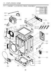
M410 A485 A455 A450 F210 A410 A140 A152 A139 A153 A150 A154 A141 A110 A111 A156 A151 A130 A134 A133 A390 A131 A310 A303 A300 A200 54 "The following parts are not illustrated" Description *Owner's Manual Loc No. G001 *Energy Label G002 *Service Manual Printed materials *Label,Circuit *Quick Start Guides G004 G005 G006 *Installation Sheet G007 *Non-Skid Pads G010 F215 F211 A102 A103 F110 A104 A105 A101 A100 A430 A201 A220 A440 A155
M410 A485 A455 A450 F210 A410 A140 A152 A139 A153 A150 A154 A141 A110 A111 A156 A151 A130 A134 A133 A390 A131 A310 A303 A300 A200 54 "The following parts are not illustrated" Description *Owner's Manual Loc No. G001 *Energy Label G002 *Service Manual Printed materials *Label,Circuit *Quick Start Guides G004 G005 G006 *Installation Sheet G007 *Non-Skid Pads G010 F215 F211 A102 A103 F110 A104 A105 A101 A100 A430 A201 A220 A440 A155


