Service Manual
Page 2
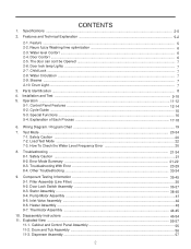
...-1. Special Functions ...16 5-4. Safety Caution ...20 7-2. Door Look Switch Assembly 36-37 9-3. Stator Assembly ...38-40 9-4. Thermistor Assembly ...44-45 10. Door lock lamp Lights ...7 2-7. Parts Identification ...8 4. Control Panel Features ...12-14 5-2. Inlet Valve Assembly ...42 9-6. Dispenser Assembly ...57 Y Steama ...7 2-10 Drum Light ...7 3. CONTENTS 1. Features and Technical Explanation 5-2 2-1. Child Lock ...7 2-8. Load...
...-1. Special Functions ...16 5-4. Safety Caution ...20 7-2. Door Look Switch Assembly 36-37 9-3. Stator Assembly ...38-40 9-4. Thermistor Assembly ...44-45 10. Door lock lamp Lights ...7 2-7. Parts Identification ...8 4. Control Panel Features ...12-14 5-2. Inlet Valve Assembly ...42 9-6. Dispenser Assembly ...57 Y Steama ...7 2-10 Drum Light ...7 3. CONTENTS 1. Features and Technical Explanation 5-2 2-1. Child Lock ...7 2-8. Load...
Service Manual
Page 29
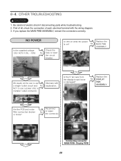
NO POWER DISPLAY PWB ASSEMBLY. Display PWB Connecting connector MAIN PWB~ Display PWB 29 [ 1. If you replace the MAIN PWB ASSEMBLY, reinsert the connectors correctly. Be careful of each electrical terminal with the wiring diagram. 3. First of all, check the connection of electric shock if disconnecting parts while troubleshooting. 2.
NO POWER DISPLAY PWB ASSEMBLY. Display PWB Connecting connector MAIN PWB~ Display PWB 29 [ 1. If you replace the MAIN PWB ASSEMBLY, reinsert the connectors correctly. Be careful of each electrical terminal with the wiring diagram. 3. First of all, check the connection of electric shock if disconnecting parts while troubleshooting. 2.
Service Manual
Page 54
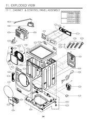
M410 A485 A455 A450 F210 A410 A140 A152 A139 A153 A150 A154 A141 A110 A111 A156 A151 A130 A134 A133 A390 A131 A310 A303 A300 A200 54 "The following parts are not illustrated" Description *Owner's Manual Loc No. G001 *Energy Label G002 *Service Manual Printed materials *Label,Circuit *Quick Start Guides G004 G005 G006 *Installation Sheet G007 *Non-Skid Pads G010 F215 F211 A102 A103 F110 A104 A105 A101 A100 A430 A201 A220 A440 A155
M410 A485 A455 A450 F210 A410 A140 A152 A139 A153 A150 A154 A141 A110 A111 A156 A151 A130 A134 A133 A390 A131 A310 A303 A300 A200 54 "The following parts are not illustrated" Description *Owner's Manual Loc No. G001 *Energy Label G002 *Service Manual Printed materials *Label,Circuit *Quick Start Guides G004 G005 G006 *Installation Sheet G007 *Non-Skid Pads G010 F215 F211 A102 A103 F110 A104 A105 A101 A100 A430 A201 A220 A440 A155


