
Datasheet
Page 2
...that demand high bandwidth. An Enterprise-Level OS The LaCie 12big Rack Network is the ideal addition to back up without a drop in just one box. Redundant and Reliable The LaCie 12big Rack Network's multiple redundant fans and power supply can serve as an iSCSI target. If you ...run short on server performance. It supports both block and network-attached storage in performance. The 12big Rack Network's hardware R AID controller and its ...
...that demand high bandwidth. An Enterprise-Level OS The LaCie 12big Rack Network is the ideal addition to back up without a drop in just one box. Redundant and Reliable The LaCie 12big Rack Network's multiple redundant fans and power supply can serve as an iSCSI target. If you ...run short on server performance. It supports both block and network-attached storage in performance. The 12big Rack Network's hardware R AID controller and its ...
Datasheet
Page 4
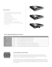
...CD LaCie 12big Rack Network Accessories: Accessory Name 1TB Spare drive 2TB Spare drive Cooling unit Power supply 12big Rack Serial 12big Rack Serial 12big Rack Serial Item # 131023 131024 131026 131027 131000 131001 131002 Description 1TB LaCie 12big Rack Network Enterprise drawer 2TB LaCie 12big Rack Network Enterprise drawer LaCie 12big Rack Network rescue cooling unit LaCie 12big Rack Network rescue power supply 6TB LaCie 12big Rack Serial to expand the 12big Rack Network 12TB LaCie 12big Rack Serial to expand the 12big Rack Network 24TB LaCie 12big Rack Serial to expand the 12big Rack...
...CD LaCie 12big Rack Network Accessories: Accessory Name 1TB Spare drive 2TB Spare drive Cooling unit Power supply 12big Rack Serial 12big Rack Serial 12big Rack Serial Item # 131023 131024 131026 131027 131000 131001 131002 Description 1TB LaCie 12big Rack Network Enterprise drawer 2TB LaCie 12big Rack Network Enterprise drawer LaCie 12big Rack Network rescue cooling unit LaCie 12big Rack Network rescue power supply 6TB LaCie 12big Rack Serial to expand the 12big Rack Network 12TB LaCie 12big Rack Serial to expand the 12big Rack Network 24TB LaCie 12big Rack Serial to expand the 12big Rack...
Datasheet
Page 5
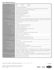
...),China: GB4943 - LaCie 12big Rack Network Item Number Capacity* Data Drive Bays Hard Disk Drives Processor Memory Memory Type DIMM Slots Enclosure Controller Network Protocols OS Support Front Panel Buttons and LED I/O Connectors Back Panel Buttons Input/Output PCI USB Serial Ports Video Port LAN Port Other Chassis Dimensions Weight Rack Support Cooling System Power Configuration Environment...
...),China: GB4943 - LaCie 12big Rack Network Item Number Capacity* Data Drive Bays Hard Disk Drives Processor Memory Memory Type DIMM Slots Enclosure Controller Network Protocols OS Support Front Panel Buttons and LED I/O Connectors Back Panel Buttons Input/Output PCI USB Serial Ports Video Port LAN Port Other Chassis Dimensions Weight Rack Support Cooling System Power Configuration Environment...

User Manual
Page 1
... Modules 20 2.6.2. Special Tools and Equipment 19 2.3.5. Mounting Rail Kit Installation 19 2.5. The LaCie 12big Rack Network System 7 1.2. ATX Server LEDs...11 1.4.2.1. Power Supply Output Loom 14 1.8. Unpacking the Enclosure System 18 2.3.3. Grounding Checks...21 2.9. Power On...22 3.2.1. LaCie 12big Rack Network System Configurations 9 1.4. Installation...17 2.1. Procedure...20 2.8. Multiple Power Supply Units 13 1.7.2. Ops Panel LEDs and Switches...23 3.4. Module Installation...20 2.6.1. Dummy...
... Modules 20 2.6.2. Special Tools and Equipment 19 2.3.5. Mounting Rail Kit Installation 19 2.5. The LaCie 12big Rack Network System 7 1.2. ATX Server LEDs...11 1.4.2.1. Power Supply Output Loom 14 1.8. Unpacking the Enclosure System 18 2.3.3. Grounding Checks...21 2.9. Power On...22 3.2.1. LaCie 12big Rack Network System Configurations 9 1.4. Installation...17 2.1. Procedure...20 2.8. Multiple Power Supply Units 13 1.7.2. Ops Panel LEDs and Switches...23 3.4. Module Installation...20 2.6.1. Dummy...

User Manual
Page 2
... Faults...32 4.5.4. Thermal Monitoring and Control 33 4.5.5. Dealing with Hardware Faults...34 4.8. Overview...35 5.2. Replacing a Module...35 5.3.1. Installing a Power Supply Unit 37 5.3.2. Replacing FB-DIMM Memory Modules 42 5.5.2. Replacing the Boot Drives...45 LaCie 12big Rack Network User Manual Table of Contents page 2 3.4.2. Activating the Locks 24 3.5. Troubleshooting & Problem Solving 26 4.1. Faulty Cords...26 4.1.1.2. Computer Doesn...
... Faults...32 4.5.4. Thermal Monitoring and Control 33 4.5.5. Dealing with Hardware Faults...34 4.8. Overview...35 5.2. Replacing a Module...35 5.3.1. Installing a Power Supply Unit 37 5.3.2. Replacing FB-DIMM Memory Modules 42 5.5.2. Replacing the Boot Drives...45 LaCie 12big Rack Network User Manual Table of Contents page 2 3.4.2. Activating the Locks 24 3.5. Troubleshooting & Problem Solving 26 4.1. Faulty Cords...26 4.1.1.2. Computer Doesn...
User Manual
Page 5
... battery is replaced by an incorrect type. CAUTION: There is a danger of the enclosure top cover or the power supply mounting cage must be used with the LaCie 12big Rack Network enclosure, this system does not support their use , by rotating the lock 90° to the "locked" ... to unused drive bays. Ensure that it has become damaged in a Power Supply Mounting Cage. CAUTION: Do not remove covers from a power supply input voltage range of electric shock inside. Safety ✦✦ The LaCie 12big Rack Network unit must not be operated from the PSU. The system must only...
... battery is replaced by an incorrect type. CAUTION: There is a danger of the enclosure top cover or the power supply mounting cage must be used with the LaCie 12big Rack Network enclosure, this system does not support their use , by rotating the lock 90° to the "locked" ... to unused drive bays. Ensure that it has become damaged in a Power Supply Mounting Cage. CAUTION: Do not remove covers from a power supply input voltage range of electric shock inside. Safety ✦✦ The LaCie 12big Rack Network unit must not be operated from the PSU. The system must only...

User Manual
Page 6
... temperature for each unit and the rack. ✦✦ Each Power Supply Unit has an earth leakage current of units installed in a rack. ✦✦ The rack construction must be capable of supporting the...LaCie 12big Rack Network User Manual Foreword page 6 Rack System Safety Precautions The following safety requirements must be considered when the unit is 35°C. ✦✦ The rack should have a safe electrical distribution system. Earth connection essential before loading the chassis into consideration the total earth leakage current from all the power supplies...
... temperature for each unit and the rack. ✦✦ Each Power Supply Unit has an earth leakage current of units installed in a rack. ✦✦ The rack construction must be capable of supporting the...LaCie 12big Rack Network User Manual Foreword page 6 Rack System Safety Precautions The following safety requirements must be considered when the unit is 35°C. ✦✦ The rack should have a safe electrical distribution system. Earth connection essential before loading the chassis into consideration the total earth leakage current from all the power supplies...
User Manual
Page 8
... enclosure subsystem together with a set of the LaCie 12big Rack Network storage system provides one 4-channel SAS cable from 4 to section 1.4. An SAS Expander PCB, to branch from the SAS Expander PCB to the Motherboard or to 12 Drive Carrier modules with 3.5" drives installed, (See Fig. 09). A Power Supply Mounting Cage containing two 850W, 100-240V...
... enclosure subsystem together with a set of the LaCie 12big Rack Network storage system provides one 4-channel SAS cable from 4 to section 1.4. An SAS Expander PCB, to branch from the SAS Expander PCB to the Motherboard or to 12 Drive Carrier modules with 3.5" drives installed, (See Fig. 09). A Power Supply Mounting Cage containing two 850W, 100-240V...

User Manual
Page 9
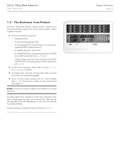
LaCie 12big Rack Network System Configurations The following LaCie 12big Rack Network system configurations are 12 drive bays at the front of the enclosure. NOTE: A Bay is fitted with 19 inch Rack mounting features which enables it to be fitted to standard 19 inch racks and uses 2 EIA units of a sheet metal enclosure ... form factor drives. Each drive bay accommodates a plug-in its carrier module. At the rear, the chassis assembly accommodates two Power Supply Units and ATX Server Subsystem. LaCie 12big Rack Network User Manual System Overview page 9 1.3. Enclosure Chassis
LaCie 12big Rack Network System Configurations The following LaCie 12big Rack Network system configurations are 12 drive bays at the front of the enclosure. NOTE: A Bay is fitted with 19 inch Rack mounting features which enables it to be fitted to standard 19 inch racks and uses 2 EIA units of a sheet metal enclosure ... form factor drives. Each drive bay accommodates a plug-in its carrier module. At the rear, the chassis assembly accommodates two Power Supply Units and ATX Server Subsystem. LaCie 12big Rack Network User Manual System Overview page 9 1.3. Enclosure Chassis
User Manual
Page 13
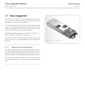
... completed within 10 minutes from removal of the subsystem core product. LaCie 12big Rack Network User Manual System Overview page 13 1.7. Power Supply Unit A Power Supply Mounting Cage is not affected while you replace the faulty unit. A typical PSU is shown in the Power Supply Mounting Cage, providing dual power sources for the system so that if one PSU fails the...
... completed within 10 minutes from removal of the subsystem core product. LaCie 12big Rack Network User Manual System Overview page 13 1.7. Power Supply Unit A Power Supply Mounting Cage is not affected while you replace the faulty unit. A typical PSU is shown in the Power Supply Mounting Cage, providing dual power sources for the system so that if one PSU fails the...

User Manual
Page 14
... output from each fan Fig. 08 - LaCie 12big Rack Network User Manual System Overview page 14 1.7.2. Power Supply Output Loom The Power Supply output loom provides the following outputs: ✦✦ P1 ATX Motherboard main power connectors (24 pin). ✦✦ P2 Processor power connector (8 pin) ✦✦ P3 12V power connector ✦✦ P4 Peripheral power connector (2 x 4 pin). ✦✦ P5...
... output from each fan Fig. 08 - LaCie 12big Rack Network User Manual System Overview page 14 1.7.2. Power Supply Output Loom The Power Supply output loom provides the following outputs: ✦✦ P1 ATX Motherboard main power connectors (24 pin). ✦✦ P2 Processor power connector (8 pin) ✦✦ P3 12V power connector ✦✦ P4 Peripheral power connector (2 x 4 pin). ✦✦ P5...

User Manual
Page 17
.... Two Power Supply Units must be covered with the configuration requirements of 4 drives should become familiar with blanking plates. AC Power Cords. 2.2. LaCie 12big Rack Network Configuration Module Drive Bays Power Supply Modules Cooling Fans PCI Cards Location ALL drive bays must be fitted. ✦✦ When two PSUs are shown how to plan and install your LaCie 12big Rack Network system. LaCie 12big Rack Network User...
.... Two Power Supply Units must be covered with the configuration requirements of 4 drives should become familiar with blanking plates. AC Power Cords. 2.2. LaCie 12big Rack Network Configuration Module Drive Bays Power Supply Modules Cooling Fans PCI Cards Location ALL drive bays must be fitted. ✦✦ When two PSUs are shown how to plan and install your LaCie 12big Rack Network system. LaCie 12big Rack Network User...

User Manual
Page 18
... refer to set up and use your LaCie 12big Rack Network system. Planning Your Installation for a single person to ensure that : ✦✦ All LaCie 12big Rack Network enclosure drive bays must be left completely empty. The following : ✦✦ Standard AC power from an independent source or a rack Power Distribution Unit with a UPS (universal power supply). 2.3.2. Planning and Configuring Your Installation Before...
... refer to set up and use your LaCie 12big Rack Network system. Planning Your Installation for a single person to ensure that : ✦✦ All LaCie 12big Rack Network enclosure drive bays must be left completely empty. The following : ✦✦ Standard AC power from an independent source or a rack Power Distribution Unit with a UPS (universal power supply). 2.3.2. Planning and Configuring Your Installation Before...

User Manual
Page 20
... disconnected prior to removal of the enclosure system with front rails. 3. IMPORTANT INFO: Operation of the Power Supply Unit from the enclosure. Procedure 1. LaCie 12big Rack Network User Manual Installation page 20 2.5. Tighten rear screws. 5. Module Installation IMPORTANT INFO: LaCie 12big Rack Network enclosures are supplied and delivered populated with Backplane PCB, ATX Motherboard, Enclosure Management PCB, SAS Expander PCB, Ops...
... disconnected prior to removal of the enclosure system with front rails. 3. IMPORTANT INFO: Operation of the Power Supply Unit from the enclosure. Procedure 1. LaCie 12big Rack Network User Manual Installation page 20 2.5. Tighten rear screws. 5. Module Installation IMPORTANT INFO: LaCie 12big Rack Network enclosures are supplied and delivered populated with Backplane PCB, ATX Motherboard, Enclosure Management PCB, SAS Expander PCB, Ops...

User Manual
Page 21
... appropriate local and National standards to the rack is even more than a few minutes, the enclosure can overheat, causing power failure and data loss. CAUTION: Prior to removing the PSU from the Power Supply Mounting Cage in the enclosure: Please disconnect the power from the power supply, by either the mains switch (where ...10022;✦ If the subsystem is completely foolproof. CAUTION: If more than one product is fitted in place for more important, because the rack will then have a high "EARTH LEAKAGE CURRENT" ("TOUCH CURRENT"). LaCie 12big Rack Network User Manual 2.8.
... appropriate local and National standards to the rack is even more than a few minutes, the enclosure can overheat, causing power failure and data loss. CAUTION: Prior to removing the PSU from the Power Supply Mounting Cage in the enclosure: Please disconnect the power from the power supply, by either the mains switch (where ...10022;✦ If the subsystem is completely foolproof. CAUTION: If more than one product is fitted in place for more important, because the rack will then have a high "EARTH LEAKAGE CURRENT" ("TOUCH CURRENT"). LaCie 12big Rack Network User Manual 2.8.

User Manual
Page 22
...;✦ When the PSU is switched on restoration of the Ops Panel LEDs and related fault conditions. Power Supply LEDs and switches are firmly seated in Fig. 14. Power On CAUTION: Do not operate the subsystem until the ambient temperature is pressed (and the disk drive ...✦✦ If a fault occurs the Red LED will re-start ). Before You Begin Before powering up the enclosure please ensure that all the modules are shown in their correct bays. 3.2. NOTE: Please refer to Power On the enclosure. 1. LaCie 12big Rack Network User Manual Operation page 22 3. Fig. 14 -
...;✦ When the PSU is switched on restoration of the Ops Panel LEDs and related fault conditions. Power Supply LEDs and switches are firmly seated in Fig. 14. Power On CAUTION: Do not operate the subsystem until the ambient temperature is pressed (and the disk drive ...✦✦ If a fault occurs the Red LED will re-start ). Before You Begin Before powering up the enclosure please ensure that all the modules are shown in their correct bays. 3.2. NOTE: Please refer to Power On the enclosure. 1. LaCie 12big Rack Network User Manual Operation page 22 3. Fig. 14 -

User Manual
Page 25
Power Down To power the enclosure down, either ✦✦ Switch off the Power Supply Unit(s) installed in the enclosure by pressing the Power push-button on the Ops Panel assembly (shown in Fig. 17) for complete isolation. Operation page 25 LaCie 12big Rack Network User Manual 3.5. or ✦✦ Remove AC mains at the power source IMPORTANT INFO: Disconnect both power cords for approximately 3 seconds.
Power Down To power the enclosure down, either ✦✦ Switch off the Power Supply Unit(s) installed in the enclosure by pressing the Power push-button on the Ops Panel assembly (shown in Fig. 17) for complete isolation. Operation page 25 LaCie 12big Rack Network User Manual 3.5. or ✦✦ Remove AC mains at the power source IMPORTANT INFO: Disconnect both power cords for approximately 3 seconds.

User Manual
Page 26
... to 4.3. There is independent monitoring for a replacement. 4.1.1.2. Alarm Sounds On Power Up Please refer to diagnose problems within the Power Supply and Cooling Fans. Check that the interface cables from the LaCie 12big Rack Network enclosure to the host computer are illuminated (Amber). Computer Doesn't Recognize the LaCie 12big Rack Network Subsystem 1. Note that Drive Carrier Modules have wired up Problems...
... to 4.3. There is independent monitoring for a replacement. 4.1.1.2. Alarm Sounds On Power Up Please refer to diagnose problems within the Power Supply and Cooling Fans. Check that the interface cables from the LaCie 12big Rack Network enclosure to the host computer are illuminated (Amber). Computer Doesn't Recognize the LaCie 12big Rack Network Subsystem 1. Note that Drive Carrier Modules have wired up Problems...

User Manual
Page 27
... activated Fig. 17 - Power Supply Unit LEDs Under Normal conditions the bi-color Power On LEDs will be illuminated constant GREEN. ON; +12VOUT - ON, +12VOUT - NOTE: The Ops Panel is supplied as an integral part of the Drive Carrier Module LED which is lit Amber under Normal conditions (see section 4.6. LaCie 12big Rack Network User Manual Troubleshooting & Problem...
... activated Fig. 17 - Power Supply Unit LEDs Under Normal conditions the bi-color Power On LEDs will be illuminated constant GREEN. ON; +12VOUT - ON, +12VOUT - NOTE: The Ops Panel is supplied as an integral part of the Drive Carrier Module LED which is lit Amber under Normal conditions (see section 4.6. LaCie 12big Rack Network User Manual Troubleshooting & Problem...

User Manual
Page 32
... Cause Internal fault detected (e.g. Fan LED is a PSU error present there may be a communications problem with your LaCie 12big Rack Network system. Cause Action Any power fault. Check AC mains connections to cooling fans is correct and that Power Supply Unit. Troubleshooting The following sections describe common problems, with possible solutions, which could cause PSU overheating. Cooling...
... Cause Internal fault detected (e.g. Fan LED is a PSU error present there may be a communications problem with your LaCie 12big Rack Network system. Cause Action Any power fault. Check AC mains connections to cooling fans is correct and that Power Supply Unit. Troubleshooting The following sections describe common problems, with possible solutions, which could cause PSU overheating. Cooling...
