
UDS1100 - Quick Start Guide
Page 3
UDS1100 QUICK START CONTENTS What's In the Box 2 Pinouts 3 IP Addressing 4 Connect 5 Install the Deviceinstaller GUI 5 Assign IP Address 6-9 Add the Unit to the Device List 10 Configure the UDS1100 10 LEDs/Troubleshoot 11-12 Contact 13
UDS1100 QUICK START CONTENTS What's In the Box 2 Pinouts 3 IP Addressing 4 Connect 5 Install the Deviceinstaller GUI 5 Assign IP Address 6-9 Add the Unit to the Device List 10 Configure the UDS1100 10 LEDs/Troubleshoot 11-12 Contact 13
UDS1100 - Quick Start Guide
Page 5
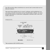
For more detailed information or alternative configuration methods, refer to connect, configure, and troubleshoot your unit using a network connection and our DeviceInstaller software. PINOUTS * *Not included in UDS1100 POE version WWW.LANTRONIX.COM 3 This Quick Start explains how to the User Guide on the CD. The UDS products allow serial devices to connect and communicate over an Ethernet network.
For more detailed information or alternative configuration methods, refer to connect, configure, and troubleshoot your unit using a network connection and our DeviceInstaller software. PINOUTS * *Not included in UDS1100 POE version WWW.LANTRONIX.COM 3 This Quick Start explains how to the User Guide on the CD. The UDS products allow serial devices to connect and communicate over an Ethernet network.
UDS1100 - User Guide
Page 5
... Commands 64 A: Troubleshootingand Contact Information 67 LEDs 67 Problems and Error Messages 68 Technical Support 70 B: Connections and Pinouts 71 Serial Port 71 Serial Connector Pinouts 71 Modem Cable 72 Network Port 73 Ethernet Connector Pinouts 74 Power Plug 74 C: Technical Specifications 75 D: Mounting Brackets 77 E: Alternative Ways to Assign an IP Address...
... Commands 64 A: Troubleshootingand Contact Information 67 LEDs 67 Problems and Error Messages 68 Technical Support 70 B: Connections and Pinouts 71 Serial Port 71 Serial Connector Pinouts 71 Modem Cable 72 Network Port 73 Ethernet Connector Pinouts 74 Power Plug 74 C: Technical Specifications 75 D: Mounting Brackets 77 E: Alternative Ways to Assign an IP Address...

UDS1100 - User Guide
Page 8
... unit to contact Lantronix Technical Support. C:Technical Specifications Lists technical specifications for installing your unit and getting it up and running using DeviceInstaller or a serial port connection. 4: Configuration Using Web- UDS1100 User Guide 8 B: Connections and Pinouts Provides descriptions and... Chapter Description 2: Introduction Describes the main features of the UDS and the protocols it supports. 3: Installation of UDS1100 Provides information for the UDS. D: Mounting Brackets Provides drawings and dimensions of connection hardware. 1: Using This Guide...
... unit to contact Lantronix Technical Support. C:Technical Specifications Lists technical specifications for installing your unit and getting it up and running using DeviceInstaller or a serial port connection. 4: Configuration Using Web- UDS1100 User Guide 8 B: Connections and Pinouts Provides descriptions and... Chapter Description 2: Introduction Describes the main features of the UDS and the protocols it supports. 3: Installation of UDS1100 Provides information for the UDS. D: Mounting Brackets Provides drawings and dimensions of connection hardware. 1: Using This Guide...

UDS1100 - User Guide
Page 15
... in the figure above. Connect an Ethernet cable to the serial device. Note: See the sections that was included in the packaging. For the UDS1100-POE version, power is 9-30 VDC (center +) or 10-24 VAC (1.5W maximum power required). 5. Note: The required input voltage for ...details about connectors and pinouts. 1. 3: Installation of UDS1100 Figure 3-2. For non-POE UDS1100 unit, supply power to your unit using an 802.3af POE-compliant power source such as a POE mid-span or POE ...
... in the figure above. Connect an Ethernet cable to the serial device. Note: See the sections that was included in the packaging. For the UDS1100-POE version, power is 9-30 VDC (center +) or 10-24 VAC (1.5W maximum power required). 5. Note: The required input voltage for ...details about connectors and pinouts. 1. 3: Installation of UDS1100 Figure 3-2. For non-POE UDS1100 unit, supply power to your unit using an 802.3af POE-compliant power source such as a POE mid-span or POE ...
UDS1100 - User Guide
Page 71
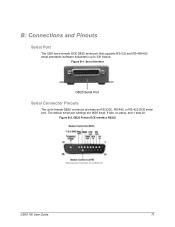
Serial Interface DB25 Serial Port Serial Connector Pinouts The unit's female DB25 connector provides an RS-232C, RS-485, or RS-422 DCE serial port. The default serial port settings are 9600 baud, 8 bits, no parity, and 1 stop bit. Figure B-2. UDS1100 User Guide 71 Figure B-1. DB25 Female DCE Interface RS232 *Optional power connection for non-POE unit. B: Connections and Pinouts Serial Port The UDS has a female DCE DB25 serial port that supports RS-232 and RS-485/422 serial standards (software selectable) up to 230 Kbaud.
Serial Interface DB25 Serial Port Serial Connector Pinouts The unit's female DB25 connector provides an RS-232C, RS-485, or RS-422 DCE serial port. The default serial port settings are 9600 baud, 8 bits, no parity, and 1 stop bit. Figure B-2. UDS1100 User Guide 71 Figure B-1. DB25 Female DCE Interface RS232 *Optional power connection for non-POE unit. B: Connections and Pinouts Serial Port The UDS has a female DCE DB25 serial port that supports RS-232 and RS-485/422 serial standards (software selectable) up to 230 Kbaud.

UDS1100 - User Guide
Page 72
Figure B-4. To configure the UDS using the DB9 serial port, you need only pin out the TXD, RXD, and GND signals. UDS1100 User Guide 72 DB25 Female Interface RS422 (4 wire mode) *Optional power connection for a DB25 to as a "Modem Cable". DB25 Female Interface RS485 (2 wire mode) Modem Cable When attaching the DB25 of the UDS to the DB9 com port on a PC, use a standard straight-through cable, often referred to DB9 straight-through serial cable (Lantronix Part No. 500-163). The figure below shows the pinouts for non-POE unit. B: Connections and Pinouts Figure B-3.
Figure B-4. To configure the UDS using the DB9 serial port, you need only pin out the TXD, RXD, and GND signals. UDS1100 User Guide 72 DB25 Female Interface RS422 (4 wire mode) *Optional power connection for a DB25 to as a "Modem Cable". DB25 Female Interface RS485 (2 wire mode) Modem Cable When attaching the DB25 of the UDS to the DB9 com port on a PC, use a standard straight-through cable, often referred to DB9 straight-through serial cable (Lantronix Part No. 500-163). The figure below shows the pinouts for non-POE unit. B: Connections and Pinouts Figure B-3.

UDS1100 - User Guide
Page 73
Network Interface RJ45 Ethernet Port Power Plug UDS1100 User Guide 73 Figure B-6. Wiring Diagram for Lantronix Modem Cable, Part No. 500-163 Network Port The standard UDS1100 non-POE version unit's back panel contains a power plug and an RJ45 (10/100) Ethernet port. it is powered through the Ethernet interface using 802.3af Power over Ethernet. B: Connections and Pinouts Figure B-5. The UDS1100-POE version does not have a power plug;
Network Interface RJ45 Ethernet Port Power Plug UDS1100 User Guide 73 Figure B-6. Wiring Diagram for Lantronix Modem Cable, Part No. 500-163 Network Port The standard UDS1100 non-POE version unit's back panel contains a power plug and an RJ45 (10/100) Ethernet port. it is powered through the Ethernet interface using 802.3af Power over Ethernet. B: Connections and Pinouts Figure B-5. The UDS1100-POE version does not have a power plug;

UDS1100 - User Guide
Page 74
RJ45 Ethernet Connector Power Plug Power input on the power plug is 9 -30 VDC (center +) or 10-24 VAC (1.5W maximum power required). UDS1100 User Guide 74 Figure B-7. B: Connections and Pinouts Ethernet Connector Pinouts The UDS1100 supports 10/100 Mbps half or full duplex Ethernet through an RJ45 connector.
RJ45 Ethernet Connector Power Plug Power input on the power plug is 9 -30 VDC (center +) or 10-24 VAC (1.5W maximum power required). UDS1100 User Guide 74 Figure B-7. B: Connections and Pinouts Ethernet Connector Pinouts The UDS1100 supports 10/100 Mbps half or full duplex Ethernet through an RJ45 connector.

UDS1100 - User Guide
Page 84
... 61 Flow, 42 Flush Mode, 51 Gateway, 38 Hardware Address, 13, 16 Host List Settings UDS1100 User Guide Setup Mode, 46 Web-Manager, 27 Inactivity Timeout, 53 Installation, 14 Installation of UDS1100, 14 Installing DeviceInstaller, 17 Interface Mode, 42 Internal Web Server, 12 IP address Requirement, 16...Brackets, 77 Netmask, 39 Network Settings, 24 Null Modem Cable, 72 Pack Control, 52 Package Contents, 14 Password for Telnet Configuration, 39 Pinouts, 71 Ethernet Connector, 74 Serial Connector, 71 Port Number, 43 Port Password, 54 Power plug, 73 Problems, 68 Protocols, 12 Redirection Software,...
... 61 Flow, 42 Flush Mode, 51 Gateway, 38 Hardware Address, 13, 16 Host List Settings UDS1100 User Guide Setup Mode, 46 Web-Manager, 27 Inactivity Timeout, 53 Installation, 14 Installation of UDS1100, 14 Installing DeviceInstaller, 17 Interface Mode, 42 Internal Web Server, 12 IP address Requirement, 16...Brackets, 77 Netmask, 39 Network Settings, 24 Null Modem Cable, 72 Pack Control, 52 Package Contents, 14 Password for Telnet Configuration, 39 Pinouts, 71 Ethernet Connector, 74 Serial Connector, 71 Port Number, 43 Port Password, 54 Power plug, 73 Problems, 68 Protocols, 12 Redirection Software,...