
UDS1100-IAP - Multi-Master DF1 Protocol User Guide
Page 8
... the network. 1. The default parameters display. 3: Configuring Multi-Master DF1 As a member of Lantronix's Industrial Automation Protocol (IAP) suite of products, the Multi-Master DF1 firmware can be used Industrial Serial Protocols, including DF1. The Setup Mode screen displays. You must configure certain parameters before the IAP Device Server can use a Telnet connection to port 9999 and the unit's IP address. 2. Multi-Master DF1 Protocol User Guide 7
... the network. 1. The default parameters display. 3: Configuring Multi-Master DF1 As a member of Lantronix's Industrial Automation Protocol (IAP) suite of products, the Multi-Master DF1 firmware can be used Industrial Serial Protocols, including DF1. The Setup Mode screen displays. You must configure certain parameters before the IAP Device Server can use a Telnet connection to port 9999 and the unit's IP address. 2. Multi-Master DF1 Protocol User Guide 7
APS: Modbus Protocol User Guide
Page 11
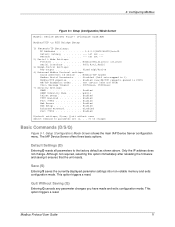
... Server configuration menu. This option triggers a reset. Modbus Protocol User Guide 11 Enabled (new MB/TCP requests queued in FIFO) MB/TCP Exception Codes . . . . The IAP Device Server offers three basic options. Save (S) Entering S saves the currently displayed parameter settings into non-volatile memory and exits configuration mode. Disabled (Id=0 auto-mapped to change . public Telnet Setup Enabled TFTP Download Enabled Port 77FEh Enabled...
... Server configuration menu. This option triggers a reset. Modbus Protocol User Guide 11 Enabled (new MB/TCP requests queued in FIFO) MB/TCP Exception Codes . . . . The IAP Device Server offers three basic options. Save (S) Entering S saves the currently displayed parameter settings into non-volatile memory and exits configuration mode. Disabled (Id=0 auto-mapped to change . public Telnet Setup Enabled TFTP Download Enabled Port 77FEh Enabled...

APS: Modbus Protocol User Guide
Page 13
... with the software-related details of settings, a warning displays. Wait for half-duplex radio modems. RTS/CTS Mode (1=Fixed 2=Variable) Answer 1 and the IAP Device Server output is always done on CH1 with a direct RS232 cable, as each end only asserts its RTS control signal to another IAP Device Server. Answering Y causes the IAP Device Server to support this is wired properly...
... with the software-related details of settings, a warning displays. Wait for half-duplex radio modems. RTS/CTS Mode (1=Fixed 2=Variable) Answer 1 and the IAP Device Server output is always done on CH1 with a direct RS232 cable, as each end only asserts its RTS control signal to another IAP Device Server. Answering Y causes the IAP Device Server to support this is wired properly...
APS: Modbus Protocol User Guide
Page 15
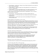
... error, as the reason the TCP socket failed to open , but no response was received in turn their transmitters off and their receivers back on. A safe value for the RS485 slave devices to pass through the serial port of the IAP Device Server, and the timer is returned: If slave-attached - Message Timeout (200-65000 msec) This sets...
... error, as the reason the TCP socket failed to open , but no response was received in turn their transmitters off and their receivers back on. A safe value for the RS485 slave devices to pass through the serial port of the IAP Device Server, and the timer is returned: If slave-attached - Message Timeout (200-65000 msec) This sets...
APS: Modbus Protocol User Guide
Page 17
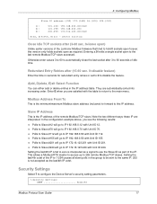
...part of the remote Modbus/TCP slave. Setting the last/4th IP octet to use the Slave ID as a signal to zero is the IP address of the IP. Setting the last/4th octet of idle time....123.201 with Unit ID 244. They are automatically sorted into increasing order. Entering a 0 holds a single socket open ) Unlike earlier versions of the Lantronix Modbus firmware that tried to ...Settings Select 7 to IP 172.16.123.244 with Unit ID 201. Polls to Slave #244 will go to configure the Device Server's security setting parameters. 7.Security Settings: SNMP Enabled Modbus Protocol User Guide...
...part of the remote Modbus/TCP slave. Setting the last/4th IP octet to use the Slave ID as a signal to zero is the IP address of the IP. Setting the last/4th octet of idle time....123.201 with Unit ID 244. They are automatically sorted into increasing order. Entering a 0 holds a single socket open ) Unlike earlier versions of the Lantronix Modbus firmware that tried to ...Settings Select 7 to IP 172.16.123.244 with Unit ID 201. Polls to Slave #244 will go to configure the Device Server's security setting parameters. 7.Security Settings: SNMP Enabled Modbus Protocol User Guide...

APS: Modbus Protocol User Guide
Page 20
... directly by Lantronix that firmware not supported." The TFTP method takes just a few seconds - With all protocol firmware, use our DeviceInstaller utility. These firmware files are important differences between the industrial protocol firmware files and the standard Lantronix firmware files. And although you will not be downloaded from the serial port. DeviceInstaller is a free utility program provided by Ethernet with the error "Sorry, that discovers, configures, upgrades...
... directly by Lantronix that firmware not supported." The TFTP method takes just a few seconds - With all protocol firmware, use our DeviceInstaller utility. These firmware files are important differences between the industrial protocol firmware files and the standard Lantronix firmware files. And although you will not be downloaded from the serial port. DeviceInstaller is a free utility program provided by Ethernet with the error "Sorry, that discovers, configures, upgrades...
APS: Modbus Protocol User Guide
Page 21
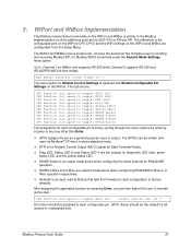
... configurable from the Setup Menu. Use serial connector (1=CH1 2=CH2) (1) ? The GPIOs can be written and read at startup that tells the firmware to reset configuration to factory defaults. Choose the serial port the firmware uses for Modem Control Settings is replaced with Modem/Configurable Pin Settings on the WiPort. Note: Channel 1 on WiBox only supports RS-232 while Channel 2 supports RS-232 and RS-422/RS-485 2/4-wire modes. The menu option for sending...
... configurable from the Setup Menu. Use serial connector (1=CH1 2=CH2) (1) ? The GPIOs can be written and read at startup that tells the firmware to reset configuration to factory defaults. Choose the serial port the firmware uses for Modem Control Settings is replaced with Modem/Configurable Pin Settings on the WiPort. Note: Channel 1 on WiBox only supports RS-232 while Channel 2 supports RS-232 and RS-422/RS-485 2/4-wire modes. The menu option for sending...

APS: Modbus Protocol User Guide
Page 25
... Control Output (MCO) signal for Data Terminal Ready. DCD is the Modem Control input (MCI) signal for Data set by cycling through the menu options by pressing Enter, you are then asked if the pin is inverted (active low). Choose the serial port, hence the firmware uses for Modem Control Settings has been replaced with Modem/Configurable Pin Settings on xPico supports RS-232 and RS-422/RS-485 2/4-wire modes while Channel...
... Control Output (MCO) signal for Data Terminal Ready. DCD is the Modem Control input (MCI) signal for Data set by cycling through the menu options by pressing Enter, you are then asked if the pin is inverted (active low). Choose the serial port, hence the firmware uses for Modem Control Settings has been replaced with Modem/Configurable Pin Settings on xPico supports RS-232 and RS-422/RS-485 2/4-wire modes while Channel...

APS: Modbus Protocol User Guide
Page 30
...- On the XPress DR-IAP, is often required between 0 to recognize need to short the TX+ to cross Ethernet and arrive error-free at least 2200 msec (2.2 sec). to 1000 msec (1 sec) or more per poll and another 1000 msec for 2 stop bits. An external Signal Ground connection is the external red switch set for a response. this : Is your cable set up correctly...
...- On the XPress DR-IAP, is often required between 0 to recognize need to short the TX+ to cross Ethernet and arrive error-free at least 2200 msec (2.2 sec). to 1000 msec (1 sec) or more per poll and another 1000 msec for 2 stop bits. An external Signal Ground connection is the external red switch set for a response. this : Is your cable set up correctly...

XPress-DR / XPress-DR-IAP - Product Brief
Page 1
... compliant Remotely Configure, Program, Monitor, and Manage: PLCs, drives, process controls, power monitoring equipment, barcode scanners, and other factory floor serial devices The XPress DR and XPress DR-IAP Device Servers enable virtually any industrial application. When used in the connected device. Included Windows® based con guration software simpli es the process of virtual serial ports, which can access network-enabled devices using t hese units, limited- The XPress DR-IAP installable communication drivers...
... compliant Remotely Configure, Program, Monitor, and Manage: PLCs, drives, process controls, power monitoring equipment, barcode scanners, and other factory floor serial devices The XPress DR and XPress DR-IAP Device Servers enable virtually any industrial application. When used in the connected device. Included Windows® based con guration software simpli es the process of virtual serial ports, which can access network-enabled devices using t hese units, limited- The XPress DR-IAP installable communication drivers...
XPress-DR / XPress-DR-IAP - Quick Start Guide
Page 2
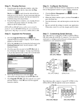
... DeviceInstaller window, select the installed device from the Lantronix support web page. See the user manual for your automation application. The Upgrade Firmware window displays. Click Upgrade FW File. Skip Step 5 if you have a DSTni-XPress DR.. Step 7: Connecting Serial Devices The cable below is a typical PC (COM1) to DSTni-XPress DR cable using the list button in the FW File field. 5. An error message indicates a problem with the network. Use the search buttons to press the Enter key...
... DeviceInstaller window, select the installed device from the Lantronix support web page. See the user manual for your automation application. The Upgrade Firmware window displays. Click Upgrade FW File. Skip Step 5 if you have a DSTni-XPress DR.. Step 7: Connecting Serial Devices The cable below is a typical PC (COM1) to DSTni-XPress DR cable using the list button in the FW File field. 5. An error message indicates a problem with the network. Use the search buttons to press the Enter key...

XPress-DR / XPress-DR-IAP - User Guide
Page 9
... Web Manager Page 3-4 3.3.1 Unit Configuration 3-5 3.3.2 Server Properties 3-6 3.3.3 Port Properties 3-7 3.3.4 Update Settings 3-9 3.3.5 Technical Support 3-9 3.4 Configuring via the Setup Mode Window 3-10 3.4.1 Using a Telnet Connection 3-10 3.4.2 Using the Serial Port 3-12 3.5 Server Configuration (Network Configuration 3-12 3.5.1 IP Address 3-12 3.5.2 Set Gateway IP Address 3-12 3.5.3 Netmask: Number of Bits for Host Part 3-12 3.5.4 Change Telnet configuration password 3-13 3.5.5 DHCP Naming 3-14 3.6 Channel 1 Configuration (Serial Port Parameters 3-15 3.6.1 Baudrate 3-15...
... Web Manager Page 3-4 3.3.1 Unit Configuration 3-5 3.3.2 Server Properties 3-6 3.3.3 Port Properties 3-7 3.3.4 Update Settings 3-9 3.3.5 Technical Support 3-9 3.4 Configuring via the Setup Mode Window 3-10 3.4.1 Using a Telnet Connection 3-10 3.4.2 Using the Serial Port 3-12 3.5 Server Configuration (Network Configuration 3-12 3.5.1 IP Address 3-12 3.5.2 Set Gateway IP Address 3-12 3.5.3 Netmask: Number of Bits for Host Part 3-12 3.5.4 Change Telnet configuration password 3-13 3.5.5 DHCP Naming 3-14 3.6 Channel 1 Configuration (Serial Port Parameters 3-15 3.6.1 Baudrate 3-15...
XPress-DR / XPress-DR-IAP - User Guide
Page 12
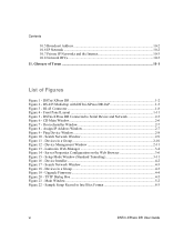
... Installer...4-2 Figure 17 - Sample Setup Record in a Group 4-3 Figure 19 - Glossary of Terms ...11-1 List of Figures Figure 1 - Setup Mode Window (Standard Tunneling 3-11 Figure 16 - Devices in Intel Hex Format 8-3 vi DSTni-XPress DR User Guide Ping Device Window 2-8 Figure 10 - Lantronix Web-Manager 3-4 Figure 14 - Upgrade Firmware 4-4 Figure 20 - Search Network Window 4-3 Figure 18 - Main Window ...5-2 Figure 22 - TFTP Dialog Box 4-5 Figure 21 - DSTni-XPress DR 1-2 Figure 2 - DSTni-XPress DR Connected to Serial...
... Installer...4-2 Figure 17 - Sample Setup Record in a Group 4-3 Figure 19 - Glossary of Terms ...11-1 List of Figures Figure 1 - Setup Mode Window (Standard Tunneling 3-11 Figure 16 - Devices in Intel Hex Format 8-3 vi DSTni-XPress DR User Guide Ping Device Window 2-8 Figure 10 - Lantronix Web-Manager 3-4 Figure 14 - Upgrade Firmware 4-4 Figure 20 - Search Network Window 4-3 Figure 18 - Main Window ...5-2 Figure 22 - TFTP Dialog Box 4-5 Figure 21 - DSTni-XPress DR 1-2 Figure 2 - DSTni-XPress DR Connected to Serial...

XPress-DR / XPress-DR-IAP - User Guide
Page 18
... factory environments, can unite any of installing protocols and configuring them for use Flash memory for maintenance-free, non-volatile storage which allows for fast system upgrades. 1.3 Network Protocols (Standard Tunneling) The DSTni-XPress DR uses TCP/IP protocols for data to flow in real time from all your plant devices up the unit using the serial port, or remotely over the network. The suite of equipment from the Lantronix...
... factory environments, can unite any of installing protocols and configuring them for use Flash memory for maintenance-free, non-volatile storage which allows for fast system upgrades. 1.3 Network Protocols (Standard Tunneling) The DSTni-XPress DR uses TCP/IP protocols for data to flow in real time from all your plant devices up the unit using the serial port, or remotely over the network. The suite of equipment from the Lantronix...

XPress-DR / XPress-DR-IAP - User Guide
Page 58
... the number of the router connected to your network. At this point, the screen display is to Using a Telnet Connection on ). Class B: 16 bits; The default serial port settings are displayed when you use a Telnet connection. The following parameters are 9600 baud, 8 bits, no parity, 1 stop bit, no flow control. 2. The gateway address must be set to other LAN segments. Class C: 8 bits. 3-12 DSTni-XPress DR User Guide Configure 3.4.2 Using the Serial Port...
... the number of the router connected to your network. At this point, the screen display is to Using a Telnet Connection on ). Class B: 16 bits; The default serial port settings are displayed when you use a Telnet connection. The following parameters are 9600 baud, 8 bits, no parity, 1 stop bit, no flow control. 2. The gateway address must be set to other LAN segments. Class C: 8 bits. 3-12 DSTni-XPress DR User Guide Configure 3.4.2 Using the Serial Port...

XPress-DR / XPress-DR-IAP - User Guide
Page 75
... protocol, since many of vendor specific protocol firmware. Table 19 - Firmware 4. Here is a list of the Standard Tunnel Protocol. Updating Protocol (Firmware) 4.1 Protocol Firmware The DSTni-XPress DR-IAP was designed to update the unit's internal operational code (*.ROM): via DeviceInstaller (the preferred way), via TFTP, via another unit, or via TFTP or DeviceInstaller. You can be changed. Check the Lantronix web site for Standard Tunnel...
... protocol, since many of vendor specific protocol firmware. Table 19 - Firmware 4. Here is a list of the Standard Tunnel Protocol. Updating Protocol (Firmware) 4.1 Protocol Firmware The DSTni-XPress DR-IAP was designed to update the unit's internal operational code (*.ROM): via DeviceInstaller (the preferred way), via TFTP, via another unit, or via TFTP or DeviceInstaller. You can be changed. Check the Lantronix web site for Standard Tunnel...

XPress-DR / XPress-DR-IAP - User Guide
Page 83
... a network failure or if a privileged user logs out the port being established, a message window will fail while the application is trying to use it . To view the Com Redirector release notes, go to Programs\Com Redirector and selecting Configuration. Start Redirector by going to Programs\Com Redirector and select Release Notes. DSTni-XPress DR User Guide 5-3 A similar message window will be displayed in these message windows...
... a network failure or if a privileged user logs out the port being established, a message window will fail while the application is trying to use it . To view the Com Redirector release notes, go to Programs\Com Redirector and selecting Configuration. Start Redirector by going to Programs\Com Redirector and select Release Notes. DSTni-XPress DR User Guide 5-3 A similar message window will be displayed in these message windows...

XPress-DR / XPress-DR-IAP - User Guide
Page 92
... Existing Firmware field. 6-4 DSTni-XPress DR User Guide Reason The unit or its power supply is the IP of the device server) PING X.X.X.X (X.X.X.X is damaged. When you get no previous problem, or possibly response. Solution Change power supplies. Confirm that Caps Lock is not disabled. You have Caps Lock on . The device server will most likely reason is attached to port 9999. You are flashing. Turn the...
... Existing Firmware field. 6-4 DSTni-XPress DR User Guide Reason The unit or its power supply is the IP of the device server) PING X.X.X.X (X.X.X.X is damaged. When you get no previous problem, or possibly response. Solution Change power supplies. Confirm that Caps Lock is not disabled. You have Caps Lock on . The device server will most likely reason is attached to port 9999. You are flashing. Turn the...

XPress-DR / XPress-DR-IAP - User Guide
Page 107
Binary to incoming connections over the network. DSTni-XPress DR User Guide 8-11 UDP 8.3.5 Connect Mode Connect Mode defines how the Device Server makes a connection, and how it reacts to Hexadecimal Conversion Table. DTR is hardwired to select Connect Mode options: Table 31 - Connect Mode Options Connect Mode Option Incoming Connection Never accept incoming Accept incoming with DTR (1) Accept unconditional Response Nothing (quiet) Character response (C=conn, D=disconn, N=unreachable) Startup...
Binary to incoming connections over the network. DSTni-XPress DR User Guide 8-11 UDP 8.3.5 Connect Mode Connect Mode defines how the Device Server makes a connection, and how it reacts to Hexadecimal Conversion Table. DTR is hardwired to select Connect Mode options: Table 31 - Connect Mode Options Connect Mode Option Incoming Connection Never accept incoming Accept incoming with DTR (1) Accept unconditional Response Nothing (quiet) Character response (C=conn, D=disconn, N=unreachable) Startup...

XPress-DR / XPress-DR-IAP - User Guide
Page 134
... coaxial cable. A bit (or binary digit) assumes the value of the OSI reference model, and are allocated from a BOOTP "server" node. Block A block is a variable-size piece of programs that a task can represent more than one bit. Ethernet, Token Ring and Arcnet LANs use baseband transmission. As opposed to higher level devices like routers. 11-2 DSTni-XPress DR User Guide...
... coaxial cable. A bit (or binary digit) assumes the value of the OSI reference model, and are allocated from a BOOTP "server" node. Block A block is a variable-size piece of programs that a task can represent more than one bit. Ethernet, Token Ring and Arcnet LANs use baseband transmission. As opposed to higher level devices like routers. 11-2 DSTni-XPress DR User Guide...


