
User Guide
Page 2
..., usefulness, suitability or performance of the Wi-Fi Alliance Corporation. All other countries. Lantronix shall have no obligation to update the information in this book may be transmitted or reproduced in the United States and other trademarks, servicemarks and trade names are registered trademarks of their respective owners. Intellectual Property © 2014 Lantronix, Inc. All rights reserved. xPico® Wi-Fi® Pi Plate User Guide 2 Lantronix...
..., usefulness, suitability or performance of the Wi-Fi Alliance Corporation. All other countries. Lantronix shall have no obligation to update the information in this book may be transmitted or reproduced in the United States and other trademarks, servicemarks and trade names are registered trademarks of their respective owners. Intellectual Property © 2014 Lantronix, Inc. All rights reserved. xPico® Wi-Fi® Pi Plate User Guide 2 Lantronix...
User Guide
Page 3
Table of Contents Intellectual Property 2 Warranty 2 Contacts 2 Disclaimer and Revisions 2 Revision History 2 List of Figures 4 List of Tables 4 1: Introduction 5 About this Guide 5 Additional Documentation 5 2: Pi Plate 6 Wi-Fi Kit Contents 6 Evaluation Board Description 6 Serial Port 1 8 Serial Port 2 8 Antenna Port 9 Power Supply 9 LEDs 9 USB 10 SPI and CP 10 Evaluation Board Schematic 12 xPico® Wi-Fi® Pi Plate User Guide 3
Table of Contents Intellectual Property 2 Warranty 2 Contacts 2 Disclaimer and Revisions 2 Revision History 2 List of Figures 4 List of Tables 4 1: Introduction 5 About this Guide 5 Additional Documentation 5 2: Pi Plate 6 Wi-Fi Kit Contents 6 Evaluation Board Description 6 Serial Port 1 8 Serial Port 2 8 Antenna Port 9 Power Supply 9 LEDs 9 USB 10 SPI and CP 10 Evaluation Board Schematic 12 xPico® Wi-Fi® Pi Plate User Guide 3
User Guide
Page 4
List of Figures Figure 2-1 xPico Wi-Fi Raspberry Pi Connectors and Jumpers 7 Figure 2-2 Evaluation Board Schematic (1 of 4 12 Figure 2-3 Evaluation Board Schematic (2 of 4 13 Figure 2-4 Evaluation Board Schematic (3 of 4 13 Figure 2-5 Evaluation Board Schematic (4 of 4 13 List of Tables Table 2-1 Evaluation Board Connectors, Header and Switches 7 Table 2-2 LEDs Signals ...9 xPico® Wi-Fi® Pi Plate User Guide 4
List of Figures Figure 2-1 xPico Wi-Fi Raspberry Pi Connectors and Jumpers 7 Figure 2-2 Evaluation Board Schematic (1 of 4 12 Figure 2-3 Evaluation Board Schematic (2 of 4 13 Figure 2-4 Evaluation Board Schematic (3 of 4 13 Figure 2-5 Evaluation Board Schematic (4 of 4 13 List of Tables Table 2-1 Evaluation Board Connectors, Header and Switches 7 Table 2-2 LEDs Signals ...9 xPico® Wi-Fi® Pi Plate User Guide 4
User Guide
Page 5
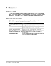
... information needed to use with their Raspberry Pi board-based product. xPico Integration Guide Provides hardware development requirements for the latest documentation and the following additional documentation. 1: Introduction About this Guide This user guide provides the information needed to xPico Wi-Fi technical specifications. Additional Documentation Visit the Lantronix web site at www.lantronix.com/support/documentation for integrating an xPico Wi-Fi module into a new board design. Document Description xPico Wi-Fi Pi Plate Quick Start Guide Instructions...
... information needed to use with their Raspberry Pi board-based product. xPico Integration Guide Provides hardware development requirements for the latest documentation and the following additional documentation. 1: Introduction About this Guide This user guide provides the information needed to xPico Wi-Fi technical specifications. Additional Documentation Visit the Lantronix web site at www.lantronix.com/support/documentation for integrating an xPico Wi-Fi module into a new board design. Document Description xPico Wi-Fi Pi Plate Quick Start Guide Instructions...
User Guide
Page 6
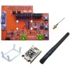
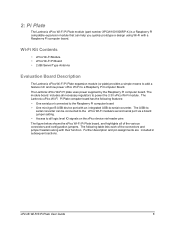
... (part number XPCW1001000RP-K) is a Raspberry Pi compatible expansion module that can be connected to the xPico Wi-Fi module's second serial port via a board jumper setting. Access to all logic level IO signals on the xPico device via header pins The figure below shows the xPico Wi-Fi Pi Plate board, and highlights all necessary regulators to - The Lantronix xPico Wi-Fi Pi Plate computer board has the following table lists each of the various connectors...
... (part number XPCW1001000RP-K) is a Raspberry Pi compatible expansion module that can be connected to the xPico Wi-Fi module's second serial port via a board jumper setting. Access to all logic level IO signals on the xPico device via header pins The figure below shows the xPico Wi-Fi Pi Plate board, and highlights all necessary regulators to - The Lantronix xPico Wi-Fi Pi Plate computer board has the following table lists each of the various connectors...
User Guide
Page 7
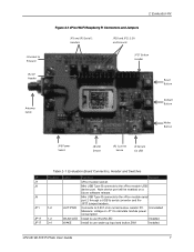
... power consumption Install to use WLAN LED Installed Install to use wake-up input and button,SW1 Installed xPico® Wi-Fi® Pi Plate User Guide 7 Uninstalled Measure voltage on a future software release. Mini USB Type B connects to PI board JP2 CP Header Antenna Cable 2: Evaluation Kit Figure 2-1 xPico Wi-Fi Raspberry Pi Connectors and Jumpers JP3 and JP5 Serial 1 Headers JP10 and JP11 3.3V and Ground JP17 Button Header Reset Button Default Button Wake Button JP6 Power Select J8 USB Device JP1 Current Sense J9 Serial...
... power consumption Install to use WLAN LED Installed Install to use wake-up input and button,SW1 Installed xPico® Wi-Fi® Pi Plate User Guide 7 Uninstalled Measure voltage on a future software release. Mini USB Type B connects to PI board JP2 CP Header Antenna Cable 2: Evaluation Kit Figure 2-1 xPico Wi-Fi Raspberry Pi Connectors and Jumpers JP3 and JP5 Serial 1 Headers JP10 and JP11 3.3V and Ground JP17 Button Header Reset Button Default Button Wake Button JP6 Power Select J8 USB Device JP1 Current Sense J9 Serial...

User Guide
Page 8
... CP6 CP7 CP8 RTS1 CTS1 Power 3.3V GND Function Default Install to route xPico Wi-Fi module second serial port Installed to J9 via the on board USB to serial converter Install to route xPico Wi-Fi module second serial port Installed to J9 via the on board USB to serial converter Install to use Defaults input and button, SW2 Installed Install to use Hardware Reset input and button, SW3 Installed Install position 1-2 to connect xPico module TXD1 to the Raspberry Pi computer board. Breakout header...
... CP6 CP7 CP8 RTS1 CTS1 Power 3.3V GND Function Default Install to route xPico Wi-Fi module second serial port Installed to J9 via the on board USB to serial converter Install to route xPico Wi-Fi module second serial port Installed to J9 via the on board USB to serial converter Install to use Defaults input and button, SW2 Installed Install to use Hardware Reset input and button, SW3 Installed Install position 1-2 to connect xPico module TXD1 to the Raspberry Pi computer board. Breakout header...

User Guide
Page 9
Download FTDI USB-to-serial drivers at this website: http://www.ftdichip.com/Drivers/VCP.htm Antenna Port The xPico Wi-Fi Pi Plate includes a bracket for a full description of the RF cable. LEDs The xPico evaluation board includes several LEDs for installation. See the xPico Wi-Fi Embedded Device Server User Guide for mounting the U.FL to reverse polarity SMA RF cable included with patterns indicating module status. Follow the procedure below...
Download FTDI USB-to-serial drivers at this website: http://www.ftdichip.com/Drivers/VCP.htm Antenna Port The xPico Wi-Fi Pi Plate includes a bracket for a full description of the RF cable. LEDs The xPico evaluation board includes several LEDs for installation. See the xPico Wi-Fi Embedded Device Server User Guide for mounting the U.FL to reverse polarity SMA RF cable included with patterns indicating module status. Follow the procedure below...
User Guide
Page 10
... connector connects to xPico Wi-Fi module serial port 2 via a USB to J8. The connections to the Raspberry Pi computer board are two USB connectors on how to use the SPI and CP ports. The xPico Wi-Fi has a USB device-side port that is connected to serial converter. Please refer to the Raspberry Pi computer board with a future firmware update. The USB device port will be connected to the xPico Wi-Fi Embedded Device Server User Guide for details on the xPico Wi-Fi Pi Plate...
... connector connects to xPico Wi-Fi module serial port 2 via a USB to J8. The connections to the Raspberry Pi computer board are two USB connectors on how to use the SPI and CP ports. The xPico Wi-Fi has a USB device-side port that is connected to serial converter. Please refer to the Raspberry Pi computer board with a future firmware update. The USB device port will be connected to the xPico Wi-Fi Embedded Device Server User Guide for details on the xPico Wi-Fi Pi Plate...

User Guide
Page 11
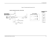
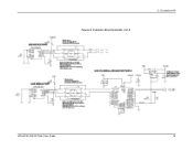
Evaluation Board Schematic Figure 2-2 Evaluation Board Schematic (1 of 4) 2: Evaluation Kit xPico® Wi-Fi® Pi Plate User Guide 12
Evaluation Board Schematic Figure 2-2 Evaluation Board Schematic (1 of 4) 2: Evaluation Kit xPico® Wi-Fi® Pi Plate User Guide 12
User Guide
Page 12
Figure 2-3 Evaluation Board Schematic (2 of 4) 2: Evaluation Kit xPico® Wi-Fi® Pi Plate User Guide 13
Figure 2-3 Evaluation Board Schematic (2 of 4) 2: Evaluation Kit xPico® Wi-Fi® Pi Plate User Guide 13
User Guide
Page 13
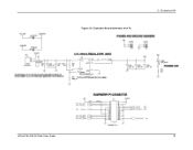
Figure 2-4 Evaluation Board Schematic (3 of 4) 2: Evaluation Kit xPico® Wi-Fi® Pi Plate User Guide 14
Figure 2-4 Evaluation Board Schematic (3 of 4) 2: Evaluation Kit xPico® Wi-Fi® Pi Plate User Guide 14
User Guide
Page 14
Figure 2-5 Evaluation Board Schematic (4 of 4) 2: Evaluation Kit xPico® Wi-Fi® Pi Plate User Guide 15
Figure 2-5 Evaluation Board Schematic (4 of 4) 2: Evaluation Kit xPico® Wi-Fi® Pi Plate User Guide 15
Quick Start Guide
Page 1
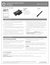
...-atFli 6789.... Connect power to another infrastructure network. MANUAL SETUP If you can manually setup the network in the U.S. in the WLAN Profiles menu. For Serial Port 2 operation, install jumpers on pins 5 to 6 and 7 to either xpicowifi.lantronix.com or 192.168.0.1. 9. This will scan for available networks. Open a web browser and navigate to 8 of JP17. The xPico Wi-Fi will display current information about the xPico Wi-Fi. Install the Lantronix® xPico® Wi-Fi® Pi plate into the...
...-atFli 6789.... Connect power to another infrastructure network. MANUAL SETUP If you can manually setup the network in the U.S. in the WLAN Profiles menu. For Serial Port 2 operation, install jumpers on pins 5 to 6 and 7 to either xpicowifi.lantronix.com or 192.168.0.1. 9. This will scan for available networks. Open a web browser and navigate to 8 of JP17. The xPico Wi-Fi will display current information about the xPico Wi-Fi. Install the Lantronix® xPico® Wi-Fi® Pi plate into the...


