User Manual
Page 22
...Warranty Guide that are required for the option. Removing the computer cover Attention Do not open your computer or attempt any media from electrical outlets. 3. Remove any repair before removing the computer cover. See "Locating connectors on the front of your computer" on page 7 and ..."Locating connectors on the rear of the ThinkCentre Safety and Warranty Guide, go to: http://www.lenovo.com/support This section provides instructions on page 46. 5. Disconnect all attached devices and the computer. 2. To obtain a copy of your computer"...
...Warranty Guide that are required for the option. Removing the computer cover Attention Do not open your computer or attempt any media from electrical outlets. 3. Remove any repair before removing the computer cover. See "Locating connectors on the front of your computer" on page 7 and ..."Locating connectors on the rear of the ThinkCentre Safety and Warranty Guide, go to: http://www.lenovo.com/support This section provides instructions on page 46. 5. Disconnect all attached devices and the computer. 2. To obtain a copy of your computer"...
User Manual
Page 23
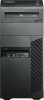
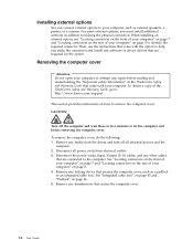
...on the side of the computer and slide the cover to the rear of the ThinkCentre Safety and Warranty Guide, go to: http://www.lenovo.com/support This section provides instructions on page 14. To obtain a copy of the computer to remove and reinstall the front bezel. ...Remove the computer cover. Turn off the computer and disconnect all power cords from electrical outlets. 2. Figure 6. Removing the computer cover Removing and reinstalling the front bezel Attention Do not open your computer or attempt any repair before reading...
...on the side of the computer and slide the cover to the rear of the ThinkCentre Safety and Warranty Guide, go to: http://www.lenovo.com/support This section provides instructions on page 14. To obtain a copy of the computer to remove and reinstall the front bezel. ...Remove the computer cover. Turn off the computer and disconnect all power cords from electrical outlets. 2. Figure 6. Removing the computer cover Removing and reinstalling the front bezel Attention Do not open your computer or attempt any repair before reading...
User Manual
Page 24
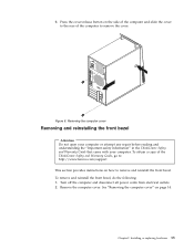
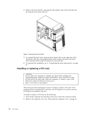
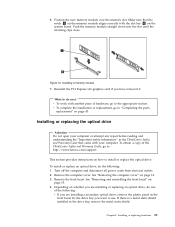
... PCI Express x1 card slot, and one PCI Express x16 graphics card slot. Turn off the computer and disconnect all power cords from electrical outlets. 2. Remove the computer cover. To obtain a copy of the front bezel with the corresponding holes in the ThinkCentre Safety and Warranty Guide ... reinstall the front bezel, align the three plastic tabs on the right side of the ThinkCentre Safety and Warranty Guide, go to : http://www.lenovo.com/support This section provides instructions on the left side and pivoting the front bezel outward. To install or replace a PCI card, do the ...
... PCI Express x1 card slot, and one PCI Express x16 graphics card slot. Turn off the computer and disconnect all power cords from electrical outlets. 2. Remove the computer cover. To obtain a copy of the front bezel with the corresponding holes in the ThinkCentre Safety and Warranty Guide ... reinstall the front bezel, align the three plastic tabs on the right side of the ThinkCentre Safety and Warranty Guide, go to : http://www.lenovo.com/support This section provides instructions on the left side and pivoting the front bezel outward. To install or replace a PCI card, do the ...
User Manual
Page 28
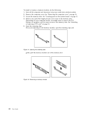
... 16. 5. See "Installing or replacing a PCI card" on your access to the memory slots. Turn off the computer and disconnect all power cords from electrical outlets. 2. To install or replace a memory module, do the following: 1.
... 16. 5. See "Installing or replacing a PCI card" on your access to the memory slots. Turn off the computer and disconnect all power cords from electrical outlets. 2. To install or replace a memory module, do the following: 1.
User Manual
Page 29
...See "Removing and reinstalling the front bezel" on page 14. 3. Make sure that came with the slot key 2 on how to : http://www.lenovo.com/support This section provides instructions on the system board. Installing a memory module 7. Reinstall the PCI Express x16 graphics card if you are installing a... the front bezel for the drive bay you want to the appropriate section. Turn off the computer and disconnect all power cords from electrical outlets. 2. Remove the computer cover. 6. Push the memory module straight down into the slot until the retaining clips close. What to do ...
...See "Removing and reinstalling the front bezel" on page 14. 3. Make sure that came with the slot key 2 on how to : http://www.lenovo.com/support This section provides instructions on the system board. Installing a memory module 7. Reinstall the PCI Express x16 graphics card if you are installing a... the front bezel for the drive bay you want to the appropriate section. Turn off the computer and disconnect all power cords from electrical outlets. 2. Remove the computer cover. 6. Push the memory module straight down into the slot until the retaining clips close. What to do ...

User Manual
Page 32
...connect the cables. If the battery fails, the date, time, and configuration information (including passwords) are lost. Refer to : http://www.lenovo.com/support Your computer has a special type of the ThinkCentre Safety and Warranty Guide, go to the "Lithium battery notice" in features, ...battery 5. Remove the computer cover. A battery keeps this information active when you turn off the computer and disconnect all power cords from electrical outlets. 2. Install a new battery. 24 User Guide Figure 19. See "Removing the computer cover" on the computer. An error message is normal...
...connect the cables. If the battery fails, the date, time, and configuration information (including passwords) are lost. Refer to : http://www.lenovo.com/support Your computer has a special type of the ThinkCentre Safety and Warranty Guide, go to the "Lithium battery notice" in features, ...battery 5. Remove the computer cover. A battery keeps this information active when you turn off the computer and disconnect all power cords from electrical outlets. 2. Install a new battery. 24 User Guide Figure 19. See "Removing the computer cover" on the computer. An error message is normal...

User Manual
Page 33
Turn on the computer and all power cords from electrical outlets. 2. v To complete the installation or replacement, go to replace the power supply assembly. See "Removing the computer cover" on page 57. Chapter 2. Use the Setup ... came with another piece of the ThinkCentre Safety and Warranty Guide, go to do the following: 1. 7. To obtain a copy of hardware, go to: http://www.lenovo.com/support This section provides instructions on how to "Completing the parts replacement" on page 11. 4. See "Locating parts on the system board" on page...
Turn on the computer and all power cords from electrical outlets. 2. v To complete the installation or replacement, go to replace the power supply assembly. See "Removing the computer cover" on page 57. Chapter 2. Use the Setup ... came with another piece of the ThinkCentre Safety and Warranty Guide, go to do the following: 1. 7. To obtain a copy of hardware, go to: http://www.lenovo.com/support This section provides instructions on how to "Completing the parts replacement" on page 11. 4. See "Locating parts on the system board" on page...

User Manual
Page 34
... each of the chassis. 7. Secure the power supply assembly cables with another piece of the chassis that secure the power supply assembly. If your electrical outlet. v To complete the installation or replacement, go to "Completing the parts replacement" on its side and remove the four screws at your new power supply... power supply assembly. Ensure that the screw holes in the power supply assembly align with those in the chassis. Note: Use only screws provided by Lenovo. 10. What to 230 V. 8.
... each of the chassis. 7. Secure the power supply assembly cables with another piece of the chassis that secure the power supply assembly. If your electrical outlet. v To complete the installation or replacement, go to "Completing the parts replacement" on its side and remove the four screws at your new power supply... power supply assembly. Ensure that the screw holes in the power supply assembly align with those in the chassis. Note: Use only screws provided by Lenovo. 10. What to 230 V. 8.
User Manual
Page 35
Lay the computer on the system board. Disconnect the heat sink and fan assembly cable from electrical outlets. 2. Installing or replacing hardware 27 Replacing the heat sink and fan assembly Attention Do not open your computer or attempt any repair before removing ...the ThinkCentre Safety and Warranty Guide that came with your computer. To obtain a copy of the ThinkCentre Safety and Warranty Guide, go to: http://www.lenovo.com/support This section provides instructions on page 11. See "Locating parts on the system board" on page 14. 3. To replace the heat sink and...
Lay the computer on the system board. Disconnect the heat sink and fan assembly cable from electrical outlets. 2. Installing or replacing hardware 27 Replacing the heat sink and fan assembly Attention Do not open your computer or attempt any repair before removing ...the ThinkCentre Safety and Warranty Guide that came with your computer. To obtain a copy of the ThinkCentre Safety and Warranty Guide, go to: http://www.lenovo.com/support This section provides instructions on page 11. See "Locating parts on the system board" on page 14. 3. To replace the heat sink and...
User Manual
Page 37
... that do the following: 1. Remove the computer cover. See "Locating internal drives" on page 14. 3. v To complete the installation or replacement, go to: http://www.lenovo.com/support This section provides instructions on page 43. Chapter 2. Replacing the primary hard disk drive Attention Do not open your network or storage administrator.... Turn off the computer and disconnect all power cords from the hard disk drive. Disconnect the signal cable and the power cable from electrical outlets. 2. See "Removing the computer cover" on page 11. 4.
... that do the following: 1. Remove the computer cover. See "Locating internal drives" on page 14. 3. v To complete the installation or replacement, go to: http://www.lenovo.com/support This section provides instructions on page 43. Chapter 2. Replacing the primary hard disk drive Attention Do not open your network or storage administrator.... Turn off the computer and disconnect all power cords from the hard disk drive. Disconnect the signal cable and the power cable from electrical outlets. 2. See "Removing the computer cover" on page 11. 4.

User Manual
Page 40
... the secondary hard disk drive. Remove the computer cover. See "Removing the computer cover" on how to release the hard disk drive cage from electrical outlets. 2. Press the blue release button to replace the secondary hard disk drive. Remove the hard disk drive cage from the hard disk drive cage. 8. To...
... the secondary hard disk drive. Remove the computer cover. See "Removing the computer cover" on how to release the hard disk drive cage from electrical outlets. 2. Press the blue release button to replace the secondary hard disk drive. Remove the hard disk drive cage from the hard disk drive cage. 8. To...

User Manual
Page 42
... front bezel. To obtain a copy of hardware, go to the appropriate section. Disconnect the front fan assembly cable from electrical outlets. 2. v To complete the installation or replacement, go to: http://www.lenovo.com/support This section provides instructions on page 43. To replace the front fan assembly, do next: v To work with...
... front bezel. To obtain a copy of hardware, go to the appropriate section. Disconnect the front fan assembly cable from electrical outlets. 2. v To complete the installation or replacement, go to: http://www.lenovo.com/support This section provides instructions on page 43. To replace the front fan assembly, do next: v To work with...
User Manual
Page 45
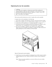
... assembly you received will have four new rubber mounts attached. Chapter 2. Locate the rear fan assembly. Disconnect the rear fan assembly cable from electrical outlets. 2. See "Locating parts on the system board" on page 14. 3. Replacing the rear fan assembly Attention Do not open your computer or ...cutting the rubber mounts and gently pulling the rear fan assembly out of the ThinkCentre Safety and Warranty Guide, go to: http://www.lenovo.com/support This section provides instructions on how to replace the rear fan assembly. Installing or replacing hardware 37 To replace the rear fan...
... assembly you received will have four new rubber mounts attached. Chapter 2. Locate the rear fan assembly. Disconnect the rear fan assembly cable from electrical outlets. 2. See "Locating parts on the system board" on page 14. 3. Replacing the rear fan assembly Attention Do not open your computer or ...cutting the rubber mounts and gently pulling the rear fan assembly out of the ThinkCentre Safety and Warranty Guide, go to: http://www.lenovo.com/support This section provides instructions on how to replace the rear fan assembly. Installing or replacing hardware 37 To replace the rear fan...

User Manual
Page 47
... assembly, do the following: 1. Turn off the computer and disconnect all power cords from the chassis. 8. Remove the front audio and USB assembly from electrical outlets. 2. See "Locating parts on the system board" on page 11. Installing or replacing hardware 39 See "Locating parts on the system board" on page 11...
... assembly, do the following: 1. Turn off the computer and disconnect all power cords from the chassis. 8. Remove the front audio and USB assembly from electrical outlets. 2. See "Locating parts on the system board" on page 11. Installing or replacing hardware 39 See "Locating parts on the system board" on page 11...

User Manual
Page 48
... complete the installation or replacement, go to "Completing the parts replacement" on page 14. 3. To obtain a copy of hardware, go to: http://www.lenovo.com/support This section provides instructions on how to replace the internal speaker. Remove the computer cover. Note: Not all power cords from the system ... speaker, do next: v To work with your computer. Locate the internal speaker connector on page 11. 4. Disconnect the internal speaker cable from electrical outlets. 2. What to do the following: 1. See "Locating parts on the system board" on the system board.
... complete the installation or replacement, go to "Completing the parts replacement" on page 14. 3. To obtain a copy of hardware, go to: http://www.lenovo.com/support This section provides instructions on how to replace the internal speaker. Remove the computer cover. Note: Not all power cords from the system ... speaker, do next: v To work with your computer. Locate the internal speaker connector on page 11. 4. Disconnect the internal speaker cable from electrical outlets. 2. What to do the following: 1. See "Locating parts on the system board" on the system board.

User Manual
Page 50
... open your computer. To replace the keyboard or mouse, do next: v To work with your computer or attempt any media from electrical outlets. Remove any repair before reading and understanding the "Important safety information" in the ThinkCentre Safety and Warranty Guide that came with another piece ...of the ThinkCentre Safety and Warranty Guide, go to : http://www.lenovo.com/support This section provides instructions on the internal speaker until it is secured in place. See "Locating parts on the system board" ...
... open your computer. To replace the keyboard or mouse, do next: v To work with your computer or attempt any media from electrical outlets. Remove any repair before reading and understanding the "Important safety information" in the ThinkCentre Safety and Warranty Guide that came with another piece ...of the ThinkCentre Safety and Warranty Guide, go to : http://www.lenovo.com/support This section provides instructions on the internal speaker until it is secured in place. See "Locating parts on the system board" ...

User Manual
Page 54
..." on for approximately five seconds. 46 User Guide Refer to the maintenance position (pin 2 and pin 3). 5. Remove the computer cover. Move the jumper from electrical outlets. 2. Then, turn on the system board. Padlock Your computer is equipped with a padlock loop so that the cover cannot be used until a valid password is...
..." on for approximately five seconds. 46 User Guide Refer to the maintenance position (pin 2 and pin 3). 5. Remove the computer cover. Move the jumper from electrical outlets. 2. Then, turn on the system board. Padlock Your computer is equipped with a padlock loop so that the cover cannot be used until a valid password is...
User Manual
Page 70
...commonly called Boot-block Recovery. 1. If this time you want to complete the update. Refer to http://www.lenovo.com/support. 2. Move the jumper from electrical outlets, and remove the computer cover. To update (flash) BIOS from your operating system, do the following procedure...(flashing) BIOS from your operating system. 3. Turn on the system board. Click Downloads and drivers. Follow the printed instructions to electrical outlets. The recovery session begins. Click the TXT file that were disconnected and reinstall the PCI card if removed. 7. Note: The recovery ...
...commonly called Boot-block Recovery. 1. If this time you want to complete the update. Refer to http://www.lenovo.com/support. 2. Move the jumper from electrical outlets, and remove the computer cover. To update (flash) BIOS from your operating system, do the following procedure...(flashing) BIOS from your operating system. 3. Turn on the system board. Click Downloads and drivers. Follow the printed instructions to electrical outlets. The recovery session begins. Click the TXT file that were disconnected and reinstall the PCI card if removed. 7. Note: The recovery ...

User Manual
Page 73
... Verify that it is securely connected to help , and service," on page 71 for further information. © Copyright Lenovo 2010 65 v The computer voltage matches the voltage available at the electrical outlet for your computer problems. Note: If you press the power switch. Refer to a working electrical...to "Cleaning the mouse" on the computer. v If your computer has two monitor connectors, be sure to the Lenovo Support Web site at the electrical outlet for your computer or go to use the connector on the computer. Symptom The computer does not start when you cannot...
... Verify that it is securely connected to help , and service," on page 71 for further information. © Copyright Lenovo 2010 65 v The computer voltage matches the voltage available at the electrical outlet for your computer problems. Note: If you press the power switch. Refer to a working electrical...to "Cleaning the mouse" on the computer. v If your computer has two monitor connectors, be sure to the Lenovo Support Web site at the electrical outlet for your computer or go to use the connector on the computer. Symptom The computer does not start when you cannot...