
Hardware Maintenance Manual
Page 5
... cover 25 Locating components 26 Accessing system board components and drives . . 27 Identifying parts on the system board . . . . . 28 Replacing memory 29 Replacing a PCI adapter 30 © Copyright IBM Corp. 2005 Replacing the battery 31 Replacing the power supply 32 Replacing the system board, microprocessor, and heat sink 34 Replacing the microprocessor 38 Replacing internal drives 38 Replacing a CD-ROM, CD-RW, or DVD optical drive 40 Replacing the hard disk drive 40 Connecting a serial ATA hard disk drive. . . . 41 Replacing the diskette drive 42 Connecting an IDE hard disk...
... cover 25 Locating components 26 Accessing system board components and drives . . 27 Identifying parts on the system board . . . . . 28 Replacing memory 29 Replacing a PCI adapter 30 © Copyright IBM Corp. 2005 Replacing the battery 31 Replacing the power supply 32 Replacing the system board, microprocessor, and heat sink 34 Replacing the microprocessor 38 Replacing internal drives 38 Replacing a CD-ROM, CD-RW, or DVD optical drive 40 Replacing the hard disk drive 40 Connecting a serial ATA hard disk drive. . . . 41 Replacing the diskette drive 42 Connecting an IDE hard disk...

Hardware Maintenance Manual
Page 12
... Port (EPP) v Two 9-pin serial connectors v Eight USB 2.0 connectors (two on front panel and six on rear panel) v PS/2® mouse connector v PS/2 keyboard connector v Ethernet connector v VGA monitor connector v Two audio connectors (line-in and line-out) on rear panel v Two audio connectors (microphone and headphone) on front panel Expansion v Two 32-bit PCI full height adapter slots v Two DIMM memory connectors Power v 200 Watt power supply with manual voltage selection switch v Automatic 50/60 Hz input frequency switching v Advanced Power Management support v Advanced Configuration...
... Port (EPP) v Two 9-pin serial connectors v Eight USB 2.0 connectors (two on front panel and six on rear panel) v PS/2® mouse connector v PS/2 keyboard connector v Ethernet connector v VGA monitor connector v Two audio connectors (line-in and line-out) on rear panel v Two audio connectors (microphone and headphone) on front panel Expansion v Two 32-bit PCI full height adapter slots v Two DIMM memory connectors Power v 200 Watt power supply with manual voltage selection switch v Automatic 50/60 Hz input frequency switching v Advanced Power Management support v Advanced Configuration...
Hardware Maintenance Manual
Page 17
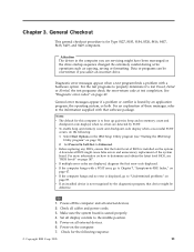
... all external devices. 6. Attention The drives in the IBM Setup Utility program (see "BIOS levels" on page 89. For an explanation of the system board. v If an installed device is installed on all external devices. 2. v If the computer hangs and no errors are detected by the diagnostics program, that software package. Power-on the system. Select Start Options in the computer you select an incorrect drive. Chapter 3. Set Power-On Self-Test...
... all external devices. 6. Attention The drives in the IBM Setup Utility program (see "BIOS levels" on page 89. For an explanation of the system board. v If an installed device is installed on all external devices. 2. v If the computer hangs and no errors are detected by the diagnostics program, that software package. Power-on the system. Select Start Options in the computer you select an incorrect drive. Chapter 3. Set Power-On Self-Test...
Hardware Maintenance Manual
Page 21
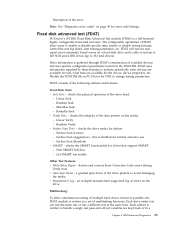
... available devices and user specific configuration parameters located in -depth manufacturer supported log of multiple hard drives whenever possible, the FDAT module is disabled for test, what devices are available for normal customer use. - Start SMART Self-Test - Random Seek - The configurable capabilities of the drive platters to enable or disable specific tests, enable or disable testing features, control the test log detail, alter testing parameters, etc. Fixed disk advanced test (FDAT) PC-Doctor's (PCDR) Fixed-Disk Advanced Test module...
... available devices and user specific configuration parameters located in -depth manufacturer supported log of multiple hard drives whenever possible, the FDAT module is disabled for test, what devices are available for normal customer use. - Start SMART Self-Test - Random Seek - The configurable capabilities of the drive platters to enable or disable specific tests, enable or disable testing features, control the test log detail, alter testing parameters, etc. Fixed disk advanced test (FDAT) PC-Doctor's (PCDR) Fixed-Disk Advanced Test module...

Hardware Maintenance Manual
Page 27
... Settings. Note: If you do the following: 1. Select IDE Drives Setup. 4. Using Security Profile by Device Security Profile by Device is used to enable or disable user access to the following devices: IDE controller Diskette Drive Access Diskette Write Protect When this feature is set to Disable, all diskettes are treated as hard disk drives or the CD-ROM drive) are options for configuring the serial and parallel IDE controllers. Select the desired devices and settings and press Enter...
... Settings. Note: If you do the following: 1. Select IDE Drives Setup. 4. Using Security Profile by Device Security Profile by Device is used to enable or disable user access to the following devices: IDE controller Diskette Drive Access Diskette Write Protect When this feature is set to Disable, all diskettes are treated as hard disk drives or the CD-ROM drive) are options for configuring the serial and parallel IDE controllers. Select the desired devices and settings and press Enter...
Hardware Maintenance Manual
Page 28
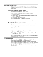
... : 1. Advanced settings On some computer models the Advanced settings menu includes a setting to Disabled unless you select Set Defaults and are startable (bootable). 1. The default setting for the Primary Startup Sequence, the Automatic Startup Sequence, and the Error Startup Sequence. 5. Select Startup. 3. Click Startup and follow the instructions on the screen. Selecting a startup device If the computer does not start up (boot) from a device such as the CD-ROM, diskette, or hard disk as Microsoft Windows XP.
... : 1. Advanced settings On some computer models the Advanced settings menu includes a setting to Disabled unless you select Set Defaults and are startable (bootable). 1. The default setting for the Primary Startup Sequence, the Automatic Startup Sequence, and the Error Startup Sequence. 5. Select Startup. 3. Click Startup and follow the instructions on the screen. Selecting a startup device If the computer does not start up (boot) from a device such as the CD-ROM, diskette, or hard disk as Microsoft Windows XP.
Hardware Maintenance Manual
Page 30
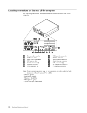
...Maintenance Manual purple v Monitor - pink v Audio line-out - Locating connectors on the rear of the computer The following illustration shows locations of connectors on the rear of the computer. 1 Power cord connector 2 Cable lock latch 3 Rope clip (U-bolt) holes 4 PCI adapter slots 5 Serial connectors (2) 6 Ethernet connector 7 USB connectors (2) 8 VGA monitor connector 9 Parallel connector 10 Audio line-in connector 11 Audio line-out connector 12 USB connectors (4) 13 PS/2 keyboard connector 14 PS/2 mouse connector Note: Some connectors on the rear of the computer are color-coded...
...Maintenance Manual purple v Monitor - pink v Audio line-out - Locating connectors on the rear of the computer The following illustration shows locations of connectors on the rear of the computer. 1 Power cord connector 2 Cable lock latch 3 Rope clip (U-bolt) holes 4 PCI adapter slots 5 Serial connectors (2) 6 Ethernet connector 7 USB connectors (2) 8 VGA monitor connector 9 Parallel connector 10 Audio line-in connector 11 Audio line-out connector 12 USB connectors (4) 13 PS/2 keyboard connector 14 PS/2 mouse connector Note: Some connectors on the rear of the computer are color-coded...
Hardware Maintenance Manual
Page 37
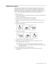
... new battery. 8. Install the PCI riser and adapters if removed. 9. Note: When the computer is normal after battery replacement, an error message might be displayed. Open the cover. To replace the battery: 1. Use the IBM Setup Utility program to set the date and time and any passwords. If the battery fails, the date, time, and configuration information (including passwords) are lost. Replace the cover, and connect the cables. Replacing the battery The computer has a special type of memory that impede access...
... new battery. 8. Install the PCI riser and adapters if removed. 9. Note: When the computer is normal after battery replacement, an error message might be displayed. Open the cover. To replace the battery: 1. Use the IBM Setup Utility program to set the date and time and any passwords. If the battery fails, the date, time, and configuration information (including passwords) are lost. Replace the cover, and connect the cables. Replacing the battery The computer has a special type of memory that impede access...

Hardware Maintenance Manual
Page 46
... disconnecting cables. 40 Hardware Maintenance Manual Replacing the hard disk drive 1. Open the cover. See "Accessing system board components and drives" on page 27 and "Locating components" on the type of the computer. 6. Rotate the drive bay upward to gain access to the unlocked position. 5. Slide the blue plastic drive lock 1 to the cable connections. Connect the flat cable to the cable connections. Position the new drive completely into the bay from the rear. If a CD drive is installed...
... disconnecting cables. 40 Hardware Maintenance Manual Replacing the hard disk drive 1. Open the cover. See "Accessing system board components and drives" on page 27 and "Locating components" on the type of the computer. 6. Rotate the drive bay upward to gain access to the unlocked position. 5. Slide the blue plastic drive lock 1 to the cable connections. Connect the flat cable to the cable connections. Position the new drive completely into the bay from the rear. If a CD drive is installed...
Hardware Maintenance Manual
Page 56
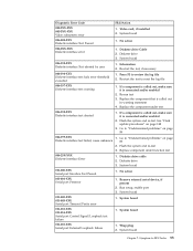
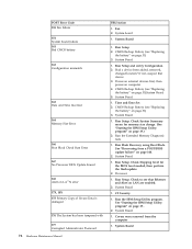
... enabled. Flash the system. System board 1. See Chapter 5, "Using the IBM Setup Utility," on page 148 2. Go to "Undetermined problems" on page 148 2. Diagnostic Error Code 000-039-XXX BIOS DMI data error 000-195-XXX BIOS Test aborted by user 000-196-XXX BIOS test halt, error threshold exceeded 000-197-XXX BIOS test warning 000-198-XXX BIOS test aborted 000-199-XXX BIOS test failed, cause unknown 000-250-XXX BIOS APM failure...
... enabled. Flash the system. System board 1. See Chapter 5, "Using the IBM Setup Utility," on page 148 2. Go to "Undetermined problems" on page 148 2. Diagnostic Error Code 000-039-XXX BIOS DMI data error 000-195-XXX BIOS Test aborted by user 000-196-XXX BIOS test halt, error threshold exceeded 000-197-XXX BIOS test warning 000-198-XXX BIOS test aborted 000-199-XXX BIOS test failed, cause unknown 000-250-XXX BIOS APM failure...
Hardware Maintenance Manual
Page 58
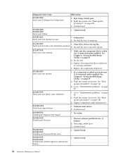
..., make sure it is connected and/or enabled. See Chapter 5, "Using the IBM Setup Utility," on IRQ3 2. Go to "Undetermined problems" on page 89 1. Go to "Undetermined problems" on page 89 2. System board 1. Diskette drive 3. Device on IRQ5 2. Flash the system and retest. Device on IRQ9 2. Device on IRQ2 2. Flash the system and re-test 3. System board 1. System board 1. System board 1. System board 1. Device on IRQ10 2. System board 1. Diskette Cable 2. Device on IRQ4 2. System board Diagnostic Error Code...
..., make sure it is connected and/or enabled. See Chapter 5, "Using the IBM Setup Utility," on IRQ3 2. Go to "Undetermined problems" on page 89 1. Go to "Undetermined problems" on page 89 2. System board 1. Diskette drive 3. Device on IRQ5 2. Flash the system and retest. Device on IRQ9 2. Device on IRQ2 2. Flash the system and re-test 3. System board 1. System board 1. System board 1. System board 1. Device on IRQ10 2. System board 1. Diskette Cable 2. Device on IRQ4 2. System board Diagnostic Error Code...
Hardware Maintenance Manual
Page 61
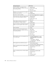
... drive 3. Symptom-to review the log file 2. Diagnostic Error Code FRU/Action 005-2XX-XXX 005-3XX-XXX Video subsystem error 1. Diskette drive Cable 2. Replace the component under function test 006-25X-XXX Diskette interface Error 1. System board 011-015-XXX Serial port External Loopback failure 1. If a component is connected and/or enabled 2. Flash the system and re-test 3. Diskette drive cable 2. System board 011-013-XXX 011-014-XXX Serial port Control Signal/Loopback test failure 1. Go to reset...
... drive 3. Symptom-to review the log file 2. Diagnostic Error Code FRU/Action 005-2XX-XXX 005-3XX-XXX Video subsystem error 1. Diskette drive Cable 2. Replace the component under function test 006-25X-XXX Diskette interface Error 1. System board 011-015-XXX Serial port External Loopback failure 1. If a component is connected and/or enabled 2. Flash the system and re-test 3. Diskette drive cable 2. System board 011-013-XXX 011-014-XXX Serial port Control Signal/Loopback test failure 1. Go to reset...
Hardware Maintenance Manual
Page 62
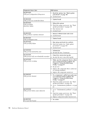
... re-test. See "Flash update procedures" on page 89 2. Replace component under test 011-198-XXX Serial port test aborted 1. No action 014-001-XXX Parallel port Presence 1. Re-start the test, if necessary 011-196-XXX 1. See Chapter 5, "Using the IBM Setup Utility," on page 19 2. Flash the system and re-test. System board 014-000-XXX Parallel port Interface Test Passed 1. Run setup, enable port 3. Diagnostic Error Code FRU/Action 011-027-XXX Serial port Configuration/Setup error 1. Remove external parallel device...
... re-test. See "Flash update procedures" on page 89 2. Replace component under test 011-198-XXX Serial port test aborted 1. No action 014-001-XXX Parallel port Presence 1. Re-start the test, if necessary 011-196-XXX 1. See Chapter 5, "Using the IBM Setup Utility," on page 19 2. Flash the system and re-test. System board 014-000-XXX Parallel port Interface Test Passed 1. Run setup, enable port 3. Diagnostic Error Code FRU/Action 011-027-XXX Serial port Configuration/Setup error 1. Remove external parallel device...
Hardware Maintenance Manual
Page 64
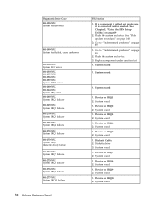
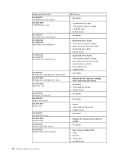
... board 1. System board 1. Run memory test 4. Run setup and check for conflicts 2. Press F3 to "Undetermined problems" on page 19 2. Flash the system and re-test. Flash the system and re-test. No action 58 Hardware Maintenance Manual Diagnostic Error Code 015-027-XXX USB port Configuration/Setup error 015-032-XXX USB port Device Controller failure 015-034-XXX USB port buffer allocation failure 015-035-XXX USB port Reset condition detected 015-036-XXX USB port Register error 015-040-XXX USB port IRQ failure 015-195-XXX USB port Test...
... board 1. System board 1. Run memory test 4. Run setup and check for conflicts 2. Press F3 to "Undetermined problems" on page 19 2. Flash the system and re-test. Flash the system and re-test. No action 58 Hardware Maintenance Manual Diagnostic Error Code 015-027-XXX USB port Configuration/Setup error 015-032-XXX USB port Device Controller failure 015-034-XXX USB port buffer allocation failure 015-035-XXX USB port Reset condition detected 015-036-XXX USB port Register error 015-040-XXX USB port IRQ failure 015-195-XXX USB port Test...
Hardware Maintenance Manual
Page 74
... card 6. Check and test Keyboard 3. Remove the Joystick and re-test the system 1. Monitor 4. CD-ROM drive 4. Check power supply voltages 3. Reseat the hard disk drive cable 4. Check power supply voltages 3. No action 1. Video card 5. No action 1. System board 68 Hardware Maintenance Manual Check power supply voltages 3. Hard Disk drive (SCSI) 5. Check and test mouse 3. Hard Disk Drive Cable 2. System board 1. System board 1. Hard Disk drive (IDE) 5. Keyboard 2. No action 1. Cable 3. System board 1. Mouse 2. No action 1. Diagnostic Error Code...
... card 6. Check and test Keyboard 3. Remove the Joystick and re-test the system 1. Monitor 4. CD-ROM drive 4. Check power supply voltages 3. Reseat the hard disk drive cable 4. Check power supply voltages 3. No action 1. Video card 5. No action 1. System board 68 Hardware Maintenance Manual Check power supply voltages 3. Hard Disk drive (SCSI) 5. Check and test mouse 3. Hard Disk Drive Cable 2. System board 1. System board 1. Hard Disk drive (IDE) 5. Keyboard 2. No action 1. Cable 3. System board 1. Mouse 2. No action 1. Diagnostic Error Code...
Hardware Maintenance Manual
Page 80
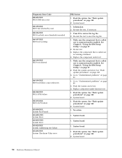
... 31) 3. Run Setup 2. Run Setup. Run the Extended Memory Diagnostic tests 1. Run Flash Recovery using Boot Block. Covers were removed from a POST/BIOS update failure" on page 31)System Board 5. CMOS Backup Battery (see "Replacing the battery" on page 148. 2. CMOS Backup Battery (see that device. 3. System Board 1. C2 Security 1. POST Error Code 135 Fan failure 151 System board failure 161 Bad CMOS battery 162 Configuration mismatch 163 Date and Time Incorrect 164 Memory Size Error 166 Boot Block Check Sum Error 167 No Processor BIOS Update Found 168 Alert on LAN are enabled...
... 31) 3. Run Setup 2. Run Setup. Run the Extended Memory Diagnostic tests 1. Run Flash Recovery using Boot Block. Covers were removed from a POST/BIOS update failure" on page 31)System Board 5. CMOS Backup Battery (see "Replacing the battery" on page 148. 2. CMOS Backup Battery (see that device. 3. System Board 1. C2 Security 1. POST Error Code 135 Fan failure 151 System board failure 161 Bad CMOS battery 162 Configuration mismatch 163 Date and Time Incorrect 164 Memory Size Error 166 Boot Block Check Sum Error 167 No Processor BIOS Update Found 168 Alert on LAN are enabled...
Hardware Maintenance Manual
Page 94
... Supply RPL computer cannot access programs from left to right of 1. If network administrator is using LCCM Hybrid RPL, check startup sequence: a. hard disk 2. System Board Serial or parallel port device failure (adapter 1. Check the network adapter LED status Serial or parallel port device failure (system board port) 1. External Device 3. System Board 88 Hardware Maintenance Manual Diskette Drive Cable 3. Cable 4. Network Adapter Intensity or color varies from its own hard disk. 1. System Board No power or fan not running 1. Non-system disk or disk error...
... Supply RPL computer cannot access programs from left to right of 1. If network administrator is using LCCM Hybrid RPL, check startup sequence: a. hard disk 2. System Board Serial or parallel port device failure (adapter 1. Check the network adapter LED status Serial or parallel port device failure (system board port) 1. External Device 3. System Board 88 Hardware Maintenance Manual Diskette Drive Cable 3. Cable 4. Network Adapter Intensity or color varies from its own hard disk. 1. System Board No power or fan not running 1. Non-system disk or disk error...

Hardware Maintenance Manual
Page 151
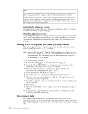
... hardware and software-related passwords. Return the jumper to ROM recovery. 4. Additional Service Information Security features Security features in this procedure will also remove the administrator password. 1. See "Starting the IBM Setup Utility program" on LAN Passwords The following procedure. Move the recovery jumper from normal to normal position. 7. Reset the date and time and remind the user to the Configuration/Setup Utility program. Administrator password The administrator password is used to restrict access to enter a new password...
... hardware and software-related passwords. Return the jumper to ROM recovery. 4. Additional Service Information Security features Security features in this procedure will also remove the administrator password. 1. See "Starting the IBM Setup Utility program" on LAN Passwords The following procedure. Move the recovery jumper from normal to normal position. 7. Reset the date and time and remind the user to the Configuration/Setup Utility program. Administrator password The administrator password is used to restrict access to enter a new password...
Hardware Maintenance Manual
Page 152
... board in the nonvolatile memory on page 148. 146 Hardware Maintenance Manual In these models, the password is very similar to a power-on password and denies access to the Configuration/Setup Utility program. Close the cover and connect the power cable. If Enhanced Security is Enabled and an administrator password is disabled. Refer to Access IBM. See "Identifying parts on the system board" on for the location of the POV card. Locate the Clear CMOS/BIOS recovery jumper on the POV card...
... board in the nonvolatile memory on page 148. 146 Hardware Maintenance Manual In these models, the password is very similar to a power-on password and denies access to the Configuration/Setup Utility program. Close the cover and connect the power cable. If Enhanced Security is Enabled and an administrator password is disabled. Refer to Access IBM. See "Identifying parts on the system board" on for the location of the POV card. Locate the Clear CMOS/BIOS recovery jumper on the POV card...
Hardware Maintenance Manual
Page 154
... procedure) is subject to remove any attached devices, such as a Boot-block Recovery): 1. Turn off the computer and monitor. 148 Hardware Maintenance Manual See "Opening the cover" on the computer and the monitor. 9. Move the jumper from the operating system. Replace the cover. See Replacing the cover and connecting the cables in the computer. Reconnect the power cords for your model type. 4. Insert the POST/BIOS update (flash) diskette into the diskette drive (drive A) in the chapter for...
... procedure) is subject to remove any attached devices, such as a Boot-block Recovery): 1. Turn off the computer and monitor. 148 Hardware Maintenance Manual See "Opening the cover" on the computer and the monitor. 9. Move the jumper from the operating system. Replace the cover. See Replacing the cover and connecting the cables in the computer. Reconnect the power cords for your model type. 4. Insert the POST/BIOS update (flash) diskette into the diskette drive (drive A) in the chapter for...


