

User Manual
Page 12
Many customers have handles covered with a soft material that does not insulate you when working with the power-off (EPO) switch, disconnecting switch, or electrical outlet. v If you . Remember: Another person must be a complete circuit to cause electrical shock. Remember: There must be hazardous. these instructions are in the installation and ...
Many customers have handles covered with a soft material that does not insulate you when working with the power-off (EPO) switch, disconnecting switch, or electrical outlet. v If you . Remember: Another person must be a complete circuit to cause electrical shock. Remember: There must be hazardous. these instructions are in the installation and ...

User Manual
Page 14
... system, such as to any obvious alterations. Note: The use coax or connector-outside shells on your clothing. Grounding requirements Electrical grounding of the electrical outlet can use of a grounding system is a difference in protective packages until they exceed the requirements noted here. 2. Proper grounding of the computer is especially useful...
... system, such as to any obvious alterations. Note: The use coax or connector-outside shells on your clothing. Grounding requirements Electrical grounding of the electrical outlet can use of a grounding system is a difference in protective packages until they exceed the requirements noted here. 2. Proper grounding of the computer is especially useful...

User Manual
Page 15
... equipment when there is hazardous. Turn everything OFF. 2. Remove all power cords to connectors. 4. v Connect all cables from outlet. 3. Turn device ON. To Connect 1. Attach signal cables to a properly wired and grounded electrical outlet. First, remove power cords from devices. Remove signal cables from power, telephone and communication cables is evidence of...
... equipment when there is hazardous. Turn everything OFF. 2. Remove all power cords to connectors. 4. v Connect all cables from outlet. 3. Turn device ON. To Connect 1. Attach signal cables to a properly wired and grounded electrical outlet. First, remove power cords from devices. Remove signal cables from power, telephone and communication cables is evidence of...

User Manual
Page 49
... sequence changed. Power-on page 53. 2. A power button LED is displayed, continue at the following : 1. Disconnect the power cord from the electrical outlet. Reconnect the power cord to the middle position. 4. Set all external devices. 2. a. c. v If the computer hangs and no errors are located ... boot up in the computer you hear beep codes during write operations such as copying, saving, or formatting. Press the power button. © Lenovo 2005, 2009. Portions © IBM Corp. 2005. 43 v Look for displayed error codes v Listen for beep codes v Look for this ...
... sequence changed. Power-on page 53. 2. A power button LED is displayed, continue at the following : 1. Disconnect the power cord from the electrical outlet. Reconnect the power cord to the middle position. 4. Set all external devices. 2. a. c. v If the computer hangs and no errors are located ... boot up in the computer you hear beep codes during write operations such as copying, saving, or formatting. Press the power button. © Lenovo 2005, 2009. Portions © IBM Corp. 2005. 43 v Look for displayed error codes v Listen for beep codes v Look for this ...

User Manual
Page 50
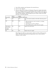
... and the microprocessor, one at a time, until the computer works correctly. 8. v Machine type and model v Processor or hard disk upgrades v Failure symptom - If the electrical outlet is OK. ON OFF Replace the system board ON ON Replace the power supply If the Diagnostic LEDs are considered identical only if they: 44... this the original reported failure? BIOS level v Operating system software - Observe the LEDs and refer to the following information to it has been working electrical outlet.
... and the microprocessor, one at a time, until the computer works correctly. 8. v Machine type and model v Processor or hard disk upgrades v Failure symptom - If the electrical outlet is OK. ON OFF Replace the system board ON ON Replace the power supply If the Diagnostic LEDs are considered identical only if they: 44... this the original reported failure? BIOS level v Operating system software - Observe the LEDs and refer to the following information to it has been working electrical outlet.
User Manual
Page 64
... the computer and disconnect all external devices. 2. OFF Replace the system board ON ON Replace the power supply If the Diagnostic LEDs are working electrical outlet. The power button LED is located on the front of the computer. Power-on the power supply at a time, until the computer works correctly. 58...
... the computer and disconnect all external devices. 2. OFF Replace the system board ON ON Replace the power supply If the Diagnostic LEDs are working electrical outlet. The power button LED is located on the front of the computer. Power-on the power supply at a time, until the computer works correctly. 58...

User Manual
Page 523
... reconnect the computer power cord to the computer and to the original position (pins 1 and 2). 9. Move the Clear CMOS/Recovery jumper back to an electrical outlet. Carefully follow the printed instructions to three minutes. After the update session completes, the series of beeps ends and the computer automatically turns off , open...
... reconnect the computer power cord to the computer and to the original position (pins 1 and 2). 9. Move the Clear CMOS/Recovery jumper back to an electrical outlet. Carefully follow the printed instructions to three minutes. After the update session completes, the series of beeps ends and the computer automatically turns off , open...