
Safety and Warranty guide
Page 9
... metal surface on , tripped over, or pinched by objects. 4 Safety and warranty guide Movement can cause the cord to fray, crack, or crimp. Handle adapters, memory modules, and other countries, the suitable types shall be safety approved. Never touch exposed circuitry. • Prevent others from the static-protective packaging and install...
... metal surface on , tripped over, or pinched by objects. 4 Safety and warranty guide Movement can cause the cord to fray, crack, or crimp. Handle adapters, memory modules, and other countries, the suitable types shall be safety approved. Never touch exposed circuitry. • Prevent others from the static-protective packaging and install...
Lenovo C3/C4/C5 Series User Guide
Page 9
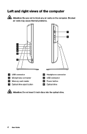
Blocked air vents may cause thermal problems. 7 8 1 2 3 4 5 6 USB connector Microphone connector Memory card reader Optical drive eject button Headphone connector USB connector Power button Optical drive Attention: Do not insert 3-inch discs into the optical drive. 4 User Guide Left and right views of the computer Attention: Be sure not to block any air vents on the computer.
Blocked air vents may cause thermal problems. 7 8 1 2 3 4 5 6 USB connector Microphone connector Memory card reader Optical drive eject button Headphone connector USB connector Power button Optical drive Attention: Do not insert 3-inch discs into the optical drive. 4 User Guide Left and right views of the computer Attention: Be sure not to block any air vents on the computer.

Lenovo C3/C4/C5 Series User Guide
Page 36
Hardware Replacement Guide This chapter contains the following topics: Ø Removing the stand base Ø Removing the foot cover Ø Replacing a memory module Ø Replacing the hard disk drive Ø Replacing the optical drive Ø Replacing the adapter Ø Replacing the keyboard and mouse User Guide 31
Hardware Replacement Guide This chapter contains the following topics: Ø Removing the stand base Ø Removing the foot cover Ø Replacing a memory module Ø Replacing the hard disk drive Ø Replacing the optical drive Ø Replacing the adapter Ø Replacing the keyboard and mouse User Guide 31

Lenovo C3/C4/C5 Series User Guide
Page 37
... certain mechanical parts can obtain one online from the Support Web site at http://support.lenovo.com. 32 User Guide Note: Use only parts provided by Lenovo®. This guide contains procedures for replacing the following parts: • Memory modules • Hard disk drive • Optical drive • Adapter • Keyboard, mouse (wired...
... certain mechanical parts can obtain one online from the Support Web site at http://support.lenovo.com. 32 User Guide Note: Use only parts provided by Lenovo®. This guide contains procedures for replacing the following parts: • Memory modules • Hard disk drive • Optical drive • Adapter • Keyboard, mouse (wired...

Lenovo C3/C4/C5 Series User Guide
Page 39
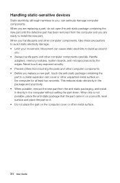
... the part to a metal expansion slot cover or other unpainted metal surface on the computer cover or other metal surface. 34 User Guide Handle adapters, memory modules, system boards, and microprocessors by the edges. Never touch any exposed circuitry. • Prevent others from the anti-static packaging, and install it directly...
... the part to a metal expansion slot cover or other unpainted metal surface on the computer cover or other metal surface. 34 User Guide Handle adapters, memory modules, system boards, and microprocessors by the edges. Never touch any exposed circuitry. • Prevent others from the anti-static packaging, and install it directly...

Lenovo C3/C4/C5 Series User Guide
Page 40
... safety information" in the Hardware Maintenance Manual (HMM) for this procedure. Lenovo recommends that you do the following: 1. Place the system on a soft flat surface for the computer. Remove any media (disks, CDs, or memory cards) from electrical outlets. 3. Replacing hardware Attention: Do not remove the...input/output (I/O) cables, and any repairs before removing the cover. Refer to the Support Web site at: http://support.lenovo.com Note: Use only parts provided by Lenovo. To obtain copies of the Safety and Warranty Guide or HMM, go to "Left and right views" and "Rear...
... safety information" in the Hardware Maintenance Manual (HMM) for this procedure. Lenovo recommends that you do the following: 1. Place the system on a soft flat surface for the computer. Remove any media (disks, CDs, or memory cards) from electrical outlets. 3. Replacing hardware Attention: Do not remove the...input/output (I/O) cables, and any repairs before removing the cover. Refer to the Support Web site at: http://support.lenovo.com Note: Use only parts provided by Lenovo. To obtain copies of the Safety and Warranty Guide or HMM, go to "Left and right views" and "Rear...
Lenovo C3/C4/C5 Series User Guide
Page 41
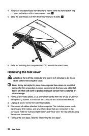
4. Removing the foot cover Attention: Turn off the computer and all attached devices. 2. Lenovo recommends that are connected to "Left and right views" and "Rear view" for this procedure. Remove the foot base. Disconnect all power cords from the ... the foot base". 36 User Guide Refer to reinstall the stand base. This includes power cords, input/output (I/O) cables, and any media (disks, CDs, or memory cards) from electrical outlets. 3. Refer to the computer. Unplug all cables attached to place the computer face-down the operating system, and turn off the...
4. Removing the foot cover Attention: Turn off the computer and all attached devices. 2. Lenovo recommends that are connected to "Left and right views" and "Rear view" for this procedure. Remove the foot base. Disconnect all power cords from the ... the foot base". 36 User Guide Refer to reinstall the stand base. This includes power cords, input/output (I/O) cables, and any media (disks, CDs, or memory cards) from electrical outlets. 3. Refer to the computer. Unplug all cables attached to place the computer face-down the operating system, and turn off the...
Lenovo C3/C4/C5 Series User Guide
Page 42
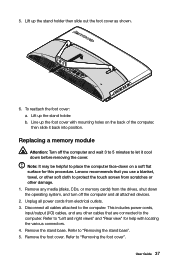
... up the foot cover with locating the various connectors. 4. Lenovo recommends that are connected to the computer. Refer to protect... off the computer and wait 3 to 5 minutes to the computer. Remove the stand base. 5. Replacing a memory module Attention: Turn off the computer and all cables attached to let it back into position. This includes power ...cords, input/output (I/O) cables, and any media (disks, CDs, or memory cards) from electrical outlets. 3. Lift up the stand holder then slide out the foot cover as shown. ...
... up the foot cover with locating the various connectors. 4. Lenovo recommends that are connected to the computer. Refer to protect... off the computer and wait 3 to 5 minutes to the computer. Remove the stand base. 5. Replacing a memory module Attention: Turn off the computer and all cables attached to let it back into position. This includes power ...cords, input/output (I/O) cables, and any media (disks, CDs, or memory cards) from electrical outlets. 3. Lift up the stand holder then slide out the foot cover as shown. ...
Lenovo C3/C4/C5 Series User Guide
Page 43
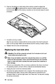
..." for this procedure. Note: It may be removed using the same procedure. 7. Make sure the latches lock the memory module in place. 8. Lenovo recommends that are connected to protect the touch screen from the drives, shut down before removing the cover. 6. To install... a memory module: Align the new memory module with the memory socket, then insert it from electrical outlets. 3. Disconnect all power cords from its...
..." for this procedure. Note: It may be removed using the same procedure. 7. Make sure the latches lock the memory module in place. 8. Lenovo recommends that are connected to protect the touch screen from the drives, shut down before removing the cover. 6. To install... a memory module: Align the new memory module with the memory socket, then insert it from electrical outlets. 3. Disconnect all power cords from its...

Lenovo C3/C4/C5 Series User Guide
Page 45
...soft flat surface for help with locating the various connectors. 4. This includes power cords, input/output (I/O) cables, and any media (disks, CDs, or memory cards) from electrical outlets. 3. Refer to push out the optical drive as shown. 40 User Guide Remove the stand base. Refer to "Removing the... stand base". 5. Refer to "Removing the foot cover". 6. Lenovo recommends that are connected to let it cool down the operating system, and turn off the computer and wait 3 to 5 minutes to the computer....
...soft flat surface for help with locating the various connectors. 4. This includes power cords, input/output (I/O) cables, and any media (disks, CDs, or memory cards) from electrical outlets. 3. Refer to push out the optical drive as shown. 40 User Guide Remove the stand base. Refer to "Removing the... stand base". 5. Refer to "Removing the foot cover". 6. Lenovo recommends that are connected to let it cool down the operating system, and turn off the computer and wait 3 to 5 minutes to the computer....

Lenovo C3/C4/C5 Series User Guide
Page 47
Align the new optical drive with the cover, and then push the cover back into the drive bay. 11. Remove any media (disks, CDs, or memory cards) from electrical outlet. Slide the new optical drive into position. Reattach the foot cover and stand base. 10. b. C340 / C345 / C440 / C445... / C540ğ C355 / C455ğ 42 User Guide Disconnect the adapter cable from the computer , then unplug the power cord from the drives, shut down the operating system, and...
Align the new optical drive with the cover, and then push the cover back into the drive bay. 11. Remove any media (disks, CDs, or memory cards) from electrical outlet. Slide the new optical drive into position. Reattach the foot cover and stand base. 10. b. C340 / C345 / C440 / C445... / C540ğ C355 / C455ğ 42 User Guide Disconnect the adapter cable from the computer , then unplug the power cord from the drives, shut down the operating system, and...
Lenovo C3/C4/C5 Series User Guide
Page 49
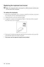
.... 44 User Guide Disconnect the defective keyboard cable from electrical outlets. 3. Unplug all attached devices. 2. To replace the keyboard: 1. Remove any media (disks, CDs, or memory cards) from the drives, shut down the computer, and turn off all power cords from the computer and connect the new keyboard cable to the...
.... 44 User Guide Disconnect the defective keyboard cable from electrical outlets. 3. Unplug all attached devices. 2. To replace the keyboard: 1. Remove any media (disks, CDs, or memory cards) from the drives, shut down the computer, and turn off all power cords from the computer and connect the new keyboard cable to the...

Lenovo C3/C4/C5 Series User Guide
Page 9
Blocked air vents may cause thermal problems. 7 8 1 2 3 4 5 6 USB connector Microphone connector Memory card reader Optical drive eject button Headphone connector USB connector Power button Optical drive Attention: Do not insert 3-inch discs into the optical drive. 4 User Guide Left and right views of the computer Attention: Be sure not to block any air vents on the computer.
Blocked air vents may cause thermal problems. 7 8 1 2 3 4 5 6 USB connector Microphone connector Memory card reader Optical drive eject button Headphone connector USB connector Power button Optical drive Attention: Do not insert 3-inch discs into the optical drive. 4 User Guide Left and right views of the computer Attention: Be sure not to block any air vents on the computer.
Lenovo C3/C4/C5 Series User Guide
Page 36
Hardware Replacement Guide This chapter contains the following topics: Ø Removing the stand base Ø Removing the foot cover Ø Replacing a memory module Ø Replacing the hard disk drive Ø Replacing the optical drive Ø Replacing the adapter Ø Replacing the keyboard and mouse User Guide 31
Hardware Replacement Guide This chapter contains the following topics: Ø Removing the stand base Ø Removing the foot cover Ø Replacing a memory module Ø Replacing the hard disk drive Ø Replacing the optical drive Ø Replacing the adapter Ø Replacing the keyboard and mouse User Guide 31

Lenovo C3/C4/C5 Series User Guide
Page 37
.... It is intended to be used by customers who are replacing Field Replaceable Units (FRUs). Note: Use only parts provided by Lenovo®. It does not apply to those computer models that was included with your computer or attempt any repairs before reading the "...trained service personnel who are replacing Customer Replaceable Units (CRUs) as well as parts. This guide contains procedures for replacing the following parts: • Memory modules • Hard disk drive • Optical drive • Adapter • Keyboard, mouse (wired) Safety information for step-by-step procedures...
.... It is intended to be used by customers who are replacing Field Replaceable Units (FRUs). Note: Use only parts provided by Lenovo®. It does not apply to those computer models that was included with your computer or attempt any repairs before reading the "...trained service personnel who are replacing Customer Replaceable Units (CRUs) as well as parts. This guide contains procedures for replacing the following parts: • Memory modules • Hard disk drive • Optical drive • Adapter • Keyboard, mouse (wired) Safety information for step-by-step procedures...
Lenovo C3/C4/C5 Series User Guide
Page 39
Handle adapters, memory modules, system boards, and microprocessors by the edges. Never touch any exposed circuitry. • Prevent others from touching the parts and other computer components. • ...
Handle adapters, memory modules, system boards, and microprocessors by the edges. Never touch any exposed circuitry. • Prevent others from touching the parts and other computer components. • ...

Lenovo C3/C4/C5 Series User Guide
Page 40
...down before reading the "Important safety information" in the Hardware Maintenance Manual (HMM) for the computer. Remove any media (disks, CDs, or memory cards) from the computer. 3. Lenovo recommends that you use a blanket, towel, or other soft cloth to the Support Web site at: http://support....lenovo.com Note: Use only parts provided by Lenovo. This includes power cords, input/output (I/O) cables, and any other damage. 1. Replacing hardware Attention: Do not remove the computer cover or...
...down before reading the "Important safety information" in the Hardware Maintenance Manual (HMM) for the computer. Remove any media (disks, CDs, or memory cards) from the computer. 3. Lenovo recommends that you use a blanket, towel, or other soft cloth to the Support Web site at: http://support....lenovo.com Note: Use only parts provided by Lenovo. This includes power cords, input/output (I/O) cables, and any other damage. 1. Replacing hardware Attention: Do not remove the computer cover or...

Lenovo C3/C4/C5 Series User Guide
Page 41
4. Unplug all cables attached to reinstall the stand base. Removing the foot cover Attention: Turn off the computer and all attached devices. 2. Lenovo recommends that are connected to let it aside. 6. Remove any other cables that you use a blanket, towel, or other damage. 1. Refer to ...soft cloth to "Removing the foot base". 36 User Guide This includes power cords, input/output (I/O) cables, and any media (disks, CDs, or memory cards) from the drives, shut down the operating system, and turn off the computer and wait 3 to 5 minutes to the computer. Slide the stand...
4. Unplug all cables attached to reinstall the stand base. Removing the foot cover Attention: Turn off the computer and all attached devices. 2. Lenovo recommends that are connected to let it aside. 6. Remove any other cables that you use a blanket, towel, or other damage. 1. Refer to ...soft cloth to "Removing the foot base". 36 User Guide This includes power cords, input/output (I/O) cables, and any media (disks, CDs, or memory cards) from the drives, shut down the operating system, and turn off the computer and wait 3 to 5 minutes to the computer. Slide the stand...

Lenovo C3/C4/C5 Series User Guide
Page 42
...: a. Remove any other damage. 1. Disconnect all attached devices. 2. Lenovo recommends that you use a blanket, towel, or other soft cloth to...the stand base". 5. This includes power cords, input/output (I/O) cables, and any media (disks, CDs, or memory cards) from electrical outlets. 3. Remove the foot cover. Line up the foot cover with mounting holes on a ...operating system, and turn off the computer and wait 3 to 5 minutes to the computer. Replacing a memory module Attention: Turn off the computer and all cables attached to let it back into position. User Guide...
...: a. Remove any other damage. 1. Disconnect all attached devices. 2. Lenovo recommends that you use a blanket, towel, or other soft cloth to...the stand base". 5. This includes power cords, input/output (I/O) cables, and any media (disks, CDs, or memory cards) from electrical outlets. 3. Remove the foot cover. Line up the foot cover with mounting holes on a ...operating system, and turn off the computer and wait 3 to 5 minutes to the computer. Replacing a memory module Attention: Turn off the computer and all cables attached to let it back into position. User Guide...

Lenovo C3/C4/C5 Series User Guide
Page 43
Reattach the foot cover and stand base. Lenovo recommends that are connected to place the computer face-down on a soft flat surface for help with the memory socket, then insert it cool down on both sides of the memory modules can be helpful to the computer. Push ...procedure. Remove any other cables that you use a blanket, towel, or other damage. 1. Refer to the computer. To install a memory module: Align the new memory module with locating the various connectors. 38 User Guide 6. Replacing the hard disk drive Attention: Turn off the computer and all power...
Reattach the foot cover and stand base. Lenovo recommends that are connected to place the computer face-down on a soft flat surface for help with the memory socket, then insert it cool down on both sides of the memory modules can be helpful to the computer. Push ...procedure. Remove any other cables that you use a blanket, towel, or other damage. 1. Refer to the computer. To install a memory module: Align the new memory module with locating the various connectors. 38 User Guide 6. Replacing the hard disk drive Attention: Turn off the computer and all power...


