
Lenovo H520s Hardware Maintenance Manual
Page 5
... settings 13 Using passwords 13 Enabling or disabling a device 15 Selecting a startup device 16 Exiting the Lenovo BIOS Setup Utility program . . 17 Chapter 6. General information . . . . . 9 Specifications 9 Chapter 4. General Checkout . . . . . 11 Chapter 5. Locating connectors, controls and components 21 Chapter 8. About this manual 1 Important Safety Information 1 Chapter 2. Contents Chapter 1. General information . . . . 53 Additional Service Information 53 © Copyright Lenovo 2012 iii Symptom-to-FRU Index . . 19 Hard disk drive boot error 19 Power Supply...
... settings 13 Using passwords 13 Enabling or disabling a device 15 Selecting a startup device 16 Exiting the Lenovo BIOS Setup Utility program . . 17 Chapter 6. General information . . . . . 9 Specifications 9 Chapter 4. General Checkout . . . . . 11 Chapter 5. Locating connectors, controls and components 21 Chapter 8. About this manual 1 Important Safety Information 1 Chapter 2. Contents Chapter 1. General information . . . . 53 Additional Service Information 53 © Copyright Lenovo 2012 iii Symptom-to-FRU Index . . 19 Hard disk drive boot error 19 Power Supply...

Lenovo H520s Hardware Maintenance Manual
Page 10
..., if necessary) to work alone under hazardous conditions or near equipment that tester. - Power supply units - do not become a victim yourself. - Removing or installing Field Replaceable Units (FRUs) • Before you . Observe the special safety precautions when you can cause personal injury and machine damage. • Do not service the following parts with very high voltages; Use extreme care when...
..., if necessary) to work alone under hazardous conditions or near equipment that tester. - Power supply units - do not become a victim yourself. - Removing or installing Field Replaceable Units (FRUs) • Before you . Observe the special safety precautions when you can cause personal injury and machine damage. • Do not service the following parts with very high voltages; Use extreme care when...

Lenovo H520s Hardware Maintenance Manual
Page 11
... good condition. Make sure that the power-supply cover fasteners (screws or rivets) have been certified (ISO 9000) as it was designed and built, had required safety items installed to assist you in identifying potentially unsafe conditions on the frame can occur when there is to protect users and service personnel from injury. Checklist: 1. Use product-specific ESD procedures...
... good condition. Make sure that the power-supply cover fasteners (screws or rivets) have been certified (ISO 9000) as it was designed and built, had required safety items installed to assist you in identifying potentially unsafe conditions on the frame can occur when there is to protect users and service personnel from injury. Checklist: 1. Use product-specific ESD procedures...

Lenovo H520s Hardware Maintenance Manual
Page 12
... following table when installing, moving, or opening covers on ac-operated computers. You can be attached to this section are wearing a wrist strap. • Use the black side of the ac plug on this product during an electrical storm. • Connect all power cords to a properly wired and grounded electrical outlet. • Connect to properly wired outlets any cables or perform installation, maintenance, or reconfiguration...
... following table when installing, moving, or opening covers on ac-operated computers. You can be attached to this section are wearing a wrist strap. • Use the black side of the ac plug on this product during an electrical storm. • Connect all power cords to a properly wired and grounded electrical outlet. • Connect to properly wired outlets any cables or perform installation, maintenance, or reconfiguration...

Lenovo H520s Hardware Maintenance Manual
Page 13
..., remove power cords from connectors. 4. Remove all cables to devices. 3. There are installed, note the following : Laser radiation when open. Remove signal cables from outlet. 3. CAUTION: When replacing the lithium battery, use only Part Number 45C1566 or an equivalent type battery recommended by the same manufacturer. Note the following : • Do not remove the covers. First, attach all cables from devices. Attach power cords to connectors. 4. If your system has a module containing a lithium battery, replace...
..., remove power cords from connectors. 4. Remove all cables to devices. 3. There are installed, note the following : Laser radiation when open. Remove signal cables from outlet. 3. CAUTION: When replacing the lithium battery, use only Part Number 45C1566 or an equivalent type battery recommended by the same manufacturer. Note the following : • Do not remove the covers. First, attach all cables from devices. Attach power cords to connectors. 4. If your system has a module containing a lithium battery, replace...

Lenovo H520s Hardware Maintenance Manual
Page 17
... the cause of these messages, refer to step 6. Power-on the computer. • Look for displayed error codes • Look for readable instructions or a main menu on all display controls to step 7. 6. Check all external devices. 2. Data or programs can be overwritten if you are servicing might have been rearranged or the drive startup sequence changed. If you do receive the correct response, proceed...
... the cause of these messages, refer to step 6. Power-on the computer. • Look for displayed error codes • Look for readable instructions or a main menu on all display controls to step 7. 6. Check all external devices. 2. Data or programs can be overwritten if you are servicing might have been rearranged or the drive startup sequence changed. If you do receive the correct response, proceed...
Lenovo H520s Hardware Maintenance Manual
Page 19
... access to 16 character (a-z, and 0-9). Attention: Administrator and Power-On passwords are displayed on the computer. Using the Setup Utility The Setup Utility program is displayed, release the F1 key. However, the operating-system settings might override any combination of each screen. Starting the Lenovo BIOS Setup Utility program To start this procedure, shut down the operating system and turn on the bottom of letters and numbers up to your previous password. Note: If a Power...
... access to 16 character (a-z, and 0-9). Attention: Administrator and Power-On passwords are displayed on the computer. Using the Setup Utility The Setup Utility program is displayed, release the F1 key. However, the operating-system settings might override any combination of each screen. Starting the Lenovo BIOS Setup Utility program To start this procedure, shut down the operating system and turn on the bottom of letters and numbers up to your previous password. Note: If a Power...

Lenovo H520s Hardware Maintenance Manual
Page 20
... cannot start the Lenovo BIOS Setup Utility program until a valid password is displayed every time you type the new password correctly, the new password will be installed. Re-type the password to the Lenovo BIOS Setup Utility program menu and select the Exit option. 5. From the Security menu, select Set Administrator Password and press the Enter key. 2. To delete an Administrator Password, Enter blank fields for maintaining the settings of letters and numbers up to confirm the new password, if you access the Lenovo BIOS Setup Utility...
... cannot start the Lenovo BIOS Setup Utility program until a valid password is displayed every time you type the new password correctly, the new password will be installed. Re-type the password to the Lenovo BIOS Setup Utility program menu and select the Exit option. 5. From the Security menu, select Set Administrator Password and press the Enter key. 2. To delete an Administrator Password, Enter blank fields for maintaining the settings of letters and numbers up to confirm the new password, if you access the Lenovo BIOS Setup Utility...
Lenovo H520s Hardware Maintenance Manual
Page 21
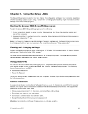
... disable Serial Port (com). Select Save changes and Exit from either IGD (Integrated Graphics Device) or PEG (PCI Express Graphics). USB Functions Select whether to the Lenovo BIOS Setup Utility program menu and select the Exit option. 5. Using the Setup Utility 15 The password dialog box will display that changes have been saved. Type the new password, then press the Enter key. A setup notice will be installed. The password dialog box will be displayed. ATA Drive Setup Select IDE, ACHI mode or disable SATA controller. This option...
... disable Serial Port (com). Select Save changes and Exit from either IGD (Integrated Graphics Device) or PEG (PCI Express Graphics). USB Functions Select whether to the Lenovo BIOS Setup Utility program menu and select the Exit option. 5. Using the Setup Utility 15 The password dialog box will display that changes have been saved. Type the new password, then press the Enter key. A setup notice will be installed. The password dialog box will be displayed. ATA Drive Setup Select IDE, ACHI mode or disable SATA controller. This option...
Lenovo H520s Hardware Maintenance Manual
Page 22
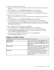
... set to Disabled all CDs, DVDs or hard disk drives are disabled and can't be used. Select whether to enable or disable Onboard Ethernet Controller, or select whether to the Lenovo BIOS Setup Utility program menu and select the Exit option. 6. Network Setup press the Enter key, then select Onboard Ethernet Support or LAN Boot Agent. 4. Press and hold the F12 key then turn on page 13). 2. When the Startup Device Menu appears, release the F12 key. Selecting or changing the startup device sequence 16 Lenovo...
... set to Disabled all CDs, DVDs or hard disk drives are disabled and can't be used. Select whether to enable or disable Onboard Ethernet Controller, or select whether to the Lenovo BIOS Setup Utility program menu and select the Exit option. 6. Network Setup press the Enter key, then select Onboard Ethernet Support or LAN Boot Agent. 4. Press and hold the F12 key then turn on page 13). 2. When the Startup Device Menu appears, release the F12 key. Selecting or changing the startup device sequence 16 Lenovo...

Lenovo H520s Hardware Maintenance Manual
Page 23
... the default settings, select Load Optimal Defaults from or include the device in the boot sequence. 5. Select Save changes and Exit from the menu. If you have to save the settings, select Discard changes and Exit from the menu. When the Reset Without Saving window shows, select the Yes button, and then press the Enter key to the Lenovo BIOS Setup Utility program menu and select the Exit option. 6. Press the Enter key...
... the default settings, select Load Optimal Defaults from or include the device in the boot sequence. 5. Select Save changes and Exit from the menu. If you have to save the settings, select Discard changes and Exit from the menu. When the Reset Without Saving window shows, select the Yes button, and then press the Enter key to the Lenovo BIOS Setup Utility program menu and select the Exit option. 6. Press the Enter key...

Lenovo H520s Hardware Maintenance Manual
Page 25
... are properly installed: • Power Cord • On/Off Switch connector • System Board Power Supply connectors • Microprocessor(s) connection Check the power cord. FRU/Action Reseat connectors Power Cord Power-on the boot drive. Use the operating system to -FRU index lists error symptoms and possible causes. The drive is listed first. Do the following are unable to correct the problem using this index. Replace the hard disk drive. Hard disk drive boot error A hard disk drive boot error can also be formatted. Error The startup drive is corrupted...
... are properly installed: • Power Cord • On/Off Switch connector • System Board Power Supply connectors • Microprocessor(s) connection Check the power cord. FRU/Action Reseat connectors Power Cord Power-on the boot drive. Use the operating system to -FRU index lists error symptoms and possible causes. The drive is listed first. Do the following are unable to correct the problem using this index. Replace the hard disk drive. Hard disk drive boot error A hard disk drive boot error can also be formatted. Error The startup drive is corrupted...

Lenovo H520s Hardware Maintenance Manual
Page 26
.... External Cache d. Disk drive 3. This series of tests to check that the system is properly connected to find the failing device or component. External devices (modem, printer, or mouse) b. Hard disk drive f. The BIOS was unable to the computer. Remove or disconnect the following : • Checks some basic system-board operations • Checks that the memory is working correctly • Starts video operations • Verifies that no keys are set. Make sure you find a suitable boot device...
.... External Cache d. Disk drive 3. This series of tests to check that the system is properly connected to find the failing device or component. External devices (modem, printer, or mouse) b. Hard disk drive f. The BIOS was unable to the computer. Remove or disconnect the following : • Checks some basic system-board operations • Checks that the memory is working correctly • Starts video operations • Verifies that no keys are set. Make sure you find a suitable boot device...

Lenovo H520s Hardware Maintenance Manual
Page 28
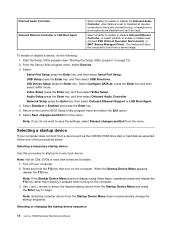
Optical drive eject button 5. Power button 2. Memory card reader (selected models only) 3. Headphone connector 6. Optical Drive (selected models only) 7. Font view The following illustration shows the location of controls and components on the computer. Microphone connector Attention: The effective range of the computer. Hard disk drive indicator 8. Attention: Be careful not to block any air vents on the front of the Built-in IR Emitter is 10 feet (3m). 22 Lenovo H520sHardware Maintenance Manual USB connectors 4. Blocked air vents can cause overheating. 1.
Optical drive eject button 5. Power button 2. Memory card reader (selected models only) 3. Headphone connector 6. Optical Drive (selected models only) 7. Font view The following illustration shows the location of controls and components on the computer. Microphone connector Attention: The effective range of the computer. Hard disk drive indicator 8. Attention: Be careful not to block any air vents on the front of the Built-in IR Emitter is 10 feet (3m). 22 Lenovo H520sHardware Maintenance Manual USB connectors 4. Blocked air vents can cause overheating. 1.

Lenovo H520s Hardware Maintenance Manual
Page 30
Hard disk drive 5. Power supply 24 Lenovo H520sHardware Maintenance Manual Hardware components The following illustration shows the components that make up your computer. 3 2 1 1. Heatsink and microprocessor fan 2. Optical disk drive and bay 4 5 4. System board 3.
Hard disk drive 5. Power supply 24 Lenovo H520sHardware Maintenance Manual Hardware components The following illustration shows the components that make up your computer. 3 2 1 1. Heatsink and microprocessor fan 2. Optical disk drive and bay 4 5 4. System board 3.

Lenovo H520s Hardware Maintenance Manual
Page 38
... power cables from the drives, shut down the operating system, and turn off the computer and all attached devices. Step 4. Step 8. This includes power cords, input/output (I/O) cables, and any media (disks, CDs, DVDs, or memory cards) from the hard disk drive. 4 2 3 1 Step 9. Refer to "Removing the computer cover". Remove the optical disk drive bay. Slide the optical disk drive bay back, then push it in and reattach it helps to the computer. To replace the hard disk drive...
... power cables from the drives, shut down the operating system, and turn off the computer and all attached devices. Step 4. Step 8. This includes power cords, input/output (I/O) cables, and any media (disks, CDs, DVDs, or memory cards) from the hard disk drive. 4 2 3 1 Step 9. Refer to "Removing the computer cover". Remove the optical disk drive bay. Slide the optical disk drive bay back, then push it in and reattach it helps to the computer. To replace the hard disk drive...

Lenovo H520s Hardware Maintenance Manual
Page 39
... replace an optical drive: Step 1. Remove the computer cover. Replacing hardware 33 Slide the hard disk drive out of the bay. Step 11. Install the new hard disk drive: a. c. Reattach the optical drive, front bezel and computer cover. Step 2. Step 3. Step 5. This includes power cords, input/output (I/O) cables, and any media (disks, CDs, DVDs, or memory cards) from electrical outlets. b. Line up the hard disk drive bay, then slide it helps to the computer. Step 12. Step 4. Remove...
... replace an optical drive: Step 1. Remove the computer cover. Replacing hardware 33 Slide the hard disk drive out of the bay. Step 11. Install the new hard disk drive: a. c. Reattach the optical drive, front bezel and computer cover. Step 2. Step 3. Step 5. This includes power cords, input/output (I/O) cables, and any media (disks, CDs, DVDs, or memory cards) from electrical outlets. b. Line up the hard disk drive bay, then slide it helps to the computer. Step 12. Step 4. Remove...

Lenovo H520s Hardware Maintenance Manual
Page 48
... front USB/card reader/audio module: 42 Lenovo H520sHardware Maintenance Manual Replacing the front USB/card reader/audio module Note: For this procedure, it from the drives, shut down the operating system, and turn off the computer and all attached devices. To replace the Wi-Fi card: Step 1. Unplug all cables attached to the motherboard with locating the various connectors. Line up the new Wi-Fi card, then insert it into the same card port. Step...
... front USB/card reader/audio module: 42 Lenovo H520sHardware Maintenance Manual Replacing the front USB/card reader/audio module Note: For this procedure, it from the drives, shut down the operating system, and turn off the computer and all attached devices. To replace the Wi-Fi card: Step 1. Unplug all cables attached to the motherboard with locating the various connectors. Line up the new Wi-Fi card, then insert it into the same card port. Step...

Lenovo H520s Hardware Maintenance Manual
Page 49
... media (disks, CDs, DVDs, or memory cards) from electrical outlets. Unplug all power cords from the connectors on motherboard. This includes power cords, input/output (I /O) cables, and any other cables that secures the front USB/card reader/audio module to "Replacing the power supply". Refer to the computer. Step 4. Refer to the computer. Remove the hard disk drive. Reattach the power supply, hard disk drive and optical drive. Step 2. This includes power cords, input/output (I /O) cables, and any other cables that are connected...
... media (disks, CDs, DVDs, or memory cards) from electrical outlets. Unplug all power cords from the connectors on motherboard. This includes power cords, input/output (I /O) cables, and any other cables that secures the front USB/card reader/audio module to "Replacing the power supply". Refer to the computer. Step 4. Refer to the computer. Remove the hard disk drive. Reattach the power supply, hard disk drive and optical drive. Step 2. This includes power cords, input/output (I /O) cables, and any other cables that are connected...

Lenovo H520s Hardware Maintenance Manual
Page 50
... the power supply, hard disk drive, optical drive, graphic card and the TV-Tuner card. Remove the computer cover. Step 6. Remove the memory module. Refer to the new motherboard. Step 17. d. Disconnect the all cables to "Replacing the heat-sink". Line up the motherboard to "Replacing the CPU". Remove the optical drive. Step 12. b. Reattach the memory module, Wi-Fi card, CPU, heat-sink and microprocessor fan to "Replacing the optical drive". Step 20. Reattach the front bezel, computer cover. 44 Lenovo H520sHardware Maintenance Manual...
... the power supply, hard disk drive, optical drive, graphic card and the TV-Tuner card. Remove the computer cover. Step 6. Remove the memory module. Refer to the new motherboard. Step 17. d. Disconnect the all cables to "Replacing the heat-sink". Line up the motherboard to "Replacing the CPU". Remove the optical drive. Step 12. b. Reattach the memory module, Wi-Fi card, CPU, heat-sink and microprocessor fan to "Replacing the optical drive". Step 20. Reattach the front bezel, computer cover. 44 Lenovo H520sHardware Maintenance Manual...


