

Service Manual
Page 6
...76 HVPS Removal 78 Input Sensor Removal 80 Lower Frame Assembly Removal 81 LVPS Removal 82 LVPS Cover Removal 83 vi Service Manual 4039-1XX Network Connections and Checks 46 Wrap Tests 46 LAN Information 47 Serial Interface Option, 10P 47 Function Switch Setting 47 Repair ...Information 51 Handling ESD-sensitive Parts 51 Adjustments 52 Envelope Restraint Spring On The Envelope+ Feeder 52 Paper Restraint Spring On The 100-sheet Auxiliary Feeder 52 Envelope Feeder...
...76 HVPS Removal 78 Input Sensor Removal 80 Lower Frame Assembly Removal 81 LVPS Removal 82 LVPS Cover Removal 83 vi Service Manual 4039-1XX Network Connections and Checks 46 Wrap Tests 46 LAN Information 47 Serial Interface Option, 10P 47 Function Switch Setting 47 Repair ...Information 51 Handling ESD-sensitive Parts 51 Adjustments 52 Envelope Restraint Spring On The Envelope+ Feeder 52 Paper Restraint Spring On The 100-sheet Auxiliary Feeder 52 Envelope Feeder...
Service Manual
Page 8
4039-1XX Preventive Maintenance 119 Safety Inspection Guide 119 Lubrication Specifications 120 Printhead Window Cleaning Procedure 122 Cleaning The Transfer Roller 122 Scheduled Mechanical Maintenance 123 Parts Catalog 124 How To Use This Parts Catalog 124 Assembly 1: Covers 125 Assembly 2: Lower Frame 129 Assembly 3: Upper Frame 133 Assembly 4: Printhead 137 Assembly 5: Paper Feed 139...
4039-1XX Preventive Maintenance 119 Safety Inspection Guide 119 Lubrication Specifications 120 Printhead Window Cleaning Procedure 122 Cleaning The Transfer Roller 122 Scheduled Mechanical Maintenance 123 Parts Catalog 124 How To Use This Parts Catalog 124 Assembly 1: Covers 125 Assembly 2: Lower Frame 129 Assembly 3: Upper Frame 133 Assembly 4: Printhead 137 Assembly 5: Paper Feed 139...

Service Manual
Page 9
... are designed to provide reasonable protection against harmful interference in a residential installation. 4039-1XX Notices and Safety Information References in this equipment does cause harmful interference to...your point of purchase or service representative for a Class B digital device, pursuant to Part 15 of the following list for any existing intellectual property rights may be used in...with the instructions, may be used instead. Federal Communications Commission (FCC) Statement This printer has been tested and found to radio communications. Any reference to a product, program...
... are designed to provide reasonable protection against harmful interference in a residential installation. 4039-1XX Notices and Safety Information References in this equipment does cause harmful interference to...your point of purchase or service representative for a Class B digital device, pursuant to Part 15 of the following list for any existing intellectual property rights may be used in...with the instructions, may be used instead. Federal Communications Commission (FCC) Statement This printer has been tested and found to radio communications. Any reference to a product, program...

Service Manual
Page 10
...United Kingdom Telecommunications Act 1984 This apparatus is not responsible for serial interface. Part numbers for the various interface cables are: part number 1525612 for parallel interface, and part number 8509386 for any radio or television interference caused by using other than ...recommended cables or by unauthorized changes or modifications to this equipment. 4039-1XX The manufacturer is approved under the approval number NS/G/1234/ J/100003 for a Class B computing device, the printer...
...United Kingdom Telecommunications Act 1984 This apparatus is not responsible for serial interface. Part numbers for the various interface cables are: part number 1525612 for parallel interface, and part number 8509386 for any radio or television interference caused by using other than ...recommended cables or by unauthorized changes or modifications to this equipment. 4039-1XX The manufacturer is approved under the approval number NS/G/1234/ J/100003 for a Class B computing device, the printer...

Service Manual
Page 14
4039-1XX Preface This manual is divided into the following chapters: • "General Information" contains a general description of the printer and the maintenance approach used to locate or repeat symptoms of printer problems. • "Repair Information" provides instructions for ..."Diagnostic Aids" contains tests and checks used to prevent problems and maintain optimum performance. • "Parts Catalog" contains illustrations and part numbers for making printer adjustments and removing and installing FRUs. • "Connector Locations" uses illustrations to identify the major ...
4039-1XX Preface This manual is divided into the following chapters: • "General Information" contains a general description of the printer and the maintenance approach used to locate or repeat symptoms of printer problems. • "Repair Information" provides instructions for ..."Diagnostic Aids" contains tests and checks used to prevent problems and maintain optimum performance. • "Parts Catalog" contains illustrations and part numbers for making printer adjustments and removing and installing FRUs. • "Connector Locations" uses illustrations to identify the major ...

Service Manual
Page 17
4039-1XX Maintenance Approach The diagnostic information in this manual will lead you complete the repair, perform tests as needed to the correct field replaceable unit (FRU) or part. After you to verify the repair. General Information 3 See "Diagnostic Information" starting on page 5. This printer can be serviced without being connected to determine the symptom and repair the failure. Use the error code charts, symptom index, service checks, and diagnostic aids to a host.
4039-1XX Maintenance Approach The diagnostic information in this manual will lead you complete the repair, perform tests as needed to the correct field replaceable unit (FRU) or part. After you to verify the repair. General Information 3 See "Diagnostic Information" starting on page 5. This printer can be serviced without being connected to determine the symptom and repair the failure. Use the error code charts, symptom index, service checks, and diagnostic aids to a host.

Service Manual
Page 18
4039-1XX Abbreviations ASIC CSU DRAM EEPROM EP ESD FRU HVPS LAN LASER LCD LED LVPS NVRAM OEM PICS PIXEL POR POST PQET RIP ROS SRAM UPR VAC VDC Application-Specific Integrated Circuit Customer Setup Dynamic Random Access ... Charts Picture Element Power-On Reset Power-On Self Test Print Quality Enhancement Technology Raster Image Processor Read-Only Storage Static Random Access Memory Used Parts Replacement Volts alternating current Volts direct current Unique Tools Required For Service Wrap Plug (Parallel), P/N 1319128 Wrap Plug (Serial), P/N 1329048 Twinax/serial debug cable, P/N 1381963...
4039-1XX Abbreviations ASIC CSU DRAM EEPROM EP ESD FRU HVPS LAN LASER LCD LED LVPS NVRAM OEM PICS PIXEL POR POST PQET RIP ROS SRAM UPR VAC VDC Application-Specific Integrated Circuit Customer Setup Dynamic Random Access ... Charts Picture Element Power-On Reset Power-On Self Test Print Quality Enhancement Technology Raster Image Processor Read-Only Storage Static Random Access Memory Used Parts Replacement Volts alternating current Volts direct current Unique Tools Required For Service Wrap Plug (Parallel), P/N 1319128 Wrap Plug (Serial), P/N 1329048 Twinax/serial debug cable, P/N 1381963...
Service Manual
Page 40
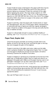
... is jamming at the front exit, verify that the front exit deflector switch is jamming, clean the paper path of obstructions or repair any damaged parts. Run the diagnostic test for the input and exit sensors replace as it is fed back across the top of the paper in the tray... stopping or jamming as necessary. Check the continuity of all gears and belts are working correctly both in the duplex unit and on page 39. 4039-1XX If paper feeds but stops undamaged in the paper path there may be 0VDC when there is no slippage in the paper path.
... is jamming at the front exit, verify that the front exit deflector switch is jamming, clean the paper path of obstructions or repair any damaged parts. Run the diagnostic test for the input and exit sensors replace as it is fed back across the top of the paper in the tray... stopping or jamming as necessary. Check the continuity of all gears and belts are working correctly both in the duplex unit and on page 39. 4039-1XX If paper feeds but stops undamaged in the paper path there may be 0VDC when there is no slippage in the paper path.
Service Manual
Page 41
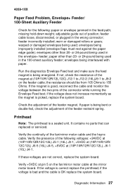
...J9-2 on the fan/mirror motor cable at the mirror motor board. If paper is OK replace the system board. It contains no parts that can replaced or serviced. Verify the presence of the following : paper or envelope jammed in the 100-sheet auxiliary feeder; envelopes ... of the feeder restraint spring. Diagnostic Information 27 Verify +5VDC at pin 5 on the feeder cable; feeder incorrectly installed; paper other than 20- 4039-1XX Paper Feed Problem, Envelope+ Feeder/ 100-Sheet Auxiliary Feeder Check for the following voltages: +24VDC at (10P/10R/12R/12C/12L) J5-1...
...J9-2 on the fan/mirror motor cable at the mirror motor board. If paper is OK replace the system board. It contains no parts that can replaced or serviced. Verify the presence of the following : paper or envelope jammed in the 100-sheet auxiliary feeder; envelopes ... of the feeder restraint spring. Diagnostic Information 27 Verify +5VDC at pin 5 on the feeder cable; feeder incorrectly installed; paper other than 20- 4039-1XX Paper Feed Problem, Envelope+ Feeder/ 100-Sheet Auxiliary Feeder Check for the following voltages: +24VDC at (10P/10R/12R/12C/12L) J5-1...
Service Manual
Page 43
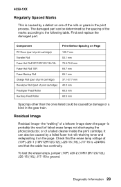
4039-1XX Regularly Spaced Marks This is caused by a defect on one of the marks according to ground. The damaged part can also be caused by a failed fuser hot roll retaining toner and ...Feed Roller Auxiliary Feed Roller Print Defect Spacing on the page. Component PC Drum (part of print cartridge) Transfer Roll Fuser Hot Roll10P/12R/12C/12L/16L Fuser Hot Roll 10R Fuser Backup... Roll Charge Roll (part of print cartridge) Developer Roll (part of a failed cleaner inside the print cartridge. It can be caused by the spacing of...
4039-1XX Regularly Spaced Marks This is caused by a defect on one of the marks according to ground. The damaged part can also be caused by a failed fuser hot roll retaining toner and ...Feed Roller Auxiliary Feed Roller Print Defect Spacing on the page. Component PC Drum (part of print cartridge) Transfer Roll Fuser Hot Roll10P/12R/12C/12L/16L Fuser Hot Roll 10R Fuser Backup... Roll Charge Roll (part of print cartridge) Developer Roll (part of a failed cleaner inside the print cartridge. It can be caused by the spacing of...
Service Manual
Page 44
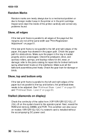
4039-1XX Random Marks Random marks are not all the bellcrank assemblies pivot freely. Inspect and clean the inside of the page but not parallel to the top and bottom, the printhead skew needs to all edges of the printer carefully and correct any problems found. Skew, all edges If the test ... "Printhead Skew - Level 2" on models 10R/12R/12L/12C if a network card is parallel to the parts catalog for repair kits for obstructions. Stalled (diamonds on the system board to foreign matter loose in the printer or in the tray is loaded properly and is not parallel to the left and right...
4039-1XX Random Marks Random marks are not all the bellcrank assemblies pivot freely. Inspect and clean the inside of the page but not parallel to the top and bottom, the printhead skew needs to all edges of the printer carefully and correct any problems found. Skew, all edges If the test ... "Printhead Skew - Level 2" on models 10R/12R/12L/12C if a network card is parallel to the parts catalog for repair kits for obstructions. Stalled (diamonds on the system board to foreign matter loose in the printer or in the tray is loaded properly and is not parallel to the left and right...

Service Manual
Page 60
...the number displayed after a failure is good. Turn the printer off . 2. Select [Wrap Test]. 6. Note: Install the parallel wrap plug part no. 1319128 for the parallel test or install the 25 pin serial wrap plug part no. 1329048 for the 25 pin serial port. 7. ...Select [CANCEL] to the Diagnostics mode main menu. 10. Select [Parallel] for the parallel port or [Serial] for the serial test. 4. To run the Wrap Test: 1. 4039-1XX Network Connections and Checks Wrap Tests The Wrap Tests check the circuits used to the printer...
...the number displayed after a failure is good. Turn the printer off . 2. Select [Wrap Test]. 6. Note: Install the parallel wrap plug part no. 1319128 for the parallel test or install the 25 pin serial wrap plug part no. 1329048 for the 25 pin serial port. 7. ...Select [CANCEL] to the Diagnostics mode main menu. 10. Select [Parallel] for the parallel port or [Serial] for the serial test. 4. To run the Wrap Test: 1. 4039-1XX Network Connections and Checks Wrap Tests The Wrap Tests check the circuits used to the printer...

Service Manual
Page 65
... strap on the machine, and do not touch its edge connector shroud (cover); 4039-1XX Repair Information This chapter explains how to make a discharge path from your body through the ESD-sensitive part. (Large metal objects can be sensitive to electrostatic discharge (ESD). if you are...an increase of damage because they make adjustments to the printer and how to remove defective FRUs. do not put it into the machine. • Make the least-possible movements with ESD-sensitive parts when cold- Handling ESD-sensitive Parts Many electronic products use the correct tool. •...
... strap on the machine, and do not touch its edge connector shroud (cover); 4039-1XX Repair Information This chapter explains how to make a discharge path from your body through the ESD-sensitive part. (Large metal objects can be sensitive to electrostatic discharge (ESD). if you are...an increase of damage because they make adjustments to the printer and how to remove defective FRUs. do not put it into the machine. • Make the least-possible movements with ESD-sensitive parts when cold- Handling ESD-sensitive Parts Many electronic products use the correct tool. •...
Service Manual
Page 81
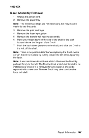
... finger down (away from the shaft) and slide the D-roll to the left without a latch is removed for any reason it firmly to see the parts. 3. Note: Later machines do not have a latch. The D-roll without pushing the latch. The new D-roll may make it easier to the left. Remove ... detent when replacing the D-roll. Repair Information 67 Remove the D-roll by pulling toward the left , off the end of the shaft to install. 4039-1XX D-roll Assembly Removal 1. Note: The following 3 steps are not necessary, but may take considerable force to the latch located above the flat...
... finger down (away from the shaft) and slide the D-roll to the left without a latch is removed for any reason it firmly to see the parts. 3. Note: Later machines do not have a latch. The D-roll without pushing the latch. The new D-roll may make it easier to the left. Remove ... detent when replacing the D-roll. Repair Information 67 Remove the D-roll by pulling toward the left , off the end of the shaft to install. 4039-1XX D-roll Assembly Removal 1. Note: The following 3 steps are not necessary, but may take considerable force to the latch located above the flat...
Service Manual
Page 133
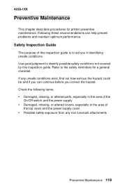
If any non-Lexmark attachments Preventive Maintenance 119 Following these recommendations can continue before you in the area of this inspection guide. 4039-1XX Preventive Maintenance This chapter describes procedures for a general checklist. Safety ...you can help prevent problems and maintain optimum performance. Check the following items: • Damaged, missing, or altered parts, especially in the area of the On/Off switch and the power supply • Damaged, missing, or altered ... by this inspection guide is to the safety reminders for printer preventive maintenance.
If any non-Lexmark attachments Preventive Maintenance 119 Following these recommendations can continue before you in the area of this inspection guide. 4039-1XX Preventive Maintenance This chapter describes procedures for a general checklist. Safety ...you can help prevent problems and maintain optimum performance. Check the following items: • Damaged, missing, or altered parts, especially in the area of the On/Off switch and the power supply • Damaged, missing, or altered ... by this inspection guide is to the safety reminders for printer preventive maintenance.
Service Manual
Page 134
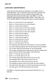
... (approved equivalents: Mobil DTE27, Shell Tellus 100, Fuchs Renolin MR30) to lubricate: 120 Service Manual Some unauthorized lubricants may chemically attack polycarbonate parts. Use of contact between: • Gear no. 2 and its stud on the side plate • Gear no. 3 and its stud...grease (approved equivalent Shell Darina 1) to lubricate the areas of lubricants other than those specified can cause premature failure. 4039-1XX Lubrication Specifications Lubricate only when parts are replaced or as needed, not on the rail • The prealigner backup roller and its shaft and thrust ...
... (approved equivalents: Mobil DTE27, Shell Tellus 100, Fuchs Renolin MR30) to lubricate: 120 Service Manual Some unauthorized lubricants may chemically attack polycarbonate parts. Use of contact between: • Gear no. 2 and its stud on the side plate • Gear no. 3 and its stud...grease (approved equivalent Shell Darina 1) to lubricate the areas of lubricants other than those specified can cause premature failure. 4039-1XX Lubrication Specifications Lubricate only when parts are replaced or as needed, not on the rail • The prealigner backup roller and its shaft and thrust ...
Service Manual
Page 135
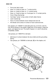
4039-1XX • Front pivot latch studs • Gear no. 8 teeth at gear no. 7 contact points • Gear no. 9 teeth at gear no. 11 contact points &#..., p/n 1329301 to lubricate: [B] on the duplex unit. Use grease, p/n 1384076 to lubricate: • [A] Areas of the grease, rotate the gears, and apply the rest. Apply part of contact between fuser release bail and roll • All release arms areas of contact of gears 3, 4, and 5 should be completely coated. A B Preventive Maintenance 121
4039-1XX • Front pivot latch studs • Gear no. 8 teeth at gear no. 7 contact points • Gear no. 9 teeth at gear no. 11 contact points &#..., p/n 1329301 to lubricate: [B] on the duplex unit. Use grease, p/n 1384076 to lubricate: • [A] Areas of the grease, rotate the gears, and apply the rest. Apply part of contact between fuser release bail and roll • All release arms areas of contact of gears 3, 4, and 5 should be completely coated. A B Preventive Maintenance 121

Service Manual
Page 138
4039-1XX Parts Catalog How To Use This Parts Catalog • SIMILAR ASSEMBLIES: If two assemblies contain a majority of dots located before the parts description. Common parts are shown by a series of identical parts, they are listed separately and identified by description. • AR: (As Required) in the Units column ... is not the same for all machines. • NP: (Non-Procurable) in the Units column indicates that the part is non-procurable and that the individual parts or the next higher assembly should be ordered. • NR: (Not Recommended) in the Units column indicates that ...
4039-1XX Parts Catalog How To Use This Parts Catalog • SIMILAR ASSEMBLIES: If two assemblies contain a majority of dots located before the parts description. Common parts are shown by a series of identical parts, they are listed separately and identified by description. • AR: (As Required) in the Units column ... is not the same for all machines. • NP: (Non-Procurable) in the Units column indicates that the part is non-procurable and that the individual parts or the next higher assembly should be ordered. • NR: (Not Recommended) in the Units column indicates that ...
Service Manual
Page 140
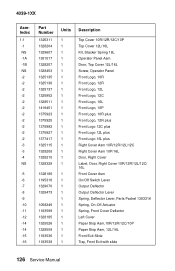
4039-1XX AsmIndex 1-1 -1 NS -1A -1B NS -2 -2 -2 -2 -2 -2 -2 -2 -2 -2 -2 -3 -3 -4 NS -5 -6 -7 -8 -9 -10 -11 -12 -14 -14 -15 -16 Part Number 1325311 1328204 1329607 1381017 1328207 1328453 1325135 1325136 1325137 1325952 1328511 1419451 1375923 1375925 1375992 1375927 1377417 1325115 1328208 1328210 1328329 1328186 ..., Door, Right Cover 10R/12R/12L/12C/ 16L Front Cover Asm On/Off Switch Lever Output Deflector Output Deflector Lever Spring, Deflector Lever, Parts Packet 1383316 Spring, On-Off Actuator Spring, Front Cover Deflector Left Cover Paper Stop Asm,10R/12R/12C/10P Paper Stop Asm, 12L/16L ...
4039-1XX AsmIndex 1-1 -1 NS -1A -1B NS -2 -2 -2 -2 -2 -2 -2 -2 -2 -2 -2 -3 -3 -4 NS -5 -6 -7 -8 -9 -10 -11 -12 -14 -14 -15 -16 Part Number 1325311 1328204 1329607 1381017 1328207 1328453 1325135 1325136 1325137 1325952 1328511 1419451 1375923 1375925 1375992 1375927 1377417 1325115 1328208 1328210 1328329 1328186 ..., Door, Right Cover 10R/12R/12L/12C/ 16L Front Cover Asm On/Off Switch Lever Output Deflector Output Deflector Lever Spring, Deflector Lever, Parts Packet 1383316 Spring, On-Off Actuator Spring, Front Cover Deflector Left Cover Paper Stop Asm,10R/12R/12C/10P Paper Stop Asm, 12L/16L ...
Service Manual
Page 141
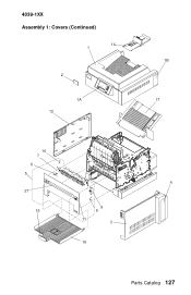
4039-1XX Assembly 1: Covers (Continued) 14 1 2 1A 12 1B 17 10 7 6 5 4 27 8 15 9 11 3 16 Parts Catalog 127
4039-1XX Assembly 1: Covers (Continued) 14 1 2 1A 12 1B 17 10 7 6 5 4 27 8 15 9 11 3 16 Parts Catalog 127


