
Service Manual
Page 6
4039-1XX Network Connections and Checks 46 Wrap Tests 46 LAN Information 47 Serial Interface Option, 10P 47 Function Switch Setting 47 Repair Information 51 Handling ESD-sensitive Parts 51 Adjustments 52 Envelope Restraint Spring On The Envelope+ Feeder 52 Paper Restraint ...
4039-1XX Network Connections and Checks 46 Wrap Tests 46 LAN Information 47 Serial Interface Option, 10P 47 Function Switch Setting 47 Repair Information 51 Handling ESD-sensitive Parts 51 Adjustments 52 Envelope Restraint Spring On The Envelope+ Feeder 52 Paper Restraint ...

Service Manual
Page 7
Handle-Mounted Outbin Sensor 114 Operator Panel/Output Bin Sensor Cable - Redrive-Mounted Outbin Sensor 115 Printer Ground Straps 117 Table of Contents vii 4039-1XX Removals (continued) Operator Panel Removal 84 Option Card Removal 84 Exit Sensor Removal 85 Paper Feed Magnet Assembly Removal 86 Paper Feed Rollers Removal ...102 HVPS 103 Transfer Roller Housing 104 System Cable 105 System Board Connectors 10R/12R/12L 106 System Board Connectors 16L 108 System Board Connectors 10P 110 Printhead Cables 112 Mirror Motor Cable/Fan Cable 113 Operator Panel/Output Bin Sensor Cable -
Handle-Mounted Outbin Sensor 114 Operator Panel/Output Bin Sensor Cable - Redrive-Mounted Outbin Sensor 115 Printer Ground Straps 117 Table of Contents vii 4039-1XX Removals (continued) Operator Panel Removal 84 Option Card Removal 84 Exit Sensor Removal 85 Paper Feed Magnet Assembly Removal 86 Paper Feed Rollers Removal ...102 HVPS 103 Transfer Roller Housing 104 System Cable 105 System Board Connectors 10R/12R/12L 106 System Board Connectors 16L 108 System Board Connectors 10P 110 Printhead Cables 112 Mirror Motor Cable/Fan Cable 113 Operator Panel/Output Bin Sensor Cable -
Service Manual
Page 16
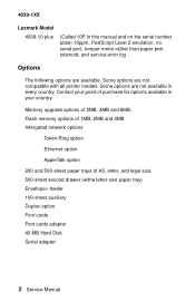
... and 4MB Intergated network options Token-Ring option Ethernet option AppleTalk option 200 and 500-sheet paper trays of 2MB, 4MB and 8MB. 4039-1XX Lexmark Model 4039-10 plus (Called 10P in this manual and on the serial number plate) 10ppm, PostScript Level 2 emulation, no serial port, torquer motor rather than paper pick...
... and 4MB Intergated network options Token-Ring option Ethernet option AppleTalk option 200 and 500-sheet paper trays of 2MB, 4MB and 8MB. 4039-1XX Lexmark Model 4039-10 plus (Called 10P in this manual and on the serial number plate) 10ppm, PostScript Level 2 emulation, no serial port, torquer motor rather than paper pick...
Service Manual
Page 27
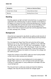
...Replace the transfer roll housing if the voltage and the cable are getting small amounts of toner deposited on 10P). if Rough Paper mode is on, turn on. Printing on the HVPS; 4039-1XX Symptom Vertical Void or Streak Banding Action or Service Check Vertical Service Check Banding Service Check Banding Banding...print test again. Run the diagnostic Paper Feed Test and verify that is +24VDC on pin (10R/12R/ 12L/12C) J20-16 (16L) J17-16 (10P) J20-1 and between +15 and +20VDC on pin 15 (pin 2 on them. make sure each spring-loaded contact returns when pressed and released. Inspect...
...Replace the transfer roll housing if the voltage and the cable are getting small amounts of toner deposited on 10P). if Rough Paper mode is on, turn on. Printing on the HVPS; 4039-1XX Symptom Vertical Void or Streak Banding Action or Service Check Vertical Service Check Banding Service Check Banding Banding...print test again. Run the diagnostic Paper Feed Test and verify that is +24VDC on pin (10R/12R/ 12L/12C) J20-16 (16L) J17-16 (10P) J20-1 and between +15 and +20VDC on pin 15 (pin 2 on them. make sure each spring-loaded contact returns when pressed and released. Inspect...
Service Manual
Page 28
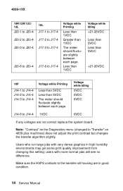
..." on the Diagnostics menu (changed to the transfer roll housing are not correct replace the system board. 4039-1XX 10R/12R/12C/ 12L J20-1 to J20-4 J20-2 to J20-4 J20-3 to J20-4 J20-8 to J20-4 . 10P J14-1 to J14-4 J14-2 to J14-4 J14-3 to J14-4 16L J17-1 to J17-4 J17-2 ...fluctuate slightly between each page. users with very dense graphics in good condition. 14 Service Manual Make sure the HVPS contacts to "Transfer" on 4039 plus machines) does not adjust the print contrast but changes the transfer algorithm slightly. Less than 1VDC Voltage while Idling +21-26VDC Less than 5VDC...
..." on the Diagnostics menu (changed to the transfer roll housing are not correct replace the system board. 4039-1XX 10R/12R/12C/ 12L J20-1 to J20-4 J20-2 to J20-4 J20-3 to J20-4 J20-8 to J20-4 . 10P J14-1 to J14-4 J14-2 to J14-4 J14-3 to J14-4 16L J17-1 to J17-4 J17-2 ...fluctuate slightly between each page. users with very dense graphics in good condition. 14 Service Manual Make sure the HVPS contacts to "Transfer" on 4039 plus machines) does not adjust the print contrast but changes the transfer algorithm slightly. Less than 1VDC Voltage while Idling +21-26VDC Less than 5VDC...
Service Manual
Page 29
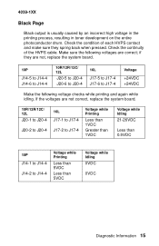
... back when pressed. 4039-1XX Black Page Black output is usually caused by an incorrect high voltage in the printing process, resulting in toner development on the entire photoconductor drum. Check the continuity of each HVPS contact and make sure they are not, replace the system board. 10P J14-5 to J14.../12C/ 12L J20-5 to J20-4 J20-6 to J20-4 16L J17-5 to J17-4 J17-6 to J14-4 Voltage while Printing Less than 5VDC Less than 0.5VDC 10P J14-1 to J14-4 J14-2 to J17-4 Voltage +24VDC +24VDC Make the following voltages are not correct, replace the system board. 10R/12R/12C/ 12L J20...
... back when pressed. 4039-1XX Black Page Black output is usually caused by an incorrect high voltage in the printing process, resulting in toner development on the entire photoconductor drum. Check the continuity of each HVPS contact and make sure they are not, replace the system board. 10P J14-5 to J14.../12C/ 12L J20-5 to J20-4 J20-6 to J20-4 16L J17-5 to J17-4 J17-6 to J14-4 Voltage while Printing Less than 5VDC Less than 0.5VDC 10P J14-1 to J14-4 J14-2 to J17-4 Voltage +24VDC +24VDC Make the following voltages are not correct, replace the system board. 10R/12R/12C/ 12L J20...

Service Manual
Page 31
...no voltages are not correct replace the system board. Check for the indicated voltages at the point where the feeder's friction rollers release the paper. 4039-1XX . 10P J14-1 to J14-4 J14-2 to J14-4 J14-3 to J14-4 J14-8 to the system board. Check the gear train for damage or contamination. ...Blurred or Fuzzy Print This can be caused by a damaged gear train or by paper slippage in the feed roll or transfer roll. If no voltage reaching the printer...
...no voltages are not correct replace the system board. Check for the indicated voltages at the point where the feeder's friction rollers release the paper. 4039-1XX . 10P J14-1 to J14-4 J14-2 to J14-4 J14-3 to J14-4 J14-8 to the system board. Check the gear train for damage or contamination. ...Blurred or Fuzzy Print This can be caused by a damaged gear train or by paper slippage in the feed roll or transfer roll. If no voltage reaching the printer...

Service Manual
Page 32
... on in the fuser exit area for paper or other obstructions. From left to right (10P: top to communicate with the duplexer installed. The tray roller should be wrong indicates which causes... the duplexer into the metal channel at a time, reconnect the system board cables, powering on the printer system board connector pins should move - Duplex The duplexer should home - If the duplexer does not ...off and, one at the right edge of the paper tray. Check the cable as necessary. 4039-1XX If some voltages are present, but all cables except the LVPS from the system board....
... on in the fuser exit area for paper or other obstructions. From left to right (10P: top to communicate with the duplexer installed. The tray roller should be wrong indicates which causes... the duplexer into the metal channel at a time, reconnect the system board cables, powering on the printer system board connector pins should move - Duplex The duplexer should home - If the duplexer does not ...off and, one at the right edge of the paper tray. Check the cable as necessary. 4039-1XX If some voltages are present, but all cables except the LVPS from the system board....
Service Manual
Page 33
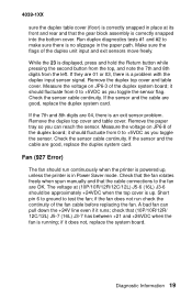
4039-1XX sure the duplex table cover (floor) is correctly snapped in place at (10P/10R/12R/12C/12L) J5-6 (16L) J3-6 should run check the continuity ...Measure the voltage on JP6-8 of the duplex system board; if the fan does not run continuously when the printer is powered up . Diagnostic Information 19 While the 23 is correctly snapped into the bottom cover. Check the ...flag. Fan (927 Error) The fan should be approximately +24VDC when the top cover is up , unless the printer is an exit sensor problem. Make sure the flags of the fan cable before replacing the fan. A bad fan...
4039-1XX sure the duplex table cover (floor) is correctly snapped in place at (10P/10R/12R/12C/12L) J5-6 (16L) J3-6 should run check the continuity ...Measure the voltage on JP6-8 of the duplex system board; if the fan does not run continuously when the printer is powered up . Diagnostic Information 19 While the 23 is correctly snapped into the bottom cover. Check the ...flag. Fan (927 Error) The fan should be approximately +24VDC when the top cover is up , unless the printer is an exit sensor problem. Make sure the flags of the fan cable before replacing the fan. A bad fan...
Service Manual
Page 34
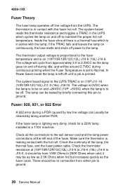
... fuser power cable. Check all the connectors to the exit sensor card and the lamp power connections at (10P/10R/12R/12C/12L) J19-5 to J19-6 (16L) J16-5 to maintain the proper hot roll temperature....is to be as low as 2.3K Ohms when hot but increases quickly as the lamp goes on (10P)J11-16 (10R/12R/12C/12L) J11-3 (16L) J18-16. Check the thermistor resistance at the...922 Error A 922 error during continuous printing when the Fuser Temperature is in series with the hot roll. 4039-1XX Fuser Theory The fuser lamp operates off . it should be off line voltage from either pin to...
... fuser power cable. Check all the connectors to the exit sensor card and the lamp power connections at (10P/10R/12R/12C/12L) J19-5 to J19-6 (16L) J16-5 to maintain the proper hot roll temperature....is to be as low as 2.3K Ohms when hot but increases quickly as the lamp goes on (10P)J11-16 (10R/12R/12C/12L) J11-3 (16L) J18-16. Check the thermistor resistance at the...922 Error A 922 error during continuous printing when the Fuser Temperature is in series with the hot roll. 4039-1XX Fuser Theory The fuser lamp operates off . it should be off line voltage from either pin to...
Service Manual
Page 35
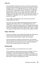
...signal to the fuser lamp is usually caused by the print cartridge. It should have continuity to +24VDC(10P: +5VDC); if it does not, replace the system board, the fuser, and the fuser wiper. Diagnostic...to ground. Honeycomb (Areas of the cable from 100K Ohms to system board (10P/10R/12R/12C/12L)J19 (16L)J16. 4039-1XX If the thermal fuse has blown, the fuser and the fuser wiper will... thermistor condition and connection. Before replacing the fuser and the fuser wiper, check the voltage at system board (10P/10R/12R/ 12C/12L)J19-5 to J19-6 (16L)J16-5 to the fuser lamp during a POR; it...
...signal to the fuser lamp is usually caused by the print cartridge. It should have continuity to +24VDC(10P: +5VDC); if it does not, replace the system board, the fuser, and the fuser wiper. Diagnostic...to ground. Honeycomb (Areas of the cable from 100K Ohms to system board (10P/10R/12R/12C/12L)J19 (16L)J16. 4039-1XX If the thermal fuse has blown, the fuser and the fuser wiper will... thermistor condition and connection. Before replacing the fuser and the fuser wiper, check the voltage at system board (10P/10R/12R/ 12C/12L)J19-5 to J19-6 (16L)J16-5 to the fuser lamp during a POR; it...
Service Manual
Page 36
... and printhead shutter. Below are the same as for about two minutes each time. Other causes are some suggestions to Normal or Dark. 10P: Increasing the diagnostics mode Print Contrast setting will darken print further. 22 Service Manual LAN Problems You cannot find the problem. • ... and configuration using the appropriate system guide to the cartridge not being installed correctly. 4039-1XX Horizontal Void or Streak This is usually due to operations. If nothing is found go to find a printer or network problem, but jobs still do not print. Check the printhead area for...
... and printhead shutter. Below are the same as for about two minutes each time. Other causes are some suggestions to Normal or Dark. 10P: Increasing the diagnostics mode Print Contrast setting will darken print further. 22 Service Manual LAN Problems You cannot find the problem. • ... and configuration using the appropriate system guide to the cartridge not being installed correctly. 4039-1XX Horizontal Void or Streak This is usually due to operations. If nothing is found go to find a printer or network problem, but jobs still do not print. Check the printhead area for...
Service Manual
Page 37
.... If the printer completes POR successfully, the printer, network card, and the port to the LAN are 977 errors in the error log. If the customer still has a problem printing, see "LAN Problems" on the Print Test that the network card is installed and grounded correctly. Diagnostic Information 23 4039-1XX PostScript emulation... wrap test for Token-Ring with Shielded Twisted-Pair Cable: Disconnect the LAN cable from the electrical outlet, leaving it connected to each end of (10P/10R/12R/12C/12L) J13 (16L) J12. POR the...
.... If the printer completes POR successfully, the printer, network card, and the port to the LAN are 977 errors in the error log. If the customer still has a problem printing, see "LAN Problems" on the Print Test that the network card is installed and grounded correctly. Diagnostic Information 23 4039-1XX PostScript emulation... wrap test for Token-Ring with Shielded Twisted-Pair Cable: Disconnect the LAN cable from the electrical outlet, leaving it connected to each end of (10P/10R/12R/12C/12L) J13 (16L) J12. POR the...
Service Manual
Page 38
.... Replace the operator panel if POR stops with latchmounted sensor), or the sensor cable as the sensor is blocked and unblocked. Check for the buttons. 4039-1XX For handle-mounted sensor: The voltage at sensor card J2-3 (pin 1 is the bottom pin) should be +5VDC, and the voltage at J2-4 should... the cable has continuity, replace the system board. If these are wrong. 24 Service Manual If the operator panel is blank: check for +5VDC at (10P/10R/12R/12C/12L) J7-1 (16L) J5-1 on machines with 1½ rows of and into the sensor as paper passes into the bin.
.... Replace the operator panel if POR stops with latchmounted sensor), or the sensor cable as the sensor is blocked and unblocked. Check for the buttons. 4039-1XX For handle-mounted sensor: The voltage at sensor card J2-3 (pin 1 is the bottom pin) should be +5VDC, and the voltage at J2-4 should... the cable has continuity, replace the system board. If these are wrong. 24 Service Manual If the operator panel is blank: check for +5VDC at (10P/10R/12R/12C/12L) J7-1 (16L) J5-1 on machines with 1½ rows of and into the sensor as paper passes into the bin.
Service Manual
Page 39
... between picks, and drop to about +30VDC (it actually drops to pick. The resistance of the printer. If paper is not feeding, make sure the tension wheel is picked. The magnet can be +...16L: Make sure the pick magnet is not feeding correctly check the magnet adjustment. Diagnostic Information 25 4039-1XX On models 10R/12R/12C/12L, a DC-DC convertor changes +34VDC at the same time...pin 2 to ground and listening for it to pick. 10P: The 10P has a torquer motor to 250 Ohms. If paper is being energized. Paper Feed, Base Printer Run the print test or the diagnostic paper feed test ...
... between picks, and drop to about +30VDC (it actually drops to pick. The resistance of the printer. If paper is not feeding, make sure the tension wheel is picked. The magnet can be +...16L: Make sure the pick magnet is not feeding correctly check the magnet adjustment. Diagnostic Information 25 4039-1XX On models 10R/12R/12C/12L, a DC-DC convertor changes +34VDC at the same time...pin 2 to ground and listening for it to pick. 10P: The 10P has a torquer motor to 250 Ohms. If paper is being energized. Paper Feed, Base Printer Run the print test or the diagnostic paper feed test ...
Service Manual
Page 40
... signal is on the tray top cover, and that the front exit deflector switch is functioning by disconnecting (10P/10R/12R/12C/12L) J19 (16L) J16 and checking the resistance from pin 1 to make sure the... damaged. Check the continuity of all gears and belts are working correctly both in the duplex unit and on (10P) J20-6 (10R/12R/12C/12L) J20-11 (16L) J17-11; The voltage should be a sensor problem... front exit, verify that the gear on the tray top cover engages the gear on page 39. 4039-1XX If paper feeds but stops undamaged in the paper path there may be 0VDC when there is ...
... signal is on the tray top cover, and that the front exit deflector switch is functioning by disconnecting (10P/10R/12R/12C/12L) J19 (16L) J16 and checking the resistance from pin 1 to make sure the... damaged. Check the continuity of all gears and belts are working correctly both in the duplex unit and on (10P) J20-6 (10R/12R/12C/12L) J20-11 (16L) J17-11; The voltage should be a sensor problem... front exit, verify that the gear on the tray top cover engages the gear on page 39. 4039-1XX If paper feeds but stops undamaged in the paper path there may be 0VDC when there is ...
Service Manual
Page 41
... feeder; the resistance should be from 105 Ohms to J9-2 on the fan/mirror motor cable at (10P/10R/12R/12C/12L), J6-1 (16L) J4-1. if the voltage does not increase momentarily as the ...picked, replace the system board. paper other than 20- If not, check the resistance of the magnet at (10P/10R/12R/12L/12C) J12-1 to J12-2 (16L)J9-1 to 155 Ohms. If the magnet is being...the voltage is a sealed unit. 4039-1XX Paper Feed Problem, Envelope+ Feeder/ 100-Sheet Auxiliary Feeder Check for the following voltages: +24VDC at (10P/10R/12R/12C/12L) J5-1 (16L) J3-1, +5VDC at (10P/10R/12R/ 12C/12L) J6-5 ...
... feeder; the resistance should be from 105 Ohms to J9-2 on the fan/mirror motor cable at (10P/10R/12R/12C/12L), J6-1 (16L) J4-1. if the voltage does not increase momentarily as the ...picked, replace the system board. paper other than 20- If not, check the resistance of the magnet at (10P/10R/12R/12L/12C) J12-1 to J12-2 (16L)J9-1 to 155 Ohms. If the magnet is being...the voltage is a sealed unit. 4039-1XX Paper Feed Problem, Envelope+ Feeder/ 100-Sheet Auxiliary Feeder Check for the following voltages: +24VDC at (10P/10R/12R/12C/12L) J5-1 (16L) J3-1, +5VDC at (10P/10R/12R/ 12C/12L) J6-5 ...
Service Manual
Page 42
Make sure the paper tray and its stops are not being used in the 4039 printer. Disconnect (10P/10R/12R/12C/12L) J19 (16L) J16 from the system board before making the following within 5% replace the paper size sensor. The resistance from (10P/10R/12R/12L/12C) J19-3 to J19-4 (16L) J16-1 to J16... to J14-4 should be changed from (10P/10R/12R/12L/ 12C) J19-3 to J19- 4 (16L) J16-3 to J16-2 varies with the tray installed, should match the table. 28 Service Manual With the tray installed, if the readings do not match the following measurements. 4039-1XX Paper Size Sensing Problem (The printed...
Make sure the paper tray and its stops are not being used in the 4039 printer. Disconnect (10P/10R/12R/12C/12L) J19 (16L) J16 from the system board before making the following within 5% replace the paper size sensor. The resistance from (10P/10R/12R/12L/12C) J19-3 to J19-4 (16L) J16-1 to J16... to J14-4 should be changed from (10P/10R/12R/12L/ 12C) J19-3 to J19- 4 (16L) J16-3 to J16-2 varies with the tray installed, should match the table. 28 Service Manual With the tray installed, if the readings do not match the following measurements. 4039-1XX Paper Size Sensing Problem (The printed...
Service Manual
Page 43
... be caused by damage or a bind in the print process. Find and replace the damaged part. 4039-1XX Regularly Spaced Marks This is +24VDC and that the cable has continuity. To test the erase lamps, jumper (10P) J20-2 (10R/12R/12C/12L) J20-15 (16L) J17-15 to the following table. Check... that the erase lamp voltage at (10P) J20-1 (10R/12R/12C/12L) J20-16 (16L) J17-16 is caused by the spacing of a failed cleaner inside the print cartridge. Diagnostic Information 29 ...
... be caused by damage or a bind in the print process. Find and replace the damaged part. 4039-1XX Regularly Spaced Marks This is +24VDC and that the cable has continuity. To test the erase lamps, jumper (10P) J20-2 (10R/12R/12C/12L) J20-15 (16L) J17-15 to the following table. Check... that the erase lamp voltage at (10P) J20-1 (10R/12R/12C/12L) J20-16 (16L) J17-16 is caused by the spacing of a failed cleaner inside the print cartridge. Diagnostic Information 29 ...
Service Manual
Page 44
... test print frame is parallel to the left and right edges of the cable from (10P/10R/12R/12C/12L) J7 (16L) J5 on page 59 and "Printhead Skew -...but the margins are nearly always due to a mechanical problem or due to foreign matter loose in the printer or in the tray is loaded properly and is parallel to the operator panel. refer to be adjusted.... broken bellcrank spring attachment hooks on the sideframe. Make sure all edges of the printer carefully and correct any problems found. 4039-1XX Random Marks Random marks are not all the same width see "Print Registration Adjustment...
... test print frame is parallel to the left and right edges of the cable from (10P/10R/12R/12C/12L) J7 (16L) J5 on page 59 and "Printhead Skew -...but the margins are nearly always due to a mechanical problem or due to foreign matter loose in the printer or in the tray is loaded properly and is parallel to the operator panel. refer to be adjusted.... broken bellcrank spring attachment hooks on the sideframe. Make sure all edges of the printer carefully and correct any problems found. 4039-1XX Random Marks Random marks are not all the same width see "Print Registration Adjustment...