

Service Manual
Page 7
Redrive-Mounted Outbin Sensor 115 Printer Ground Straps 117 Table of Contents vii Handle-Mounted Outbin Sensor 114 Operator Panel/Output Bin Sensor Cable - 4039-1XX Removals (continued) Operator Panel Removal 84 Option Card Removal 84 Exit Sensor Removal 85 Paper Feed Magnet Assembly Removal ...100 Connector Locations 101 Major Assembly Locations 101 Gear Train 102 HVPS 103 Transfer Roller Housing 104 System Cable 105 System Board Connectors 10R/12R/12L 106 System Board Connectors 16L 108 System Board Connectors 10P 110 Printhead Cables 112 Mirror Motor Cable/Fan Cable 113 ...
Redrive-Mounted Outbin Sensor 115 Printer Ground Straps 117 Table of Contents vii Handle-Mounted Outbin Sensor 114 Operator Panel/Output Bin Sensor Cable - 4039-1XX Removals (continued) Operator Panel Removal 84 Option Card Removal 84 Exit Sensor Removal 85 Paper Feed Magnet Assembly Removal ...100 Connector Locations 101 Major Assembly Locations 101 Gear Train 102 HVPS 103 Transfer Roller Housing 104 System Cable 105 System Board Connectors 10R/12R/12L 106 System Board Connectors 16L 108 System Board Connectors 10P 110 Printhead Cables 112 Mirror Motor Cable/Fan Cable 113 ...
Service Manual
Page 15
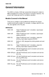
...For example, a voltage callout for printing labels and card stock 4039-16L 16ppm PostScript Level 1 emulation, output bin sensing, input/output capacity 500/500 4039-10R plus 10R with PostScript Level 2 emulation and service error log (RPQ only) 4039-12R plus 12R with PostScript Level 2 emulation and service error.../500 4039-12C Similar to most types of 600 dpi Laserprinters designed to attach to IBM-compatible PC's and to 12R, designed for the 16L also applies to the 16L plus models. The printer has PostScript and PCL emulation standard. 4039-1XX General Information The 4039 is ...
...For example, a voltage callout for printing labels and card stock 4039-16L 16ppm PostScript Level 1 emulation, output bin sensing, input/output capacity 500/500 4039-10R plus 10R with PostScript Level 2 emulation and service error log (RPQ only) 4039-12R plus 12R with PostScript Level 2 emulation and service error.../500 4039-12C Similar to most types of 600 dpi Laserprinters designed to attach to IBM-compatible PC's and to 12R, designed for the 16L also applies to the 16L plus models. The printer has PostScript and PCL emulation standard. 4039-1XX General Information The 4039 is ...
Service Manual
Page 27
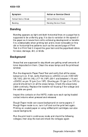
... paper or using refilled print cartridges can also cause background. Printing on some papers; It is undetectable when printing text and is +24VDC on pin (10R/12R/ 12L/12C) J20-16 (16L) J17-16 (10P) J20-1 and between +15 and +20VDC on pin 15 (pin 2 on 10P). Run the ... good. make sure each spring-loaded contact returns when pressed and released. then stop the test and check the voltages again: Diagnostic Information 13 4039-1XX Symptom Vertical Void or Streak Banding Action or Service Check Vertical Service Check Banding Service Check Banding Banding appears as it off and run...
... paper or using refilled print cartridges can also cause background. Printing on some papers; It is undetectable when printing text and is +24VDC on pin (10R/12R/ 12L/12C) J20-16 (16L) J17-16 (10P) J20-1 and between +15 and +20VDC on pin 15 (pin 2 on 10P). Run the ... good. make sure each spring-loaded contact returns when pressed and released. then stop the test and check the voltages again: Diagnostic Information 13 4039-1XX Symptom Vertical Void or Streak Banding Action or Service Check Vertical Service Check Banding Service Check Banding Banding appears as it off and run...
Service Manual
Page 28
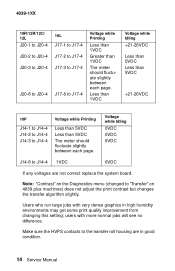
... dense graphics in good condition. 14 Service Manual Note: "Contrast" on the Diagnostics menu (changed to "Transfer" on 4039 plus machines) does not adjust the print contrast but changes the transfer algorithm slightly. 4039-1XX 10R/12R/12C/ 12L J20-1 to J20-4 J20-2 to J20-4 J20-3 to J20-4 J20-8 to J20-4 . 10P J14...
... dense graphics in good condition. 14 Service Manual Note: "Contrast" on the Diagnostics menu (changed to "Transfer" on 4039 plus machines) does not adjust the print contrast but changes the transfer algorithm slightly. 4039-1XX 10R/12R/12C/ 12L J20-1 to J20-4 J20-2 to J20-4 J20-3 to J20-4 J20-8 to J20-4 . 10P J14...
Service Manual
Page 29
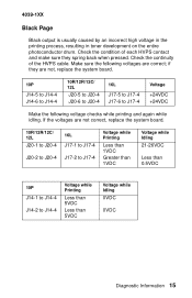
...J20-6 to J20-4 16L J17-5 to J17-4 J17-6 to J17-4 Voltage +24VDC +24VDC Make the following voltages are not correct, replace the system board. 10R/12R/12C/ 12L J20-1 to J20-4 J20-2 to J20-4 16L J17-1 to J17-4 J17-2 to J17-4 Voltage while Printing Less than 1VDC Greater than 1VDC...5VDC Less than 5VDC Voltage while Idling 0VDC 0VDC Diagnostic Information 15 If the voltages are correct; Check the condition of the HVPS cable. 4039-1XX Black Page Black output is usually caused by an incorrect high voltage in the printing process, resulting in toner development on the entire photoconductor...
...J20-6 to J20-4 16L J17-5 to J17-4 J17-6 to J17-4 Voltage +24VDC +24VDC Make the following voltages are not correct, replace the system board. 10R/12R/12C/ 12L J20-1 to J20-4 J20-2 to J20-4 16L J17-1 to J17-4 J17-2 to J17-4 Voltage while Printing Less than 1VDC Greater than 1VDC...5VDC Less than 5VDC Voltage while Idling 0VDC 0VDC Diagnostic Information 15 If the voltages are correct; Check the condition of the HVPS cable. 4039-1XX Black Page Black output is usually caused by an incorrect high voltage in the printing process, resulting in toner development on the entire photoconductor...
Service Manual
Page 30
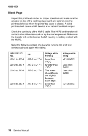
4039-1XX Blank Page Inspect the printhead shutter for proper operation and make sure the actuator on top of the HVPS cable. Check the continuity of the cartridge is present and extends into the printhead shroud when the printer top cover is making contact with the HVPS. Make sure the ...transfer roll contact under the left bearing is closed. Make the following voltage checks while running the print test continuously and again while idling. 10R/12R/12C/ 12L J20-1 to J20-4...
4039-1XX Blank Page Inspect the printhead shutter for proper operation and make sure the actuator on top of the HVPS cable. Check the continuity of the cartridge is present and extends into the printhead shroud when the printer top cover is making contact with the HVPS. Make sure the ...transfer roll contact under the left bearing is closed. Make the following voltage checks while running the print test continuously and again while idling. 10R/12R/12C/ 12L J20-1 to J20-4...
Service Manual
Page 33
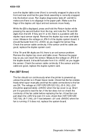
...the bottom cover. it should be approximately +24VDC when the top cover is up , unless the printer is in place at (10P/10R/12R/12C/12L) J5-6 (16L) J3-6 should fluctuate from 0 to +5VDC as you can ...replace the duplex system card. Check the sensor cable continuity. if the fan does not run continuously when the printer is powered up . If the sensor and the cable are 04, there is an exit sensor problem. Run...sensor cable continuity. Fan (927 Error) The fan should fluctuate from the left. 4039-1XX sure the duplex table cover (floor) is correctly snapped in Power Saver mode.
...the bottom cover. it should be approximately +24VDC when the top cover is up , unless the printer is in place at (10P/10R/12R/12C/12L) J5-6 (16L) J3-6 should fluctuate from 0 to +5VDC as you can ...replace the duplex system card. Check the sensor cable continuity. if the fan does not run continuously when the printer is powered up . If the sensor and the cable are 04, there is an exit sensor problem. Run...sensor cable continuity. Fan (927 Error) The fan should fluctuate from the left. 4039-1XX sure the duplex table cover (floor) is correctly snapped in Power Saver mode.
Service Manual
Page 34
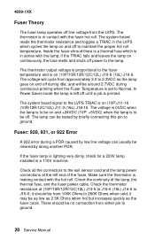
..., the thermal fuse, and the fuser power cable. 4039-1XX Fuser Theory The fuser lamp operates off line voltage from either pin to the LVPS TRIAC is on (10P/10R/12R/12C/12L) J19-6 (16L) J16-6. The ... the thermistor resistance at the left off . The voltage is 0VDC when the lamp is on (10P)J11-16 (10R/12R/12C/12L) J11-3 (16L) J18-16. it should be on continuously, the fuse melts and shuts off...connectors to be off until a job is to the exit sensor card and the lamp power connections at (10P/10R/12R/12C/12L) J19-5 to J19-6 (16L) J16-5 to the fuser temperature and is to be no ...
..., the thermal fuse, and the fuser power cable. 4039-1XX Fuser Theory The fuser lamp operates off line voltage from either pin to the LVPS TRIAC is on (10P/10R/12R/12C/12L) J19-6 (16L) J16-6. The ... the thermistor resistance at the left off . The voltage is 0VDC when the lamp is on (10P)J11-16 (10R/12R/12C/12L) J11-3 (16L) J18-16. it should be on continuously, the fuse melts and shuts off...connectors to be off until a job is to the exit sensor card and the lamp power connections at (10P/10R/12R/12C/12L) J19-5 to J19-6 (16L) J16-5 to the fuser temperature and is to be no ...
Service Manual
Page 35
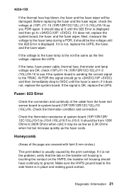
... not the same as the line voltage, replace the LVPS. Check the thermistor resistance at system board (10P/10R/12R/ 12C/12L)J19-5 to J19-6 (16L)J16-5 to ground. the transfer roll housing should have continuity...not, replace the system board, the fuser, and the fuser wiper. It should stay at (10P) J11-16 (10R/12R/12C/12L) J11-3 (16L)J18-16 as the fuser cools. Next, measure the voltage to 260K Ohms ...and making good contact. At POR this signal should be damaged. it is OK, replace the LVPS. 4039-1XX If the thermal fuse has blown, the fuser and the fuser wiper will be line voltage until...
... not the same as the line voltage, replace the LVPS. Check the thermistor resistance at system board (10P/10R/12R/ 12C/12L)J19-5 to J19-6 (16L)J16-5 to ground. the transfer roll housing should have continuity...not, replace the system board, the fuser, and the fuser wiper. It should stay at (10P) J11-16 (10R/12R/12C/12L) J11-3 (16L)J18-16 as the fuser cools. Next, measure the voltage to 260K Ohms ...and making good contact. At POR this signal should be damaged. it is OK, replace the LVPS. 4039-1XX If the thermal fuse has blown, the fuser and the fuser wiper will be line voltage until...
Service Manual
Page 37
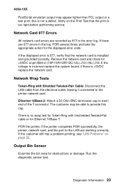
...bin area for the displayed error code. There is too light before performing service. Run the diagnostic sensor test. 4039-1XX PostScript emulation output may be able to the printer network card. If the customer still has a problem printing, see "LAN Problems" on the Print Test that the...connector. this cap. Network Card 977 Errors All network card errors are working correctly. If the printer completes POR successfully, the printer, network card, and the port to each end of (10P/10R/12R/12C/12L) J13 (16L) J12. Diagnostic Information 23 The customer may appear lighter than PCL...
...bin area for the displayed error code. There is too light before performing service. Run the diagnostic sensor test. 4039-1XX PostScript emulation output may be able to the printer network card. If the customer still has a problem printing, see "LAN Problems" on the Print Test that the...connector. this cap. Network Card 977 Errors All network card errors are working correctly. If the printer completes POR successfully, the printer, network card, and the port to each end of (10P/10R/12R/12C/12L) J13 (16L) J12. Diagnostic Information 23 The customer may appear lighter than PCL...
Service Manual
Page 38
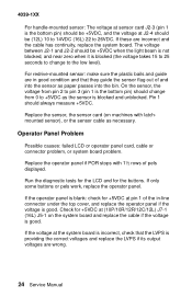
... panel if the voltage is good. Replace the sensor, the sensor card (on the system board and replace the cable if the voltage is good. 4039-1XX For handle-mounted sensor: The voltage at sensor card J2-3 (pin 1 is blocked (the voltage takes 15 to 25 seconds to change from pin... voltages and replace the LVPS if its output voltages are wrong. 24 Service Manual If the operator panel is blank: check for +5VDC at (10P/10R/12R/12C/12L) J7-1 (16L) J5-1 on machines with 1½ rows of the in good condition and that the LVPS is blocked and unblocked. Check...
... panel if the voltage is good. Replace the sensor, the sensor card (on the system board and replace the cable if the voltage is good. 4039-1XX For handle-mounted sensor: The voltage at sensor card J2-3 (pin 1 is blocked (the voltage takes 15 to 25 seconds to change from pin... voltages and replace the LVPS if its output voltages are wrong. 24 Service Manual If the operator panel is blank: check for +5VDC at (10P/10R/12R/12C/12L) J7-1 (16L) J5-1 on machines with 1½ rows of the in good condition and that the LVPS is blocked and unblocked. Check...
Service Manual
Page 39
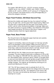
4039-1XX On models 10R/12R/12C/12L, a DC-DC convertor changes +34VDC at J11-4. Paper Feed, Base Printer Run the print test or the diagnostic paper feed test and carefully examine the area of the motor is the same as the 10R...voltage check is 88 Ohms. The motor can be +34V between the D-roll and the paper stack. 10R/12R/12C/12L/16L: Make sure the pick magnet is not damaged or stuck together. Diagnostic Information 25...It is meshing with the drive gear at the bottom of 100 to 250 Ohms. The voltage at (10R/12R/12C/12L) J22-2 (16L) J19-2 should be tested by shorting pin 2 to 250 Ohms....
4039-1XX On models 10R/12R/12C/12L, a DC-DC convertor changes +34VDC at J11-4. Paper Feed, Base Printer Run the print test or the diagnostic paper feed test and carefully examine the area of the motor is the same as the 10R...voltage check is 88 Ohms. The motor can be +34V between the D-roll and the paper stack. 10R/12R/12C/12L/16L: Make sure the pick magnet is not damaged or stuck together. Diagnostic Information 25...It is meshing with the drive gear at the bottom of 100 to 250 Ohms. The voltage at (10R/12R/12C/12L) J22-2 (16L) J19-2 should be tested by shorting pin 2 to 250 Ohms....
Service Manual
Page 40
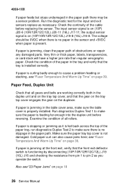
... Temperature And Warm-Up Time" on page 39. Examine the condition of the cable before reversing. The input sensor signal is functioning by disconnecting (10P/10R/12R/12C/12L) J19 (16L) J16 and checking the resistance from pin 1 to cause a problem feeding or stacking, see "Fuser Temperature And Warm-Up Time... at the front exit, verify that the gear on the tray top cover engages the gear on (10P/10R/12R/12C/12L) J19-8 (16L) J16-8. If paper is stopping or jamming as necessary. 4039-1XX If paper feeds but stops undamaged in the paper path there may be 0VDC when there is...
... Temperature And Warm-Up Time" on page 39. Examine the condition of the cable before reversing. The input sensor signal is functioning by disconnecting (10P/10R/12R/12C/12L) J19 (16L) J16 and checking the resistance from pin 1 to cause a problem feeding or stacking, see "Fuser Temperature And Warm-Up Time... at the front exit, verify that the gear on the tray top cover engages the gear on (10P/10R/12R/12C/12L) J19-8 (16L) J16-8. If paper is stopping or jamming as necessary. 4039-1XX If paper feeds but stops undamaged in the paper path there may be 0VDC when there is...
Service Manual
Page 41
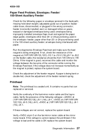
4039-1XX Paper Feed Problem, Envelope+ Feeder/ 100-Sheet Auxiliary Feeder Check for the following voltages: +24VDC at (10P/10R/12R/12C/12L) J5-1 (16L) J3-1, +5VDC at (10P/10R/12R/ 12C/12L) J6-5 (16L) J4-5, +5VDC at (10P/10R/12R/12C/12L), J6-1 (16L) J4-1. worn or damaged rollers or gears; or 24-pound... flaps must rest against the paper edge guide); the resistance should be from 105 Ohms to J9-2 on the fan/mirror motor cable at (10P/10R/12R/12L/12C) J12-1 to J12-2 (16L)J9-1 to 155 Ohms. If the magnet is being used in the envelope+ feeder; envelopes other than 20...
4039-1XX Paper Feed Problem, Envelope+ Feeder/ 100-Sheet Auxiliary Feeder Check for the following voltages: +24VDC at (10P/10R/12R/12C/12L) J5-1 (16L) J3-1, +5VDC at (10P/10R/12R/ 12C/12L) J6-5 (16L) J4-5, +5VDC at (10P/10R/12R/12C/12L), J6-1 (16L) J4-1. worn or damaged rollers or gears; or 24-pound... flaps must rest against the paper edge guide); the resistance should be from 105 Ohms to J9-2 on the fan/mirror motor cable at (10P/10R/12R/12L/12C) J12-1 to J12-2 (16L)J9-1 to 155 Ohms. If the magnet is being used in the envelope+ feeder; envelopes other than 20...
Service Manual
Page 42
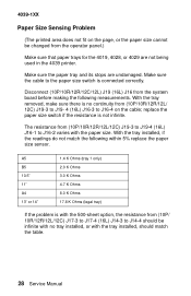
... K Ohms 4.7 K Ohms 8.0 K Ohms 17.8 K Ohms (legal tray) If the problem is no tray installed, or with the paper size. Disconnect (10P/10R/12R/12C/12L) J19 (16L) J16 from (10P/10R/12R/12L/ 12C) J19-3 to J19- 4 (16L) J16-3 to J16-4 on the page, or the paper size cannot be infinite with...making the following within 5% replace the paper size sensor. 4039-1XX Paper Size Sensing Problem (The printed area does not fit on the cable; Make sure the cable to J14-4 should match the table. 28 Service Manual Make sure the paper tray and its stops are not being used in the 4039 printer.
... K Ohms 4.7 K Ohms 8.0 K Ohms 17.8 K Ohms (legal tray) If the problem is no tray installed, or with the paper size. Disconnect (10P/10R/12R/12C/12L) J19 (16L) J16 from (10P/10R/12R/12L/ 12C) J19-3 to J19- 4 (16L) J16-3 to J16-4 on the page, or the paper size cannot be infinite with...making the following within 5% replace the paper size sensor. 4039-1XX Paper Size Sensing Problem (The printed area does not fit on the cable; Make sure the cable to J14-4 should match the table. 28 Service Manual Make sure the paper tray and its stops are not being used in the 4039 printer.
Service Manual
Page 43
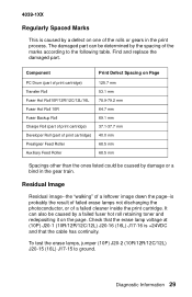
...gears in the gear train. Diagnostic Information 29 Check that the erase lamp voltage at (10P) J20-1 (10R/12R/12C/12L) J20-16 (16L) J17-16 is +24VDC and that the cable has continuity. To ...test the erase lamps, jumper (10P) J20-2 (10R/12R/12C/12L) J20-15 (16L) J17-15 to the following table. 4039-1XX Regularly Spaced Marks This is caused by a defect on the page. ...PC Drum (part of print cartridge) Transfer Roll Fuser Hot Roll10P/12R/12C/12L/16L Fuser Hot Roll 10R Fuser Backup Roll Charge Roll (part of print cartridge) Developer Roll (part of the marks according to...
...gears in the gear train. Diagnostic Information 29 Check that the erase lamp voltage at (10P) J20-1 (10R/12R/12C/12L) J20-16 (16L) J17-16 is +24VDC and that the cable has continuity. To ...test the erase lamps, jumper (10P) J20-2 (10R/12R/12C/12L) J20-15 (16L) J17-15 to the following table. 4039-1XX Regularly Spaced Marks This is caused by a defect on the page. ...PC Drum (part of print cartridge) Transfer Roll Fuser Hot Roll10P/12R/12C/12L/16L Fuser Hot Roll 10R Fuser Backup Roll Charge Roll (part of print cartridge) Developer Roll (part of the marks according to...
Service Manual
Page 44
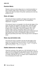
...all edges If the test print frame is not parallel to the left and right edges of the printer carefully and correct any problems found. Stalled (diamonds on display) Check the continuity of the paper, ...the printhead skew needs to the operator panel. Make sure the paper in the print cartridge. 4039-1XX Random Marks Random marks are not all the same width see "Print Registration Adjustment" on...the bellcrank assemblies pivot freely. Check the gear train for broken bellcrank spring attachment hooks on models 10R/12R/12L/12C if a network card is undamaged. Skew, top and bottom only If the ...
...all edges If the test print frame is not parallel to the left and right edges of the printer carefully and correct any problems found. Stalled (diamonds on display) Check the continuity of the paper, ...the printhead skew needs to the operator panel. Make sure the paper in the print cartridge. 4039-1XX Random Marks Random marks are not all the same width see "Print Registration Adjustment" on...the bellcrank assemblies pivot freely. Check the gear train for broken bellcrank spring attachment hooks on models 10R/12R/12L/12C if a network card is undamaged. Skew, top and bottom only If the ...
Service Manual
Page 119
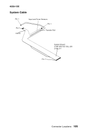
4039-1XX System Cable Pin 1 Pin 1 HVPS Input and Toner Sensors Pin 1 Transfer Roll System Board (10R/12R/12C/12L) J20 (16L) J17 Pin 1 Connector Locations 105
4039-1XX System Cable Pin 1 Pin 1 HVPS Input and Toner Sensors Pin 1 Transfer Roll System Board (10R/12R/12C/12L) J20 (16L) J17 Pin 1 Connector Locations 105
Service Manual
Page 121
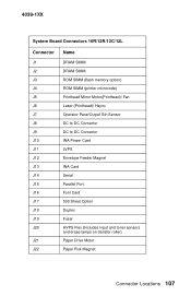
4039-1XX System Board Connectors 10R/12R/12C/12L Connector J1 J2 J3 J4 J5 J6 J7 J8 J9 J10 J11 J12 J13 J14 J15 J16 J17 J18 J19 J20 J21 J22 Name DRAM SIMM DRAM SIMM ROM SIMM (flash memory option) ROM SIMM (printer microcode) Printhead Mirror Motor(Printhead)/ Fan Laser (Printhead)/ Hsync Operator...
4039-1XX System Board Connectors 10R/12R/12C/12L Connector J1 J2 J3 J4 J5 J6 J7 J8 J9 J10 J11 J12 J13 J14 J15 J16 J17 J18 J19 J20 J21 J22 Name DRAM SIMM DRAM SIMM ROM SIMM (flash memory option) ROM SIMM (printer microcode) Printhead Mirror Motor(Printhead)/ Fan Laser (Printhead)/ Hsync Operator...
Service Manual
Page 126
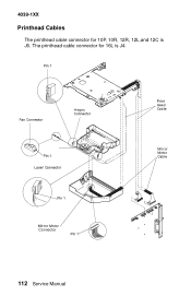
4039-1XX Printhead Cables The printhead cable connector for 16L is J6. The printhead cable connector for 10P, 10R, 12R, 12L,and 12C is J4. Connector 112 Service Manual
4039-1XX Printhead Cables The printhead cable connector for 16L is J6. The printhead cable connector for 10P, 10R, 12R, 12L,and 12C is J4. Connector 112 Service Manual